Development of a commercial electronic device from scratch
Greetings
I want to share my own experience in developing an electronic device. First, I will tell a little background, so that it is clear why this, in fact, was necessary for me.
Initially, we were developing software for chip tuning. One of the main tasks of which is to read the firmware from the computer (electronic engine control unit) and write it back. It is clear that for these purposes you need to somehow connect the computer and the ECU using an adapter. When earlier the overwhelming number of ECUs used the simplest method of receiving and transmitting data, it was enough to use the simplest adapter on transistors or a specialized chip. However, today most cars use the CAN bus to “communicate” their components with the external environment. The adapter for the CAN bus on transistors is no longer assembled, and here you definitely need a processor that will manage everything according to a specific program.
So the first problem arose - how to overcome CAN bus. In order not to reinvent the wheel, the choice is made on the use of a ready-made adapter that works according to the J2534 standard. For those who do not know, the J2534 standard is a standard that describes the hardware and software parts of the device with which you can connect to the computer through a computer. Developed by the Americans. The main reason for its development was the legislative consolidation of the possibility of updating the ECU firmware not by a specialized dealer service, but by anyone. Actually, if everyone can update the firmware on his phone, then why can not he do it with his car.
')
The most affordable import equivalent costs around $ 200. As it turned out later, two identical devices that meet the J2534 standard can work differently with the same software. Therefore, initially had to become attached to a specific manufacturer and its device.
Those functions that we needed in the "hardware", were present in the common adapter for diagnosing ELM327. It remains only to write the driver J2534 (in fact, it is a DLL, which serves as an interlayer between the program on the computer and the device itself). I previously contacted the ELM327 developers, but they said that they didn’t have plans to write such a driver, but they were ready to provide free firmware for ELM327. Previously, I had written such a driver that supported only the ISO 11898 (raw CAN) protocol. However, I was disappointed. With a CAN speed of 1Mb / s, ELM327 simply does not have time to receive such a large number of packets, constantly knocking out an error due to overflow of the internal message buffer. In addition, the exchange protocol between the computer and the ELM327 is organized in the form of ASCII messaging (so that it is convenient to work in the terminal). Accordingly, instead of transmitting one byte of data, three are transmitted (two bytes are the display of characters plus a separating space). It turned out that most of the USB traffic was wasted. And considering that the maximum speed of work with ELM327 via USB is 3 Mb / s, then with such an exchange organization, it is not possible to receive 1 Mb / s via CAN bus.
I never liked to depend on anyone, therefore, the idea to create my J2534 adapter did not leave me.
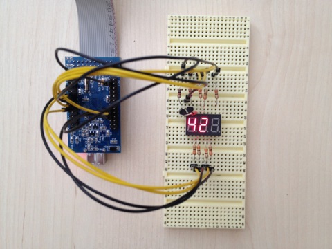
I should say here that before developing my J2534 adapter I didn’t have any development experience using a processor, but I had a lot of programming experience. Initially, there were attempts to find artists who could create such a device on a turnkey basis, but they were not crowned with success. Therefore, it was decided to start doing it yourself. First of all, it was necessary to determine the processor. The choice fell on the ARM processor from ST - STM32F105. Criteria for choosing a processor were the distribution, price, and availability of third-party specialists who would help solve the problems encountered as soon as possible. A breadboard from Olimex was purchased as a breadboard. With its help, “labs” were successfully performed for mastering the processor: LED blinking, sound squeaking, displaying on the LCD screen, working with the UART.
I really liked the IDE from CooCox. There were also tests with Keil, but, as they say, “it did not go.”
As I wrote above, there were attempts to find performers who would do everything on a turnkey basis, but they were not crowned with success. To stretch the development for a long time and did not want to understand everything myself either. Therefore, it was decided to split the task into independent parts, and some of them should be entrusted to developers who had experience in such things. Such a developer was found using freelance exchanges. Actually, a freelancer was required to create a program that controls the processor. The rest of the work related to the development of the final scheme, the printed circuit board and the production order was already to be commissioned by someone. For those who follow my path, I’ll say that the freelancer in this whole process is not a panacea and after that you will have to work on code optimization so that this code does not just work, but be high-quality and extensible.
The contractor immediately suggested that I use RTOS in this project instead of the standard library from STM32. To be honest, was puzzled. I have never dealt with RTOS, and my companion was categorically against using RTOS for this project. In the end, I nevertheless agreed to use RTOS and later did not regret it.
Initially, there were no problems, and separate bricks were made, which are responsible for the exchange between the adapter and the computer via USB, working with the UART, developing its own bootloader, with which you can update the firmware of the device via USB.
Problems began with CAN. Standard drivers for working with CAN ChibiOS (I stopped at this RTOS) use processor slots for storing received messages. There are only three of them, so if you do not have time to choose messages from there, they will simply be lost. So it happened. While the messages were going “slowly” - they were safely received, but as soon as the number of CAN messages per second exceeded thousands, problems started. "Overclock" or optimize reception on the standard driver did not work, so it was decided to completely rewrite it. Those. make software buffer CAN messages instead of hardware. The size of this software buffer was 256 CAN messages, and that turned out to be quite enough.
It was necessary to deal with writing this driver independently, since the performer did not have the technical ability to generate an avalanche-like stream from CAN packets, and there was no desire to look for a new executor and reinstall him in the course of the matter. But all that is not being done is being done for the better, and thanks to the independent development of the driver for ChibiOS, I was able to immerse myself in its study. After that, a number of parts of the project were decided to be done independently, without the involvement of a third party.
Part of the time was spent studying the ISO 15765-4 (CAN), ISO 9141-2 protocols. It should be said that real ECUs helped to quickly deal with them - it was enough to “listen” the exchange of the ECU.
The first device sample existed in the form of a breadboard with the STM32F105 and a breadboard with the interface L9637D and TJA1050. It looked like the first laboratory sample.
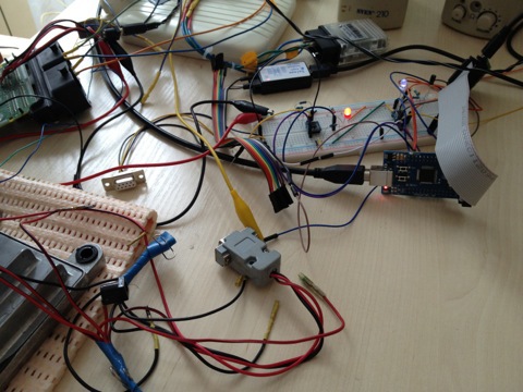
And so on the other hand:

In the laboratory, on the specified test programs, everything worked perfectly. However, before creating a fee for mass production, it was decided to make test non-commercial samples that would be distributed to people ready to take part in testing. Originally, they wanted to make the boards with the help of LUT, but later ordered 10 boards at the factory.
Such testing of course bore fruit. Not even so many bugs were found in the device firmware itself, as it was necessary to adapt the device for programs of various manufacturers, which use the device as an adapter for the J2534.
According to the results of testing, it was already decided to create a board that will go into series. The final scheme of the device was made by my companion, the wiring fee was charged to an outside contractor. On the diagram, the devices were not initially saved - everything that could be protected and made as fail-safe as possible was done.
A separate topic is the device case. This is a topic for a separate topic. Therefore, I will say that at the moment I have stopped at the factory making an acrylic case, and we are planning to complete this device with these cases the other day.
Initially, we delivered the device in a covered transparent cambric, and the board itself was varnished.
I will give a little chronology, in order to be able to understand what it cost.
It should also be said that this is not the only project that has been made in this time frame.
What was used when creating the project:
Secondary hardware for project creation:
As a result, we received a J2534 device that supports the following list of protocols:
Support for the following protocols:

In view of the fact that a number of functions described in J2534 are not used in programs with which it was planned to use the device, it was decided to exclude them. In particular, it supports the J1850 protocols (PWM / VPW). Perhaps, when there is time, I will tighten these protocols into the device in order to get 100% coverage of the J2534 protocol.
I want to share my own experience in developing an electronic device. First, I will tell a little background, so that it is clear why this, in fact, was necessary for me.
How it all began
Initially, we were developing software for chip tuning. One of the main tasks of which is to read the firmware from the computer (electronic engine control unit) and write it back. It is clear that for these purposes you need to somehow connect the computer and the ECU using an adapter. When earlier the overwhelming number of ECUs used the simplest method of receiving and transmitting data, it was enough to use the simplest adapter on transistors or a specialized chip. However, today most cars use the CAN bus to “communicate” their components with the external environment. The adapter for the CAN bus on transistors is no longer assembled, and here you definitely need a processor that will manage everything according to a specific program.
So the first problem arose - how to overcome CAN bus. In order not to reinvent the wheel, the choice is made on the use of a ready-made adapter that works according to the J2534 standard. For those who do not know, the J2534 standard is a standard that describes the hardware and software parts of the device with which you can connect to the computer through a computer. Developed by the Americans. The main reason for its development was the legislative consolidation of the possibility of updating the ECU firmware not by a specialized dealer service, but by anyone. Actually, if everyone can update the firmware on his phone, then why can not he do it with his car.
')
The most affordable import equivalent costs around $ 200. As it turned out later, two identical devices that meet the J2534 standard can work differently with the same software. Therefore, initially had to become attached to a specific manufacturer and its device.
Experiments
Those functions that we needed in the "hardware", were present in the common adapter for diagnosing ELM327. It remains only to write the driver J2534 (in fact, it is a DLL, which serves as an interlayer between the program on the computer and the device itself). I previously contacted the ELM327 developers, but they said that they didn’t have plans to write such a driver, but they were ready to provide free firmware for ELM327. Previously, I had written such a driver that supported only the ISO 11898 (raw CAN) protocol. However, I was disappointed. With a CAN speed of 1Mb / s, ELM327 simply does not have time to receive such a large number of packets, constantly knocking out an error due to overflow of the internal message buffer. In addition, the exchange protocol between the computer and the ELM327 is organized in the form of ASCII messaging (so that it is convenient to work in the terminal). Accordingly, instead of transmitting one byte of data, three are transmitted (two bytes are the display of characters plus a separating space). It turned out that most of the USB traffic was wasted. And considering that the maximum speed of work with ELM327 via USB is 3 Mb / s, then with such an exchange organization, it is not possible to receive 1 Mb / s via CAN bus.
I never liked to depend on anyone, therefore, the idea to create my J2534 adapter did not leave me.
The first steps
I should say here that before developing my J2534 adapter I didn’t have any development experience using a processor, but I had a lot of programming experience. Initially, there were attempts to find artists who could create such a device on a turnkey basis, but they were not crowned with success. Therefore, it was decided to start doing it yourself. First of all, it was necessary to determine the processor. The choice fell on the ARM processor from ST - STM32F105. Criteria for choosing a processor were the distribution, price, and availability of third-party specialists who would help solve the problems encountered as soon as possible. A breadboard from Olimex was purchased as a breadboard. With its help, “labs” were successfully performed for mastering the processor: LED blinking, sound squeaking, displaying on the LCD screen, working with the UART.
I really liked the IDE from CooCox. There were also tests with Keil, but, as they say, “it did not go.”
The working process
As I wrote above, there were attempts to find performers who would do everything on a turnkey basis, but they were not crowned with success. To stretch the development for a long time and did not want to understand everything myself either. Therefore, it was decided to split the task into independent parts, and some of them should be entrusted to developers who had experience in such things. Such a developer was found using freelance exchanges. Actually, a freelancer was required to create a program that controls the processor. The rest of the work related to the development of the final scheme, the printed circuit board and the production order was already to be commissioned by someone. For those who follow my path, I’ll say that the freelancer in this whole process is not a panacea and after that you will have to work on code optimization so that this code does not just work, but be high-quality and extensible.
The contractor immediately suggested that I use RTOS in this project instead of the standard library from STM32. To be honest, was puzzled. I have never dealt with RTOS, and my companion was categorically against using RTOS for this project. In the end, I nevertheless agreed to use RTOS and later did not regret it.
Initially, there were no problems, and separate bricks were made, which are responsible for the exchange between the adapter and the computer via USB, working with the UART, developing its own bootloader, with which you can update the firmware of the device via USB.
Problems began with CAN. Standard drivers for working with CAN ChibiOS (I stopped at this RTOS) use processor slots for storing received messages. There are only three of them, so if you do not have time to choose messages from there, they will simply be lost. So it happened. While the messages were going “slowly” - they were safely received, but as soon as the number of CAN messages per second exceeded thousands, problems started. "Overclock" or optimize reception on the standard driver did not work, so it was decided to completely rewrite it. Those. make software buffer CAN messages instead of hardware. The size of this software buffer was 256 CAN messages, and that turned out to be quite enough.
It was necessary to deal with writing this driver independently, since the performer did not have the technical ability to generate an avalanche-like stream from CAN packets, and there was no desire to look for a new executor and reinstall him in the course of the matter. But all that is not being done is being done for the better, and thanks to the independent development of the driver for ChibiOS, I was able to immerse myself in its study. After that, a number of parts of the project were decided to be done independently, without the involvement of a third party.
Part of the time was spent studying the ISO 15765-4 (CAN), ISO 9141-2 protocols. It should be said that real ECUs helped to quickly deal with them - it was enough to “listen” the exchange of the ECU.
First sample
The first device sample existed in the form of a breadboard with the STM32F105 and a breadboard with the interface L9637D and TJA1050. It looked like the first laboratory sample.
And so on the other hand:
In the laboratory, on the specified test programs, everything worked perfectly. However, before creating a fee for mass production, it was decided to make test non-commercial samples that would be distributed to people ready to take part in testing. Originally, they wanted to make the boards with the help of LUT, but later ordered 10 boards at the factory.
Such testing of course bore fruit. Not even so many bugs were found in the device firmware itself, as it was necessary to adapt the device for programs of various manufacturers, which use the device as an adapter for the J2534.
Final stages
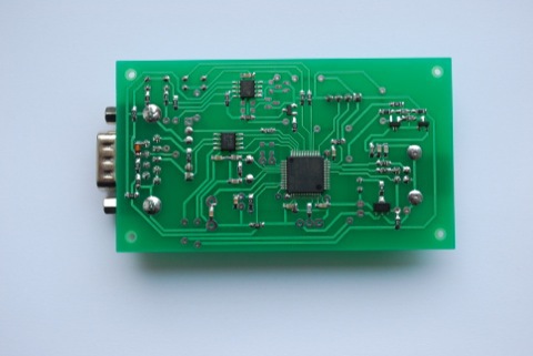
According to the results of testing, it was already decided to create a board that will go into series. The final scheme of the device was made by my companion, the wiring fee was charged to an outside contractor. On the diagram, the devices were not initially saved - everything that could be protected and made as fail-safe as possible was done.
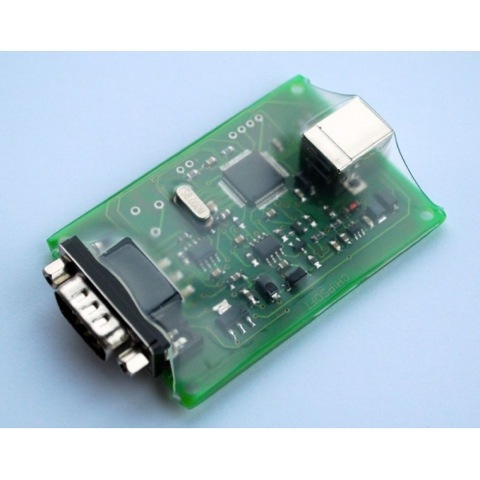
A separate topic is the device case. This is a topic for a separate topic. Therefore, I will say that at the moment I have stopped at the factory making an acrylic case, and we are planning to complete this device with these cases the other day.
Initially, we delivered the device in a covered transparent cambric, and the board itself was varnished.
Results
I will give a little chronology, in order to be able to understand what it cost.
- March 2013 - the first acquaintance with STM32
- June 2013 - start of work
- October 2013 - the first test sample
- January 2014 - official launch of sales
It should also be said that this is not the only project that has been made in this time frame.
What was used when creating the project:
- RTOS ChibiOS
- Sublime Text2
- GCC (CodeSourcery)
Secondary hardware for project creation:
- CAN Hacker
- Saleae Logic Analyzers
- USB-UART converter
As a result, we received a J2534 device that supports the following list of protocols:
Support for the following protocols:
- ISO 11898 (raw CAN) up to 1Mb / s
- ISO 15765-4 (CAN)
- ISO 14230-4 (Keyword Protocol 2000)
- ISO 9141-2
In view of the fact that a number of functions described in J2534 are not used in programs with which it was planned to use the device, it was decided to exclude them. In particular, it supports the J1850 protocols (PWM / VPW). Perhaps, when there is time, I will tighten these protocols into the device in order to get 100% coverage of the J2534 protocol.
Source: https://habr.com/ru/post/224297/
All Articles