As I did the Wi-Fi scales, I did not quit anywhere, but I keep silence about life
From the title it is not difficult to see that this adventure was motivated by the banal desire to smooth the title of the guys from Madrobots . And this was indeed an adventure: the only story with the prolonged purchase of the INA125U is so boring that it can drive anyone but me crazy. However, perhaps I still do not know something about myself.
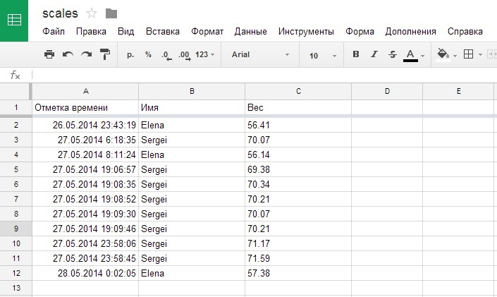
So, the scales. I, as usual, did everything wrong. Namely, I didn’t even look at what representatives of this group, scalar, so to speak, typical of the current development of the Internet of things, can do. Therefore, my scales are able to separately weigh three different individuals of a person (me, a wife, and a spherical guest in a vacuum), as well as five cats. The results are voiced by a nearby smartphone and published in the tablet Google.
')
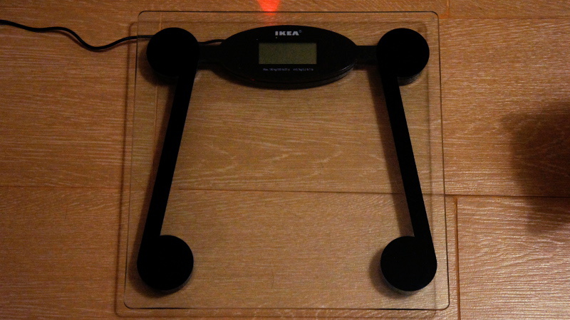
Now, on how to do this, having on hand IKEA scales, TI INA125 operational amplifier, Arduino Pro Mini, Serial converter - Wi-Fi HiLink HLK-RM04, a little bit of other stuff and a hefty awl in the ass.
There is a contact!
Actually, when I bought a Serial converter on Wi-Fi on DX.com, I was not so much fascinated by its capabilities (I had a very vague concept about them then) as by price compared to the same Wi-Fi shield for Arduino. Of course, it soon became clear that the difference in price is not just that: out of the box, this converter resembles a shield a little. And yes, I understand - this is obvious to you, but for me it was a revelation that there will be no GET / POST just like that.
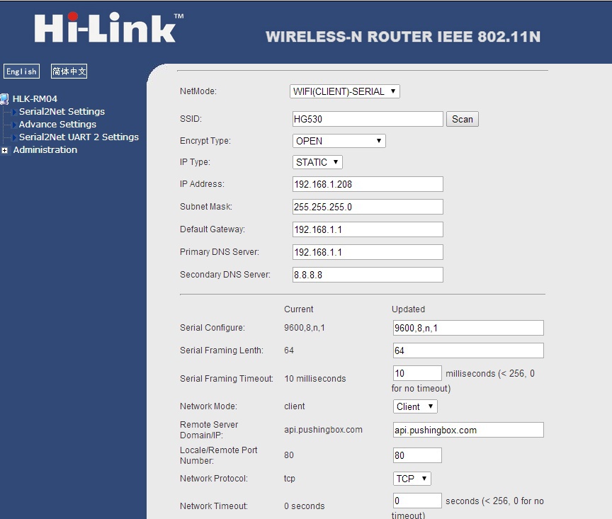
Nevertheless, I almost immediately after the purchase tried the HLK-RM04 in action. At first, without a microcontroller at all. Just plug in the power supply (5V) and go to the default address specified in the manual. In the same place, after some doubts (as if something should not be bungled), I drove in my Wi-Fi settings and issued a static IP to the converter, in order not to search for it all over the network.
These were the settings. Running ahead is a complete set of settings for the scales (IP and SSID substitute your own, but the port speed is quite important - at this speed the HLK-RM04 will communicate with the controller):
At the second stage I connected to the controller and looked at what can be done without a library and without efforts. It turned out that if you switch it to server mode, connect it to the Arduino serial port, and write code that periodically prints something to this very port, then you can see what is printed in the browser. Also, in principle, not bad, but not too inspiring. Nevertheless, I remembered it for the most extreme case.
In general, the HLK-RM04 would be lying in a dusty box if it were not for Madrobots. I considered any options: and make the converter work as a web client, and if it does not work out, then at least take data from it through Tasker on the smartphone, and publish the same Tasker where I need to. Fortunately for the first option, a suitable WiFiRM04 library was found , which ultimately behaves almost like a Wi-Fi library for Arduino.
There is, of course, specificity. This library is built on the Arduino Mega, which has a lot of RAM and serial ports - above the roof. Therefore, the author of the library by default used a broad gesture to use two ports of the Arduino Mega to communicate with the HLK-RM04, and the remainder had a connection to the desktop via USB for simultaneous debugging.
And, by the way, taking into account the default included debug module, even a tiny program with the WiFiRM04 library compiles into a little less than 30KB, so the prospects for migration to the Arduino Pro Mini seemed a bit dubious. However, there is some good news: the author still provided for both work with a single port and turning off the debug module.
About the first is written on GitHub, and I learned about the second from the forum Arduino.cc .
And yet, honestly, I debugged on Mega, because it seemed too dreary to constantly disconnect-connect the HLK-RM04 - after all, it occupies a single port on the Pro Mini, so even for the banal download of a new version of the program, the converter needs to be disabled. But there is also a trick: if, after downloading the program to the Pro Mini, you connect both the HLK-RM04 and the desktop to the port monitor at the same time, you can see what the controller sends to the converter. And this allows us to understand what the state is in general.
The bottom line for adapting WiFiRM04 to the Arduino Pro Mini was:
1) In at_drv.cpp do this:
#define DEFAULT_BAUD1 9600 #define DEFAULT_BAUD2 9600 2) In the same place - like this:
// use Serial1 as default serial port to communicate with WiFi module #define AT_DRV_SERIAL Serial // use Serial2 to communicate the uart2 of our WiFi module #define AT_DRV_SERIAL1 Serial 3) In the same place - comment out #define _DEBUG_
// #define _DEBUG_ 4) In the same place - do not forget to put your favorite digital pin in #define ESCAPE_PIN
#define ESCAPE_PIN 4 3) In wl_definitions.h, change MAX_SOCK_NUM to 1
In both cases, that with Mega, that with Pro Mini, I checked the efficiency of this hybrid with a hedgehog in practice - sent requests to a server that could capture their receipt.
Own burden pulls or pulls
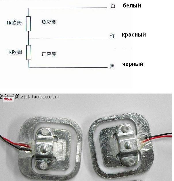
At the next stage, I began to study the issue of obtaining data from the scales. The theory stated that, depending on the type, the scales are completed with one, two or four strain gauges. Having opened the usual Ikeev scales, I realized that here, in general, is the classical scheme: each heel is on the sensor, that is, there are only four sensors. Confused only the number of wires.
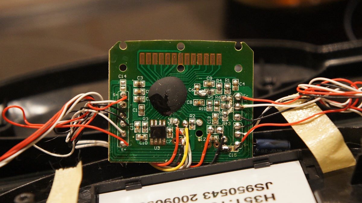
. original scale board
It turned out that each sensor was equipped with these three useful things. However, the same theory stated that, in general, the (constant) resistors have two pins.
. load cell
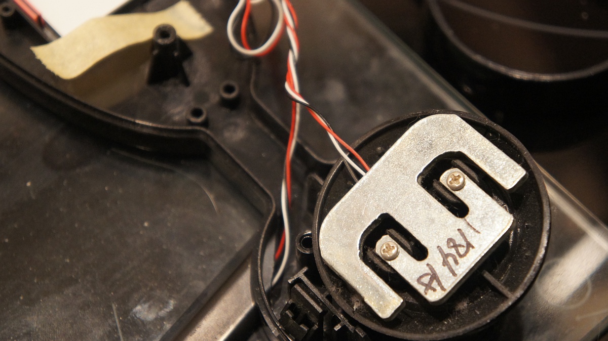
A thoughtful study of Aliexpress revealed the following: sly Chinese are producing sensors in the form of half a rather popular measuring bridge (Witstone Bridge).
The bridge itself looks like this (picture from Wikipedia, the link to which is next):
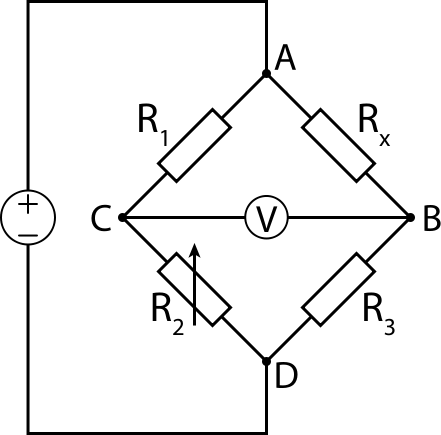
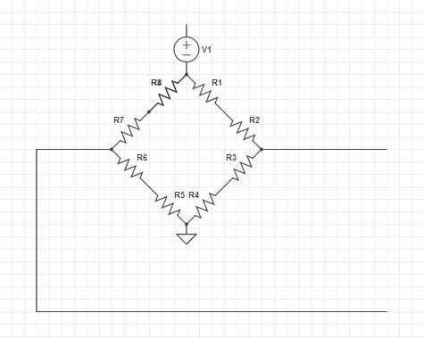
And, in principle, everything was clear. But I could not understand how the four half bridges are connected into one bridge and why it is needed. The answer to the first part of the task was given by the motherboard of the scales. The same Chinese, in order not to waste copper, have connected ready-made common points where necessary: to the current source and to the potential receiver. And everything else was connected so as to get the bridge. As a result, each factory half-shoulder was a quarter shoulder:
Well, okay.
The principle of measuring weight is quite simple: the load changes the resistance of the strain gauges, which naturally results in a change in voltage at the output of the bridge. Moreover, the voltage varies linearly depending on the weight. In general, everything is good, if not for one thing: the output voltage of the bridge is too small to measure it directly to the Arduino ADC. The omnipotent Internet tells us that a suitable amplifier is necessary for success — with a sufficiently large gain, with a fairly small noise.
The same Internet advises the use of instrumental operational amplifier INA125 produced by well-known Texas Instruments. Many of the corresponding circuit solutions repeat each other as a carbon copy and practically do not depart from the classical scheme in the datasheet. And yet I decided to be original and chose to repeat just such a scheme :
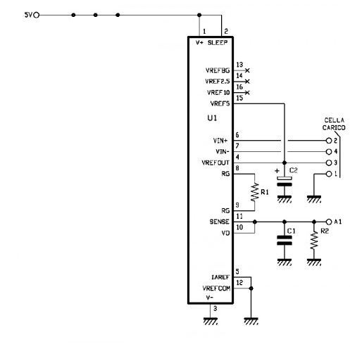
Here R1: 39 Ohm, R2: 1 kΩ, C1: 100 nF, C2: 100 μF. The measuring bridge is connected to the pads 1, 2, 3 and 4, and if I understand at least I don’t need to choose points especially when connecting to the bridge, the main thing is that V +, V-, Vref and GND go through one, t. e., for example: Vref, V +, GND, V-. On the other hand, I subsequently did not take risks, but simply looked at the designations on the motherboard of the scale, there was: E +, E-, S + and S-, and connected it all to the amplifier accordingly (E + = Vref, E- = GND, S + = V +, S- = V-).
It would seem that everything is clear: I bought the parts and sit on the amplifier. However, even in DC it turned out to be somehow hellishly difficult to acquire 1 (One) amplifier TI INA125, and especially - in DIP. Prices range from 100 to 800 rubles, delivery time - from tomorrow to a month, the location of offices and shops is such that even a depression begins to depression.
With the forces I was going for about a month. Then he spat on everything and ordered in Chip-i-Dip boutique, but through their website. Thus saved on seeds: if I am not mistaken, then the minimum batch of 20 resistors was worth almost less than this unfortunate resistor in the offline store. At the same time I found out that SOL16 is much, there is MUCH less than I thought. And just like that in a canopy it does not unsolder
I was almost upset, but I decided to look for some solution to the problem. Found in the same boutique. These are ready-to-use adapter shawls, where the SOL16 cockroach suddenly spreads out onto platforms with a completely sane 2.5 mm pitch. To celebrate, I bought three pieces. Why are they to me - I will not put my mind, all the toad.
. cockroach on the board
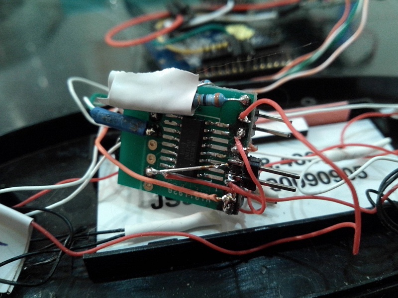
The rest of the details, however, unsoldered vnaves. And foolishly unsoldered forks, as on the Arduino. I thought that I would connect through sockets for simplicity. However, the reality turned out to be more harsh, and as a result I had to roll the plugs, and the whole board was generally tape. Here is another architectural jamb: electrical tape - white.
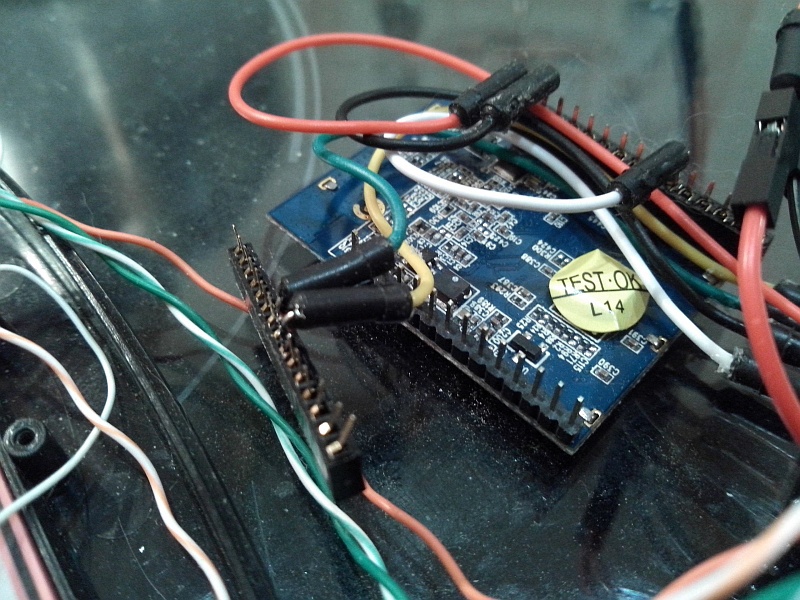
. HLK-RM04 was connected via plugs (2 mm pitch). It turned out to be correct, otherwise I would be tormented by soldering and soldering: after all, during debugging, you need to disconnect from the module in order to release the controller port
Surprisingly (I am always surprised when something that came out from under my hands works), but the finished board, connected to the scales and to the Arduino, began to produce adequate results. So now I had all the components of the scales in my hands: a scale with a voltage converter and a controller with a communication unit. Therefore, I dropped the pathos and called the first version of the program alpha. As it turned out - not in vain.
. almost beta: alpha used an LED on the controller board

In principle, the alpha worked well, while the controller was connected to a computer (at that time I used either the Mega or the Pro Mini, but without the HLK-RM04, for the reason mentioned above, the lack of serial ports). However, when switching to autonomous power, there was a feeling that the whole structure had gone mad. A small investigation revealed that I was again confronted with a problem familiar from the Automatic Light and Music Machine ASIM-AU-2-6 . Namely - constant fluctuations of values when reading the analog pin of the controller, which I associate with the pulsed nature of the power supply.
You can admire these very fluctuations at rest
17.05.2014 23:55:51 user 28 17.05.2014 23:56:03 user 21 17.05.2014 23:56:28 user 11 17.05.2014 23:56:41 user 58 17.05.2014 23:56:53 user 10 17.05.2014 23:57:05 user 22 17.05.2014 23:57:18 user 30 17.05.2014 23:57:30 user 26 17.05.2014 23:57:42 user 9 17.05.2014 23:57:55 user 22 17.05.2014 23:58:07 user 28 17.05.2014 23:58:20 user 22 17.05.2014 23:58:32 user 29 17.05.2014 23:58:45 user 13 17.05.2014 23:58:57 user 26 17.05.2014 23:59:10 user 22 17.05.2014 23:59:22 user 44 17.05.2014 23:59:34 user 22 17.05.2014 23:59:47 user 58 17.05.2014 23:59:59 user 13 18.05.2014 0:00:11 user 29 18.05.2014 0:00:24 user 14 18.05.2014 0:00:36 user 51 18.05.2014 0:00:49 user 22 18.05.2014 0:01:01 user 11 18.05.2014 0:01:14 user 30 18.05.2014 0:01:26 user 27 18.05.2014 0:01:38 user 9 18.05.2014 0:01:51 user 29 18.05.2014 0:02:03 user 28 18.05.2014 0:02:16 user 9 18.05.2014 0:02:41 user 22 18.05.2014 0:02:53 user 8 18.05.2014 0:03:06 user 28 18.05.2014 0:03:18 user 27 18.05.2014 0:03:30 user 22 18.05.2014 0:03:43 user 27 18.05.2014 0:03:55 user 31 18.05.2014 0:04:07 user 22 18.05.2014 0:04:20 user 28 18.05.2014 0:04:32 user 22 18.05.2014 0:04:45 user 10 18.05.2014 0:04:57 user 24 18.05.2014 0:05:09 user 27 18.05.2014 0:05:22 user 22 18.05.2014 0:05:34 user 27 18.05.2014 0:05:47 user 23 18.05.2014 0:05:59 user 22 18.05.2014 0:06:12 user 14 18.05.2014 0:06:24 user 28 18.05.2014 0:06:36 user 59 18.05.2014 0:06:49 user 55 18.05.2014 0:07:01 user 27 18.05.2014 0:07:14 user 58 18.05.2014 0:07:26 user 27 18.05.2014 0:07:38 user 22 18.05.2014 0:07:51 user 24 18.05.2014 0:08:03 user 28 18.05.2014 0:08:16 user 57 18.05.2014 0:08:28 user 28 18.05.2014 0:08:53 user 28 18.05.2014 0:09:05 user 28 18.05.2014 0:09:18 user 24 18.05.2014 0:09:30 user 23 18.05.2014 0:09:43 user 8 18.05.2014 0:09:55 user 28 18.05.2014 0:10:07 user 13 18.05.2014 0:10:20 user 22 18.05.2014 0:10:32 user 36 18.05.2014 0:10:45 user 30 18.05.2014 0:10:57 user 26 18.05.2014 0:11:10 user 59 18.05.2014 0:11:22 user 57 18.05.2014 0:11:34 user 29 18.05.2014 0:11:47 user 27 18.05.2014 0:11:59 user 27 18.05.2014 0:12:11 user 28 18.05.2014 0:12:24 user 27 18.05.2014 0:12:36 user 17 18.05.2014 0:12:49 user 11 18.05.2014 0:13:01 user 21 18.05.2014 0:13:14 user 53 18.05.2014 0:13:26 user 54 18.05.2014 0:13:38 user 56 Studying the forum Arduino.cc showed that I am not the only one so happy. One of the recommended methods of dealing with this effect is to pull the analog pin to the ground, using wires of the minimum length. But my wires were no longer than 10 centimeters, and the analog pin, as you can easily see from the circuit, is already pulled to the ground. Therefore, I had to turn to a proven method: first, I added a certain threshold weight to the program, which is obviously more than the observed fluctuations. And, secondly, since the fluctuations were too noticeable, I calculated the weight as the average of a sufficiently large, although not infinitely large, number of measurements. More specifically, I average a thousand measurements, which more or less leads fluctuations (and values in general) to more or less reasonable limits.
But this was not the only problem. I was so used to relying on other people's schemes that at first I did not understand why at some point the scales begin to show the same value. And then it became clear: this is the measurement ceiling. I am not a genius, so I spent quite a lot of time finding out this simple fact and solving the problem.
The problem is that the gain of the INA125 is given by the resistor R1 according to the formula:
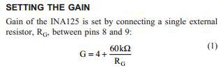
Thus, the gain according to the authors of the scheme is set at 1500 (1542.5, more precisely). Apparently, it was selected for a specific copy of the scales, which I did not think about. For my scales, judging by the results, it turned out too. So I added another 39 Ohm resistor and got a slightly different result: a gain around 773.
It should be remembered that, based on the same INA125 datasheet , the voltage at the output of the amplifier does not exceed 3.8V. From here we get the maximum reading value of the Arduino analog pin: (3.8 * 1024) / 5 = 778. By this time I also had time to attach myself to the weights, so I found out that the ratio between the weight and the value on the analog pin is about 7.25.
Summary: with the current gain, the theoretical measurement limit of the weights is about 107 kg, which suits me more than that. But if there is something to disturb, then, probably, I will change the resistor and get to the operational boundary of 150 kg. And the post-summary for the curious. Scales I calibrated for other floor scales. It is clear that the accuracy there is plus or minus sneakers, well, so the original, it is the same.
No reference scales used. Just three measurements on one, three measurements on others. And the arithmetic mean of each instance is divided by each other. Hence the ratio between what gets the Arduino and the actual weight.
One for all
So, I had calibrated scales and pieces of iron capable of transferring readings ... somewhere, in general, capable. It remains quite a bit: to write a work program with multi-user multi-view mode and, if possible, a more or less convenient way to switch views and users.
The explanation is simple. I wanted to get identifiable weighing results for myself, my wife, and let the guests play around without mixing their results with mine. And sometimes I would like to weigh our cats, and with a minimum of effort. You know how cats are weighed, right? You take the cat in your arms, stand on the scales, remember the weight, release the cat, again stand on the scales. Then subtract less from more.
In general, word for word, and two types (people and cats) and eight users were defined. Therefore, I recall, more or less convenient management was highly desirable.
I refused the idea of using a native LCD display almost immediately, as I read about reverse engineering of the communication protocol with it. And on the occasion of a 0.96-inch OLED screen, I managed to kill somewhere in the process of experiments (probably, it was still at 3.3V, and not at 5V, as the Chinese promised). Yes, and in honor, I terribly screwed up: on the photo the display seemed rather large, but in fact turned out to be tiny - nothing would have been seen from the height of growth anyway. In addition, I found out at the testing stage that the display library and the WiFiRM04 library do not get along. Obviously, the Pro Mini has too little memory for them.
Therefore, from the output means remained tweeters and LEDs. Lyrical digression: now a segment LED display is coming to me, which, perhaps, I will bolt to the weights, but perhaps not - I like too much what happened. With the LED, I planned to show the readiness of the scales to work, and with a squeaker, to voice the current status, successfully send readings and errors.
As for input tools, I wanted to get by with the absolute minimum. Just imagine: you are standing on the scales, and some other buttons, switches - what is it for? At the same time, we didn’t want to be chained to the smartphone, assuming that the desired setting would be activated by the smartphone. That is, ideally, management according to my idea should be such that even in the middle of the night with eyes closed it would be possible to weigh without questions.
And then I thought: “Hey, man, you have four beautiful weight sensors under your feet (well, ok, one is synthetic). Why not use them as an omnipotent button? ” Honestly, half the personality (active) was delighted with such an elegant solution to the problem; the second half (lazy) is in deep sorrow. But the idea was fascinated, and after some time of trial and error, the following control concept appeared: switching modes and users by pressing the weights table, and displaying the current status with sound signals.
In general, the "menu" is something like this:
1) The first pressing after weighing or immediately after switching on reports the current status;
2) Subsequent single clicks switch users within the category;
3) Press twice to switch modes (people / cats);
4) Press three times to reset the settings to default values.
Sound indication is also quite simple. One long signal means people, two long ones - cats. The subsequent number of short signals is the number of the user in the queue. In this version of Morse code, for example, dash-point-point means that we weigh the number two person; and the dash-dash-dot is the number one cat.
Of course, it is enough to press the toe on the weights table (and there is nothing to crawl on on all fours). And, of course, time intervals for clicks and audio signals are selected so that it is comfortable for control and perception. Those. there is an acoustic feedback click and a sufficient pause to have time to press several times in a row for the timeout allotted for the command.
There was only a little bit - somehow find out your own weight. And for this, I used clever Internet services, and therefore the weight announces the nearest Android-device (tablet there or a smartphone). In theory, you can cross with iOS, but I have nothing to check. The delay is extremely small, and taking into account the fact that these are generally scales, which should not work without the Internet, the concept is quite viable.
Is there life after HTTPS or how to make the scales talk
The results of measurements, I immediately planned to lay out on the Internet. Just as I do with the current climate at home and near it. But for a number of reasons, my beloved People’s Monitoring was not suitable for this purpose. But Google tables were quite suitable, but they required connection via HTTPS, which the Arduino cannot pull out in any way - neither with the native network shield, nor, especially, with the non-native.
But it turned out that there is a very attractive solution - the Pushing Box service, this is all a special notification for the Internet of things, according to the description. And she, clever, takes all this SSL-magic on herself. And the study of the same Google led to the recipe for crossing the Arduino and Google tables, and here it is also important about the Submit button .
In a nutshell: make a form in Google, get an account on the Pushing Box. Then in the Pushing Box:
1) Add a Google form as a CustomURL service, where the URL should be:
https://docs.google.com/forms/d/ID /formResponse 
2) Add a script that looks like this:
?entry.11234123=$status$&&submit=Submit Here entry.11234123 is the name of the form field, which can be viewed in its source code. multiple fields, as usual, are combined via &.
3) From the Arduino code (or whatever you have) adding data is HTTP-POST / GET of the following type:
http://api.pushingbox.com/pushingbox?devid=v0123456789ABCDE&status=open Here devid is the identifier given by the Pushing Box, “open” is the value to be passed.
Returning to the announcement of the results. This is done by a bunch of Pushing Box and Newtifry , which exists in two ways: the Pushing Box service and the App for Android (there is a similar service for iOS).
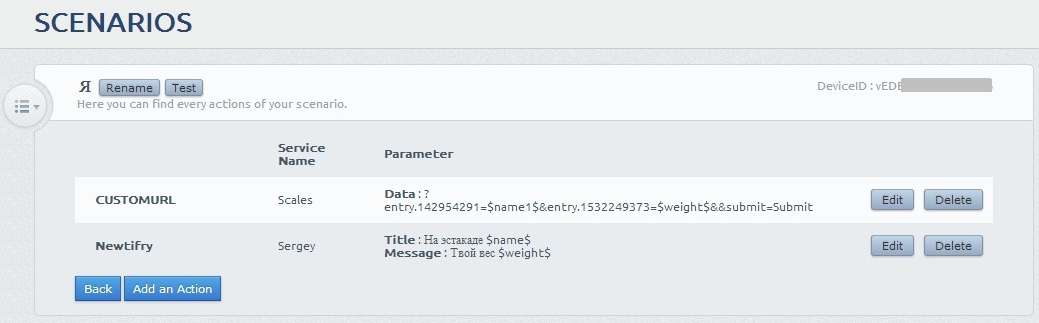
And I started several scenarios at once - one for each user-person and one common for cats. Just so that you can then flexibly configure whose smartphone and when announces the weight.
As a result, my HTTP request to the Pushing Box looks like this:
http://api.pushingbox.com/pushingbox?devid=v0123456789ABCDE&name=&name1=username&weight=99.9 String suffered. It turned out that Newtifry perfectly conveys the Cyrillic TTS Android, but the same Cyrillic turns into cracks in the Google table. Therefore, I give the same name to the Pushing Box twice: Cyrillic and Latin. The first through Newtifry is sounded by the smartphone, and the second through CustomURL is sent to the table.
By the way, Google automatically marks the time stamp, so my head does not hurt about it:
And after some thoughts and consultations with the author of the People’s Monitoring, I still connected him to the scales. Which is typical, through the same Pushing Box, which eventually became a kind of data hub-repeater.
Everything turned out to be very simple. Suppose that you already have accounts on the Pushig Box and People Monitoring. Then first go to the Pushing Box and add another CustomURL to the services:
http://narodmon.ru/post.php Method: GET
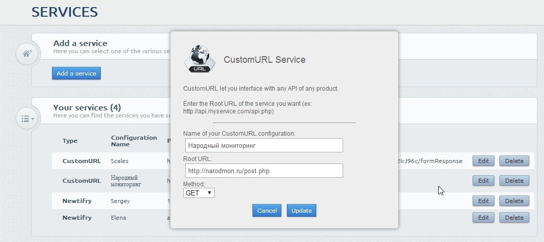
Then we go to the script and create a new one or add to the existing new action - the just created CustomURL. And in the Data row add the rest of the query:
?ID=0123456789AB&AB9876543210=$weight$ 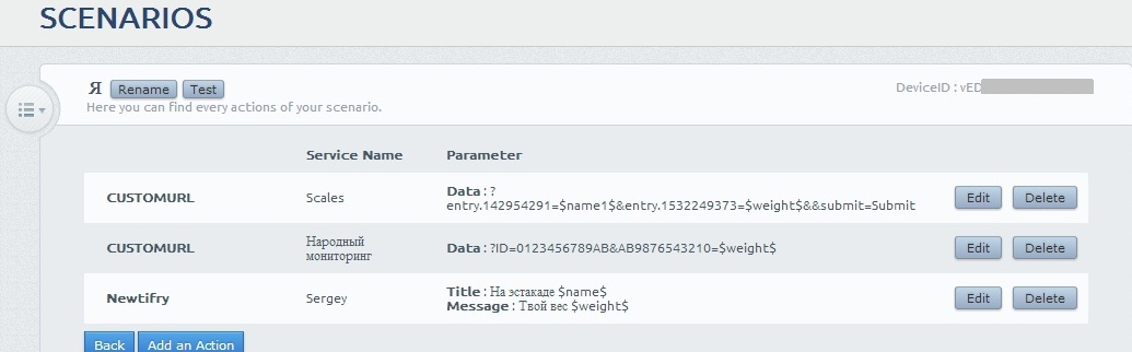
Here, in terms of People Monitoring, the ID is your device ID, and the next number is the sensor ID. Accordingly, sensors can be made available to all available users. However, in the context of my implementation of scales, one sensor is equivalent to one group of users, of which there are only four: one for each person and one for all cats (yes, discrimination, but you can correct it if you want).
Well, $ weight $ is a weight well known to you, which the Pushing Box receives from the scales and sends what they say.
Design
In my configuration to build the scales will require:
1) Scales with 4 strain gauges. As I understand it, this is a fairly popular design now, but I can not guarantee that everyone is made that way. The important point: the clearance of the scales must be such, or the scales must have such a body that all the electronics fit into it. Otherwise you will have to put the box next to it.
2) Converter Serial-Wi-Fi HLK-RM04. Here, for example .
3) INA125 , .
4) ( 100 , 100 , 1 , ).
5)
6) . — , ( ). , , .
7) Arduino Pro Mini. , .
8) , 5 .
:
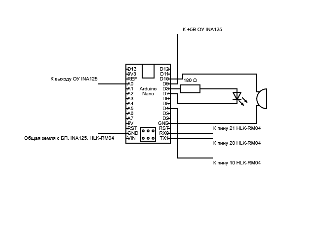
. , Arduino nano. , , — Pro Mini.
, .
INA125 . R1 . , , .
— . . , .
, — , , - . . , , — .
Algorithm
, , . — , . , .
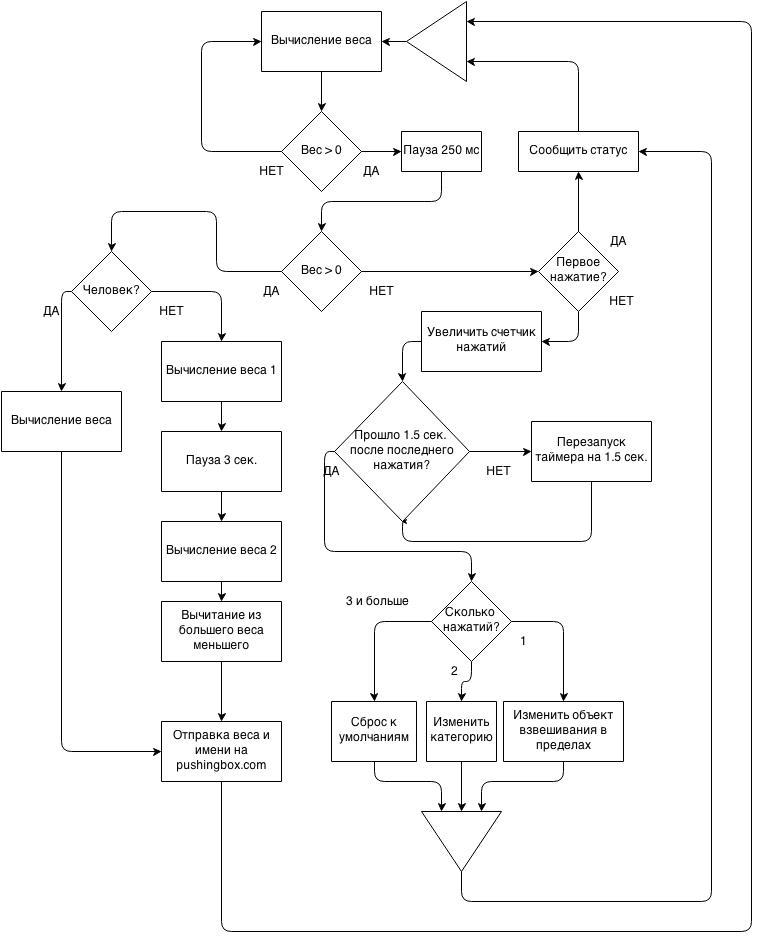
. :
1) tare — «»
2) treshold — ( )
3) Arduino . — 7.25, sendWeight
Secret code
#include <avr/pgmspace.h> // PROGMEM #include <SimpleTimer.h> // http://playground.arduino.cc//Code/SimpleTimer #include <WiFiRM04.h> char ssid[] = "YOUR SSID"; // your network SSID (name) char pass[] = "YOUR NETWORK KEY"; // your network password (use for WPA, or use as key for WEP) int keyIndex = 0; // your network key Index number (needed only for WEP) int status = WL_IDLE_STATUS; char server[] = "api.pushingbox.com"; // name address for Google (using DNS) WiFiRM04Client client; #define ledPin 8 #define weightPin A0 #define tonePin 10 #define weightPowerPin 9 byte tare = 28; // idle weight byte treshold = 30; // weight sensor value treshold int i; int scaleTimeoutID; byte nameSelectorCount = 0; // counter for name selection byte stepCount = 0; byte human = 0; // default setting byte cat = 0; // default setting float wt; long weight, brutto, netto; long prevWeight = 0; boolean idleWeight = false; boolean clearToSend = false; boolean ishuman = true; boolean nameSelect = false; boolean stepCounting = false; boolean stepTimeout = false; boolean firstStep = true; // PROGMEM prog_char statusString_0[] PROGMEM = "devid1&name="; // User 1 prog_char statusString_1[] PROGMEM = "devid2&name="; // User 2 prog_char statusString_2[] PROGMEM = "devid3&name="; // User 3 prog_char statusString_3[] PROGMEM = "devid4&name="; // Cats prog_char statusString_4[] PROGMEM = " 1"; // cyrillic names prog_char statusString_5[] PROGMEM = " 2"; prog_char statusString_6[] PROGMEM = " 3"; prog_char statusString_7[] PROGMEM = " 1"; prog_char statusString_8[] PROGMEM = " 2"; prog_char statusString_9[] PROGMEM = " 3"; prog_char statusString_10[] PROGMEM = " 4"; prog_char statusString_11[] PROGMEM = " 5"; prog_char statusString_12[] PROGMEM = "&name1=User 1"; // latin names for Google Spreadsheet prog_char statusString_13[] PROGMEM = "&name1=User 2"; prog_char statusString_14[] PROGMEM = "&name1=User 3"; prog_char statusString_15[] PROGMEM = "&name1=Cat 1"; prog_char statusString_16[] PROGMEM = "&name1=Cat 2"; prog_char statusString_17[] PROGMEM = "&name1=Cat 3"; prog_char statusString_18[] PROGMEM = "&name1=Cat 4"; prog_char statusString_19[] PROGMEM = "&name1=Cat 5"; prog_char statusString_20[] PROGMEM = " HTTP/1.1"; prog_char statusString_21[] PROGMEM = "Host: api.pushingbox.com"; prog_char statusString_22[] PROGMEM = "User-Agent: Arduino"; // PROGMEM const char *statusString[] = { statusString_0, statusString_1, statusString_2, statusString_3, statusString_4, statusString_5, statusString_6, statusString_7, statusString_8, statusString_9, statusString_10, statusString_11, statusString_12, statusString_13, statusString_14, statusString_15, statusString_16, statusString_17, statusString_18, statusString_19, statusString_20, statusString_21, statusString_22}; char statusStringBuf[40]; // SimpleTimer scaleTime; void setup() { Serial.begin(9600); pinMode(weightPowerPin, OUTPUT); digitalWrite(weightPowerPin, HIGH); pinMode(weightPin, INPUT); // weight sensor pinMode(ledPin, OUTPUT); // led Power pinMode(7, OUTPUT); digitalWrite(7, LOW); // led GND // check for the presence of the shield: if (WiFi.status() == WL_NO_SHIELD) { while(true) { } } // attempt to connect to Wifi network: while (status != WL_CONNECTED) { // Connect to WPA/WPA2 network. Change this line if using open or WEP network: status = WiFi.begin(ssid, pass); // wait 10 seconds for connection: delay(10000); } } void loop() { scaleTime.run(); averageWeight(); // CHECK FOR IDLE WEIGHT if ((idleWeight == false) && (weight < (tare+treshold))) { // check if there is still somebody on table idleWeight = true; // set flag to enable measurements in case there is nobody on table digitalWrite(ledPin, HIGH); // turn on ready led } // DETECT STEP-ON if ((idleWeight == true) && (weight > (tare+treshold))) { // check if there is still somebody on table idleWeight = false; digitalWrite(ledPin, LOW); // turn on ready led tone(tonePin, 450, 100); // audio confirmation for step-on if (stepCounting == false) { scaleTime.setTimeout(250, stepDetector); stepCounting = true; } } // READY TO SEND if (clearToSend == true) { // check for upload permission sendWeight(); // upload } } // Detect step-on void stepDetector() { averageWeight(); if (weight < (tare+treshold)) { // step detected if (firstStep == false) { // do not count first step stepCount = stepCount + 1; // count step-ons: only announce current name after first step-on; switch names on consecutive step-ons. if (stepTimeout == false) { // set timeout to confirm last step: ie if no one steps on table for specified time, scales must switch to stby or weighing mode scaleTimeoutID = scaleTime.setTimeout(1500, stepTotal); stepTimeout = true; } // tone(tonePin, 450, 100); // audio confirmation for step-on if (stepTimeout == true) { scaleTime.restartTimer(scaleTimeoutID); } } else { statusNotify(); // announce current status stepCount = 0; } firstStep = false; } else { if (ishuman == true) { getWeight(); netto = weight; } else { getWeight(); if (clearToSend == true) { brutto = weight; tone(tonePin, 550, 800); delay(3000); getWeight(); if (brutto > weight) { netto = brutto - weight; } else { netto = weight - brutto; } netto = netto+29; } } } stepCounting = false; } void stepTotal() { // tone(tonePin, 550, 1000); if (stepCount == 1) { if (ishuman == true) { human = human+1; if (human > 2) { human = 0; } } else { cat = cat+1; if (cat > 4) { cat = 0; } } } if (stepCount == 2) { if (ishuman == true) { ishuman = false; } else { ishuman = true; } } if (stepCount > 2) { ishuman = true; human = 0; cat = 0; firstStep = true; } delay(1500); statusNotify(); stepTimeout = false; stepCount = 0; } void statusNotify() { if (ishuman == true) { tone (tonePin, 550, 600); delay(800); makeSound(human+1, 300); } else { tone (tonePin, 550, 600); delay(1000); tone (tonePin, 550, 600); delay(1000); makeSound(cat+1, 300); } } // MEASURE WEIGHT void getWeight() { averageWeight(); if (weight > (tare+treshold)) { // object on table still heavier than idle weight digitalWrite(ledPin, LOW); // turn off ready led delay(3000); // let everything settle averageWeight(); prevWeight = weight; // save initial weight for future reference averageWeight(); if ((((prevWeight - treshold) < weight) && (weight < (prevWeight + treshold))) && prevWeight > (tare)) { // check if measurement average consistent with initial load (ensure object is on table) clearToSend = true; // set flag for upload } else { makeSound(2, 300); // measurement error clearToSend = false; // prevent upload idleWeight = false; // set flag to grant subsequent measurements } } } // HTTP SENDER void sendWeight() { netto = netto - tare; wt = (float)netto / 7.25; if (client.connect(server, 80)) { client.print("GET /pushingbox?devid="); if (ishuman == true) { strcpy_P(statusStringBuf, (char*)pgm_read_word(&(statusString[human]))); // devid client.print(statusStringBuf); strcpy_P(statusStringBuf, (char*)pgm_read_word(&(statusString[human+4]))); // name - name for audio notificaion client.print(statusStringBuf); strcpy_P(statusStringBuf, (char*)pgm_read_word(&(statusString[human+12]))); // name1 - name for Google client.print(statusStringBuf); } else { strcpy_P(statusStringBuf, (char*)pgm_read_word(&(statusString[3]))); // devid client.print(statusStringBuf); strcpy_P(statusStringBuf, (char*)pgm_read_word(&(statusString[cat+7]))); // name - name for audio notificaion client.print(statusStringBuf); strcpy_P(statusStringBuf, (char*)pgm_read_word(&(statusString[cat+15]))); // name1 - name for Google client.print(statusStringBuf); } client.print("&weight="); client.print(wt); for (byte clientCounter=20; clientCounter<23; clientCounter++) { strcpy_P(statusStringBuf, (char*)pgm_read_word(&(statusString[clientCounter]))); client.println(statusStringBuf); } client.println(); client.stop(); makeSound(3, 300); // confirm upload } else { makeSound(2, 300); // upload error } clearToSend = false; // clear flag firstStep = true; } // BEEPER void makeSound(byte count, byte duration) { for (i = 0; i<count; i++) { tone(tonePin, 550, duration); delay(600); } } // CALCULATE AVERAGE WEIGHT void averageWeight() { weight = 0; for (i = 0; i<999; i++) { weight = weight+analogRead(weightPin); // capture measurements } weight = (weight/1000); // measurement average } , , . : , , . , . . , , :)
, . , . -, — . , -, , Wi-Fi WiFiRM04 , , . ? HLK-RM04 — 140 Only Wi-Fi.
.
PS , , — , -, .
Source: https://habr.com/ru/post/224137/
All Articles