Order-Independent Transparency algorithm using link lists on Direct3D 11 and OpenGL 4
 The implementation of order-independent transparency (OIT) can probably be considered a classic computer graphics programming task. In fact, the OIT algorithms solve one simple application problem - how to draw a set of translucent objects so as not to worry about the order of their drawing. The rules for mixing colors during rendering require us to have translucent objects drawn in order from far to near, but this is difficult to achieve in the case of extended objects or objects of complex shape. The implementation of one of the most advanced algorithms, OIT using linked lists, was presented by AMD for Direct3D 11 back in 2010. Frankly, the performance of the algorithm on the widely available graphics cards of those years did not impress me properly. 4 years have passed, I dug up the AMD presentation and decided to implement the algorithm not only on Direct3D 11, but also on OpenGL 4.3. Those to whom it is interesting that it turned out from this invention, I ask under kat.
Before you start talking about the implementation of the algorithm itself, I note that the demo is available to a wide audience here . The project is called Demo_OIT. You will need Visual Studio 2012/2013 and CMake to build. Useful terminology is provided at the end of the post.
Overview of OIT Algorithms
Rendering of translucent objects has a number of features:
- When rendering opaque objects, faces that are not visible to the observer are usually discarded. This allows you to save on rasterization and processing fragments. In the case of translucent objects, reverse faces cannot be dropped;
- The depth test should not be conducted among semi-transparent objects, since some semi-transparent objects can be seen through others. However, the depth of the opaque part of the scene must be taken into account, since an opaque object may partially or completely overlap the translucent;
- It is necessary to draw translucent objects in order from the far to the near. This is dictated by the rules of mixing colors by alpha channel (alpha blending). As already noted, the OIT algorithms can get rid of this limitation.
The generalized OIT algorithm can be represented as follows:
- Draw opaque objects of the scene, save the depth buffer;
- For each fragment of a translucent object, using the depth buffer obtained in step 1, determine whether it is necessary to draw this fragment;
- For each displayed translucent fragment, keep its color, depth and position on the screen;
- For translucent fragments, sort by the depth value from the far to the nearest;
- Draw translucent fragments in the resulting order, mixing their colors according to the value of the alpha channel.
The main difficulty here are items 3 and 4, namely, how to get fragments with different depths, where to save and how to sort.
- The Depth Peeling algorithm (and its variations Reverse Depth Peeling , Dual Depth Peeling , etc.) allows you to get a scene by layers. In the first layer, the fragments closest to the observer are stored, in the second layer - the second closest ones, etc. In the classical implementation, each layer has its own texture, and the translucent part of the scene is drawn as many times as necessary layers. Sorting fragments explicitly does not need enough to mix layers from the far to the near. The disadvantages of the algorithm include the repeated drawing of the scene, the need to store the texture for each layer (not for all variations of the algorithm, this is true), a selection of many textures when mixing colors. The advantage of the algorithm is that it can be implemented even on Direct3D 9.
- The Stencil Routed A-Buffer algorithm assumes the storage of scene layers in an MSAA texture. This algorithm is faster, eliminates the need for multiple drawing of translucent objects, but it deprives us of the built-in anti-aliasing. In addition, the number of MSAA levels is limited (up to 8x-16x on most modern equipment), and therefore the number of layers is limited. I once implemented this algorithm, the details, if interesting, here .
- The OIT using Linked Lists algorithm, to which this post is dedicated, is devoid of the drawbacks of the above described algorithms. Here, the translucent part of the scene is drawn once, MSAA support is possible. The implementation of the algorithm on Direct3D 11 using compute shaders without MSAA support can be found here , there is also a slightly more detailed description of the algorithm.
Implement the Order-Independent Transparency using Linked Lists algorithm
To begin with, I define the requirements for implementation:
- The algorithm works on Direct3D 11 and OpenGL 4.3;
- The algorithm does not use compute shaders. Quite a fragmentary shader;
- The algorithm supports MSAA.
The main essence of the algorithm is as follows: for each displayed semi-transparent fragment, we form a coherent list of fragments, which are located in the same position on the screen. To form such a set of linked lists allows the possibility of modern graphic equipment to conduct an arbitrary record in a dedicated memory block directly from the shaders. Having such linked lists for each translucent fragment, you can sort the fragments by depth and then mix the colors in the correct order.
To implement the algorithm, we need:
- An integer format (unsigned int) that is the same size as the screen for storing head elements of linked lists;
- Buffer in memory for storing linked list items. The minimum content of a linked list element includes the fragment color, depth, and a link to the next element (the address in the buffer);
- The counter of translucent fragments in order to determine the nearest free element in the buffer.
For a better understanding of the principle of operation, consider the following figure.
')
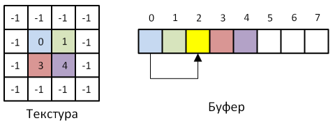
In the figure we see the texture for storing the head elements of the list, in which the addresses of the corresponding fragments in the buffer are stored, and the buffer itself. Places where there are no translucent fragments contain -1. If several translucent fragments had to be in one position on the screen, a list is formed (the fragment with index 0 contains a link to the fragment with index 2). The count of fragments in this situation is 5, i.e. the next fragment will be written to the buffer at address 5, and the counter is incremented.
At first glance it seems that everything is simple, let's move on to the implementation details.
Implementation on Direct3D 11
To implement this algorithm on Direct3D 11, we need the so-called Unordered-Access resources: a texture ( RWTexture2D ) and a structured buffer ( RWStructuredBuffer ). The peculiarity of these resources is that they are read and written in shaders. For them, there is a special set of commands in the Direct3D API, for example, to associate UA resources with variables in shaders, use the OMSetRenderTargetsAndUnorderedAccessViews method. This method is not mentioned randomly. The organization of Direct3D 11 is such that UA resources compete with render targets when they form a bundle with pixel shaders, i.e. if the equipment provides MRT in 8 textures, and 2 slots occupy the render target, then no more than 6 slots remain for UA resources. Work with UA-resources should be done using atomic operations, due to the highly parallel architecture of the GPU.
The fragment count will be implemented using the D3D11_BUFFER_UAV_FLAG_COUNTER flag for the structured buffer. Direct3D 11 allows you to attach an atomic counter to a structured buffer; in our case, it is logical to use a buffer to store the elements of linked lists.
To implement the algorithm on Direct3D 11, create:
- Texture to store the addresses of the head elements of the lists. Format - DXGI_FORMAT_R32_UINT , flags for communicating with shaders - D3D11_BIND_UNORDERED_ACCESS | D3D11_BIND_SHADER_RESOURCE , size is equivalent to the size of the back buffer;
- Structured buffer for storing linked list items. Each list item on the HLSL is represented by the following structure:
struct ListNode { uint packedColor; uint depthAndCoverage; uint next; };
Thus, each item in the list is 12 bytes. There are several such elements for each fragment of the back buffer. Let us imagine a situation where right in front of the camera there are 8 parallel semitransparent planes that occupy the entire screen. In this case, for each fragment of the back buffer a list of 8 elements will be formed. To store this amount of data, you need a buffer of 12 * W * H * 8 bytes, where W, H is the length and width of the back buffer. A rare computer game requires so many visible translucent fragments in a frame, so we take these 8 planes as a limiting case. For a 1920x1080 back buffer resolution, the size of a structured buffer will be approximately 190MB. Attach the fragment counter to the same buffer using the flag described above.
We will draw the frame as follows:
- Clear the texture of the addresses of the head elements of the lists with the value 0xffffffff. For this there is a special method ClearUnorderedAccessViewUint . We reset the fragment counter;
- Set the back buffer as the zero render target, index 1 will receive the head element texture, index 2 - structured list element buffer;
- We are drawing the opaque part of the scene (a skybox and several opaque kettles are drawn in the demo);
- We create lists of fragments of the translucent part of the scene. In order to succeed, it is necessary to disable the cut-off of reverse faces ( D3D11_CULL_NONE ), disable the recording of new values in the depth buffer (but do not disable the depth test), disable the recording of color in the texture (we have nothing to draw at this step, we only create lists). The pixel shader that forms the fragment lists is shown below.
#include <common.h.hlsl> #include <pscommon.h.hlsl> struct ListNode { uint packedColor; uint depthAndCoverage; uint next; }; globallycoherent RWTexture2D<uint> headBuffer; globallycoherent RWStructuredBuffer<ListNode> fragmentsList; uint packColor(float4 color) { return (uint(color.r * 255) << 24) | (uint(color.g * 255) << 16) | (uint(color.b * 255) << 8) | uint(color.a * 255); } [earlydepthstencil] float4 main(VS_OUTPUT input, uint coverage : SV_COVERAGE, bool frontFace : SV_IsFrontFace) : SV_TARGET { float4 color = computeColorTransparent(input, frontFace); uint newHeadBufferValue = fragmentsList.IncrementCounter(); if (newHeadBufferValue == 0xffffffff) { return float4(0, 0, 0, 0); } uint2 upos = uint2(input.position.xy); uint previosHeadBufferValue; InterlockedExchange(headBuffer[upos], newHeadBufferValue, previosHeadBufferValue); uint currentDepth = f32tof16(input.worldPos.w); ListNode node; node.packedColor = packColor(float4(color.rgb, color.a)); node.depthAndCoverage = currentDepth | (coverage << 16); node.next = previosHeadBufferValue; fragmentsList[newHeadBufferValue] = node; return float4(0, 0, 0, 0); }
Consider the most interesting places in this code. The earlydepthstencil modifier plays a very important role. The fact is that the fragment tests (depth test, stencil, etc.) are usually performed at the final stage of the graphics pipeline, after the pixel shaders are executed. In our case, this is unacceptable, since all the fragments drawn at this stage fall into linked lists. To cut off unnecessary fragments before entering the lists, it is necessary to conduct an early depth test (before the pixel shader).
It is easy to see that the color of the fragment is stored in the structure as uint. Packing float4 values in uint saves 12 bytes. The 32-bit depth is packaged in 16-bit, and the free 16-bits are used to store the coverage value (required for MSAA implementation).
The IncrementCounter method calculates a new address for the head element of the list, and the InterlockedExchange function atomically changes the current value of the head element of the list to a new one. It is not difficult to see that the list grows with the head, and the code described above is practically a classical implementation of the insertion in the beginning for a simply connected list. - At the final step, it is necessary to sort the obtained lists of fragments by depth and display them on the screen, mixing them by alpha channel. To display the translucent part of the scene, the so-called full-screen quad (in fact, two triangles covering the entire screen) is used. When rendering quad, you need to turn off the depth test and enable alpha blending. Since the opaque part of the scene has already been drawn, the blending formula will be as follows:
Fragment color = Current fragment color * 1 + Fragment color from the shader * Alpha fragment from the shader ;
Those who are familiar with the classical formula of alpha blending may be surprised to see this. In fact, we use the classical formula, just a part of this formula is implemented in the shader, and the above formula is the final stage of mixing with the color of the fragments already drawn on the screen.
As a sorting algorithm, we use sorting inserts . For small data sets, this primitive algorithm is quite effective, besides this algorithm is stable, i.e. does not change the order of already sorted items. When rendering semitransparent fragments, we can theoretically get partially ordered by depth lists, for this we need to additionally sort out translucent objects by distance from the observer and draw objects in that order. In some cases, this will reduce the number of permutations of the sorted elements in the memory.
The code for sorting fragments in a pixel shader is shown below.void insertionSortMSAA(uint startIndex, uint sampleIndex, inout NodeData sortedFragments[MAX_FRAGMENTS], out int counter) { counter = 0; uint index = startIndex; for (int i = 0; i < MAX_FRAGMENTS; i++) { if (index != 0xffffffff) { uint coverage = (fragmentsList[index].depthAndCoverage >> 16); if (coverage & (1 << sampleIndex)) { sortedFragments[counter].packedColor = fragmentsList[index].packedColor; sortedFragments[counter].depth = f16tof32(fragmentsList[index].depthAndCoverage); counter++; } index = fragmentsList[index].next; } } for (int k = 1; k < MAX_FRAGMENTS; k++) { int j = k; NodeData t = sortedFragments[k]; while (sortedFragments[j - 1].depth < t.depth) { sortedFragments[j] = sortedFragments[j - 1]; j--; if (j <= 0) { break; } } if (j != k) { sortedFragments[j] = t; } } }
It is also appropriate to mention the implementation of MSAA in Direct3D 11 . When MSAA is enabled, for each fragment a set of points (samples) is formed inside the fragment with slightly different positions. The number of such points corresponds to the number of MSAA levels (usually 2, 4, 8, 16). For each point, its membership in the triangle (coverage test) is checked, and if at least one point is inside the triangle, the pixel shader is executed for the current fragment, and the result is interpolated between all the samples that passed the test. In order to understand which of the samples are inside the triangle (that is, passed the test and affect the resulting color of the fragment), a mask is formed, called coverage. This is the value we kept for each semi-transparent fragment at the previous step.
Now, when rendering, we can choose from the list the fragments that correspond to a particular sample using the simple condition coverage & (1 << sampleIndex)! = 0 . You should also pay attention to the constant MAX_FRAGMENTS . Effectively sorting the coherent lists is not easy even on the CPU, on the GPU we are even more limited. Therefore, before sorting, the linked list is copied into a fixed-length array, which limits the number of translucent fragments in the chain.
Interestingly, after filtering fragments by the mask coverage , fragments with exactly the same depth and slightly different color remain in the list. This leads to the formation of artifacts on the edges of the polygonal model, especially with low quality MSAA. In order to eliminate the artifact, it is necessary to average the color of the fragments with the same depth. Since the output list of fragments is sorted by depth, fragments with the same depth value go in a row. It remains only to calculate and collect them. The full shader code is hidden under the spoiler.Pixel shader code for this stage#include <tpcommon.h.hlsl> float4 main(VS_OUTPUT input, uint sampleIndex : SV_SAMPLEINDEX) : SV_TARGET { uint2 upos = uint2(input.position.xy); uint index = headBuffer[upos]; clip(index == 0xffffffff ? -1 : 1); float3 color = float3(0, 0, 0); float alpha = 1; NodeData sortedFragments[MAX_FRAGMENTS]; [unroll] for (int j = 0; j < MAX_FRAGMENTS; j++) { sortedFragments[j] = (NodeData)0; } int counter; insertionSortMSAA(index, sampleIndex, sortedFragments, counter); // resolve multisampling int resolveBuffer[MAX_FRAGMENTS]; float4 colors[MAX_FRAGMENTS]; int resolveIndex = -1; float prevdepth = -1.0f; [unroll(MAX_FRAGMENTS)] for (int i = 0; i < counter; i++) { if (sortedFragments[i].depth != prevdepth) { resolveIndex = -1; resolveBuffer[i] = 1; colors[i] = unpackColor(sortedFragments[i].packedColor); } else { if (resolveIndex < 0) { resolveIndex = i - 1; } colors[resolveIndex] += unpackColor(sortedFragments[i].packedColor); resolveBuffer[resolveIndex]++; resolveBuffer[i] = 0; } prevdepth = sortedFragments[i].depth; } // gather [unroll(MAX_FRAGMENTS)] for (int i = 0; i < counter; i++) { [branch] if (resolveBuffer[i] != 0) { float4 c = colors[i] / float(resolveBuffer[i]); alpha *= (1.0 - ca); color = lerp(color, c.rgb, ca); } } return float4(color, alpha); }
The results of the algorithm, implemented by means of Direct3D 11, can be seen below.

Implementation on OpenGL 4.3
The implementation on OpenGL 4.3 is very similar to the previous implementation. The analogue of structured buffers here are storage blocks (added to the standard just in version 4.3). To work with textures that can be read and written from shaders, there are special types in GLSL (we will need uimage2D ). So, to implement the algorithm, we need:
- Integer texture ( GL_R32UI ) for storing addresses of the head elements of linked lists;
- A buffer with the GL_SHADER_STORAGE_BUFFER type for storing linked list items. The buffer size is calculated in the same way as in the implementation on Direct3D 11;
- A buffer with type GL_ATOMIC_COUNTER_BUFFER for storing the fragment counter. Unlike Direct3D in OpenGL, the storage for the atomic counter is created explicitly;
- Textures for rendering the scene and the depth buffer. In the implementation of the algorithm on OpenGL we need a texture depth (more on that below). Although it is possible to get the standard depth buffer from the WGL, it is unreliable, since the format of the stencil depth buffer, which was selected during the initialization of the WGL window, can be different for different equipment. It is easier and safer to draw in your own framebuffer.
The frame rendering procedure has one key feature. OpenGL offers us to manually manage read-write synchronization. To do this, there is a special function glMemoryBarrier , which we will call as follows:
glMemoryBarrier(GL_SHADER_IMAGE_ACCESS_BARRIER_BIT | GL_ATOMIC_COUNTER_BARRIER_BIT | GL_SHADER_STORAGE_BARRIER_BIT); This ensures the integrity of the data between the different stages of drawing a frame.
We will draw the frame as follows:
- Clear the texture with the addresses of the head elements of linked lists with the value 0xffffffff. In OpenGL 4.3, for this you need to call a shader, which will perform the following operation for each fragment:
imageStore(headBuffer, upos, uvec4(0xffffffff)); - Reset the fragment count ( glClearBufferSubData );
- We set the framebuffer to render;
- We draw the opaque part of the scene;
- We create lists of fragments of the translucent part of the scene. At this stage, there is a feature previously announced. OpenGL can produce an early depth test only for fragment shaders without “side effects”. Unfortunately, the “side effects” include an entry in the storage block. The important role of the early depth test for this algorithm was discussed earlier, so we have no choice but to implement the depth test ourselves. Part of the fragment shader on GLSL is shown below.
void main() { outputColor = vec4(0); uint newHeadBufferValue = atomicCounterIncrement(fragmentsListCounter); if (newHeadBufferValue == 0xffffffff) discard; ivec2 upos = ivec2(gl_FragCoord.xy); float depth = texelFetch(depthMap, upos, 0).r; if (gl_FragCoord.z > depth) discard; vec4 color = computeColorTransparent(gl_FrontFacing); uint previosHeadBufferValue = imageAtomicExchange(headBuffer, upos, newHeadBufferValue); uint currentDepth = packHalf2x16(vec2(psinput.worldPos.w, 0)); fragments[newHeadBufferValue].packedColor = packColor(vec4(color.rgb, color.a)); fragments[newHeadBufferValue].depthAndCoverage = currentDepth | (gl_SampleMaskIn[0] << 16); fragments[newHeadBufferValue].next = previosHeadBufferValue; }
The recording in depth and color buffers, as well as the cut-off of the reverse faces should be disabled at this stage in a manner similar to the implementation on Direct3D. - Sort the resulting lists of fragments by depth and output them to the framebuffer, mixing them by alpha channel. The sorting, blending, and alpha blending settings are similar to Direct3D. The only exception is the fact that after filtering the fragments by the coverage mask, there are no fragments that have exactly the same depth in the list, so the fragment shader is somewhat simplified.
void main() { ivec2 upos = ivec2(gl_FragCoord.xy); uint index = imageLoad(headBuffer, upos).x; if (index == 0xffffffff) discard; vec3 color = vec3(0); float alpha = 1.0f; NodeData sortedFragments[MAX_FRAGMENTS]; for (int i = 0; i < MAX_FRAGMENTS; i++) { sortedFragments[i] = NodeData(0, 0.0f); } int counter; insertionSort(index, gl_SampleID, sortedFragments, counter); for (int i = 0; i < MAX_FRAGMENTS; i++) { if (i < counter) { vec4 c = unpackColor(sortedFragments[i].packedColor); alpha *= (1.0 - ca); color = mix(color, c.rgb, ca); } } outputColor = vec4(color, alpha); } - We copy from framebuffer to screen using glBlitFramebuffer function.
Visually, the result obtained when rendering on OpenGL 4.3 is no different from Direct3D 11.
Problems
The algorithm has 3 key problems:
- The value MAX_FRAGMENTS , limiting the maximum number of semi-transparent fragments in the list. We ourselves can choose this value on the basis of the required level of quality and the time margin that can be given for the calculation of OIT. By the way, the inclusion of MSAA increases the number of translucent fragments, especially in the edges of polygonal models. Below is shown what happens if the list size is not enough.
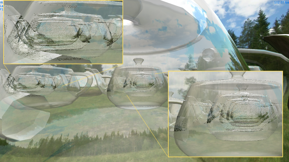
- Buffer size for storing list items. I used a buffer of 190Mb in size and could not reproduce the overflow on the stage of 36 dummies, but on polygonal models of complex shape this is possible and very likely. The buffer size can be increased, since graphical APIs do not explicitly limit the size of structured buffers and storage blocks. I reduced the buffer size 8 times to show what happens during an overflow.

- The complexity of the pixel (fragmentary) shader at the final stage of the algorithm. With an increase in MAX_FRAGMENTS and the inclusion of MSAA, the shader becomes increasingly heavy, which negatively affects the fillrate and can lead to serious “brakes”.
Performance
Performance measurements were taken on a computer with the following configuration: AMD Phenom II X4 970 3.79GHz, 16Gb RAM, AMD Radeon HD 7700 Series, running Windows 8.1.
Average frame time. Direct3D 11 / 1920x1080 / 400k-800k translucent fragments.
| MSAA / MAX_FRAGMENTS | eight | sixteen | 32 |
|---|---|---|---|
| 0 | 1.4835ms | 1.67446ms | 2.1275ms |
| 2x | 3.49895ms | 6.66149ms | 8.52533ms |
| 4x | 5.78841ms | 12.3358ms | 15.7224ms |
| 8x | 8.93051ms | 18.4825ms | 24.8538ms |
Average frame time. OpenGL 4.3 / 1920x1080 / 400k-800k translucent fragments.
| MSAA / MAX_FRAGMENTS | eight | sixteen | 32 |
|---|---|---|---|
| 0 | 3.25259ms | 4.10712ms | 16.8482ms |
| 2x | 5.06972ms | 7.16611ms | 33.6713ms |
| 4x | 7.22944ms | 12.3625ms | 62.5776ms |
| 8x | 11.2621ms | 19.0938ms | 115.026ms |
Average frame time. Direct3D 11 / 1920x1080 / ~ 5000k translucent fragments.
| MSAA / MAX_FRAGMENTS | eight | sixteen | 32 |
|---|---|---|---|
| 0 | 4.94471ms | 5.73306ms | 7.95545ms |
| 2x | 9.91625ms | 26.6783ms | 40.4808ms |
| 4x | 16.653ms | 50.7367ms | 77.038ms |
| 8x | 28.3847ms | 91.0873ms | 143.419ms |
Average frame time. OpenGL 4.3 / 1920x1080 / ~ 5000k translucent fragments.
| MSAA / MAX_FRAGMENTS | eight | sixteen | 32 |
|---|---|---|---|
| 0 | 16.2532ms | 22.0057ms | 139.678ms |
| 2x | 22.1646ms | 35.0568ms | 275.324ms |
| 4x | 30.4289ms | 56.7788ms | 536.241ms |
| 8x | 46.6934ms | 197.024ms | 1009.09ms |
It is easy to see that the implementation of the algorithm on Direct3D 11 is faster than on OpenGL 4.3. And on 5 million translucent fragments, the implementation on OpenGL “dies” with MSAA enabled and large values of MAX_FRAGMENTS . The results of the profiling showed that the algorithm spends most of the time on the final stage, i.e. on sorting and mixing colors of fragments. You should also take into account that my video card is far from the newest, and these figures show only the dynamics of the frame time change.
findings
The use of linked lists, probably, can be considered the most modern approach to the implementation of OIT. The algorithm works very quickly with reasonable settings for the quality and complexity of the semi-transparent part of the scene. 5 million visible translucent fragments in the frame is, in my opinion, enough even for the most modern game (about 2.5 times to cover the screen with a resolution of 1920x1080 with translucent fragments). MSAA, which can slow down the algorithm, can be discarded altogether if necessary or replaced by another anti-aliasing algorithm. The algorithm, of course, has flaws, but they are all clear, and can be fought with.
A little about terminology
It so happened that the terminology of computer graphics is almost entirely foreign. Below under the spoiler, I gave a number of terms that can be useful when reading the post.
Terms
Rendering is the process of drawing a three-dimensional scene on a two-dimensional medium (screen, texture).
Shader - a program for the graphics processor (GPU), which allows you to control one stage of the graphics pipeline. The vertex shader operates with vertices, the geometry with primitives (triangles, lines, etc.), the pixel (fragment) with the pixels formed at the output.
Rasterization is the process of forming a raster image from the vector representation of an object.
Depth Test - a test obtained when rendering fragments, which allows you to cut off fragments depending on the depth of the already drawn part of the scene. Usually, the depth of the fragment closest to the observer is recorded in the depth buffer.
MSAA (multi-sampling antialiasing) is one of the anti-aliasing algorithms implemented in both OpenGL and Direct3D.
MSAA texture - texture for rendering with anti-aliasing. It has a special format, type and set of operations in shaders.
Render target - where rendering. The term is commonly used when painting a scene into a texture.
MRT (multiple render targets) is a technology that allows rendering to multiple render targets at once.
Compute-shader - a program for the GPU, designed to solve a general-purpose task (perhaps not related to computer graphics).
Back buffer (back buffer) - in the multi-buffer rendering model, the buffer in which rendering is usually performed, and which changes places with the front buffer (front buffer) after the frame is finished drawing.
Framebuffer is a special object in OpenGL that allows you to combine multiple render targets and a depth buffer.
Fillrate - roughly the speed of filling the screen with pixels.
Source: https://habr.com/ru/post/224003/
All Articles