STM32 and LCD via I2C
For use in the future, it was necessary to connect using an I2C STM32 microcontroller with a 2004 screen. Having not found a similar solution on the network, I publish it here. This recipe is also suitable for screens 1602. Further under the cut. (Caution, pictures).
The toy ticket office, bought by the son, turned out to be defective, and worked through time. An idea appeared to remake its insides, and the moment of the choice of the microcontroller coincided with the publication of the RaJa article about STM32 [ 1 ]. Having estimated a bit and comparing the prices: STM32 + LCD2004 + I2C = ArduinoMega (the reason was that it was necessary to realize a keyboard, a speaker, a barcode input device and a screen, so each output of the microcontroller is on the account) I selected the first set.
Purchases were made, and it was time to wait. For the firmware I bought another USB-USART adapter.
What and where to buy.
- STM32F103C8T6
- 2004 LCD HD44780 . Turned out without Cyrillic. Pay attention to this feature when searching, if you need the Russian language on the screen.
- IIC / I2C / TWI / SP I Serial Interface Board Port Arduino 1602LCD Display Module For the description compatible with 2004. But I think any similar one will do.
- USB to UART TTL CP2012 for firmware and debugging. You can use other supported methods of firmware and debugging, but this option is the cheapest.
Tools for programming, firmware and debugging used by me:
- EmBlocks .
- Flash driver from original site: STM32 and STM8 Flash loader demonstrator .
- Terminal for reading signals from MK via USB2UART: Terminal v1.91b . But Putty (Connection-> Serial) will do.
After receiving the microcontroller I tried to play with the LEDs, it turned out. And then there were several hours of trying to link the screen with the MK. It’s boring to describe all this, I’ll try to remember the rake I ran into.
The first will describe the connection. Strange, describing the use of STM32 in few places draw diagrams, mostly code, guess what and how to connect.
Connect the image in the photo (by clicking - larger).
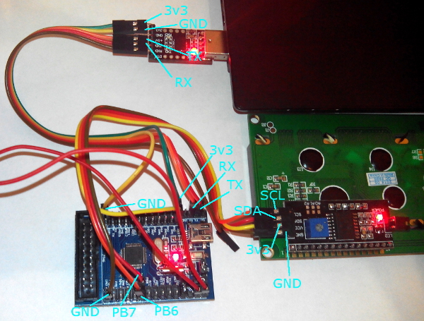
This connection is relevant for STM32F103C8. For other MK boards, check the connection pins of I2C1 by datasheet.
USART adapter to USB. This is understandable. Next - connect the USART to the STM32 derived from the miniUSB USART1 connector. TX to RX and respectively RX to TX. I have a 3v3 output on USART, I powered the MK from it. I connected the earth separately, for its convenient disconnection during the switching of the firmware modes and operation. I soldered the I2C to the screen (also on ebay there are screens with soldered I2C). Power for I2C and the screen is taken from 3v3 MK or 5V from USART. Below I wrote about the setting of contrast at different voltage supply. Next: SCL from I2C connects to PB6, SDA from I2C to PB7. Attracting SCL and SDA to power when using this device alone is not necessary.
')
The first rake was USART. I used it for debugging, in the code here, lines of work with it are commented out. But he did not solve the problem. It seems that there is no synchronization between the computer and the microcontroller before sending the first character. And if you use the code from the example [ 4 ] - then MK perfectly duplicates the resulting text, but it cannot write. I achieved the most appropriate debugging output for the lines by adding a delay (500) after each character.
Then he tried to implement the work with I2C. I took the code from the example [ 3 ], drew attention to the comments about the hanging of the MK, after analyzing the sources, I saw that, like the comment author, I need to shift the device address to the left:
//http://microtechnics.ru/stm32-ispolzovanie-i2c/#comment-8109 I2C_Send7bitAddress(I2Cx, slaveAddress<<1, transmissionDirection); Pasted the code and tried to run. The program hung at the time of waiting for the release of the bus:
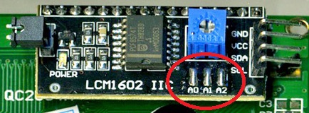
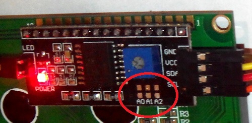
while(!I2C_CheckEvent(I2Cx, I2C_EVENT_MASTER_TRANSMITTER_MODE_SELECTED)); Here a rake in the device I2C address. Judging from the description of the seller, I had the address 0x20. Here I lost 15 minutes for nothing, but after reading the description of different models of I2C adapters, the link [ 6 ] to which I brought in my article [ 5 ] romanvl , I paid attention to the latest model and tried to change the address to 0x27. It all worked. The conclusion is this: if you have sealed on the adapter A0 A1 A2 - address 0x20, not sealed - 0x27.
Compare:
 |  |
Next - the screen. It turned out that it works perfectly from 3.3 volts, as well as the I2C adapter (in the adapter's datasheet, from 2.5 to 6 V). But first I checked it from 5B. And the contrast was twisted to the maximum. As a result, as a result of the launch of the program, the screen was completely full. I was upset and continued to pick the code. But after half an hour I woke up and the culprit ran up, I showed him the screen and accidentally saw at an angle from the side that something was written there. The reason for this is the wrong contrast adjustment. (Sorry if I described the obvious things here, maybe there are those who did not know this.)
 I can not see anything
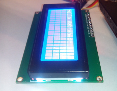 Same but angled
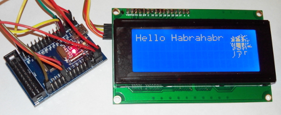
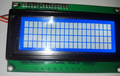
At 5V power supply, the contrast should be slightly reduced. And at 3.3V, put on a maximum, nothing is visible on the setting from 5V. The result is shown in the first picture in the post. My turned out to be without the Russian language, I saw it, scrolling through the characters. I tried to draw a blot, not knowing that the maximum you can define 8 of your characters, wrote for blot 12. I picked up similar ones from Chinese, it seemed to work out.

The code is presented on the Gihab, since to achieve the result I rewrote the library from Arduin: STM32_LCD_I2C .
Used materials:
- The reason for choosing a microcontroller: STM32 vs Arduino .
- From here, took the implementation of the Delay: STM32 I2C EEPROM 24CXX .
- Article about I2C STM32. Using I2C. microtechnics.ru/stm32-ispolzovanie-i2c . Immediately comment about the shift, without which I would probably just catch a rake as discussing.
- An example of working with the USART STM32. Usart Part 4 - Final .
- Reduce the number of wires in the Arduino - I2C LCD screen and RTC clock on two wires .
- LCD Displays (Blue and YELLOW) with I2C / TWI Interface .
- To understand the logic of the STM32 with external devices Quick Start Guide for working with STM32F10x peripherals .
Thanks for attention.
Source: https://habr.com/ru/post/223947/
All Articles