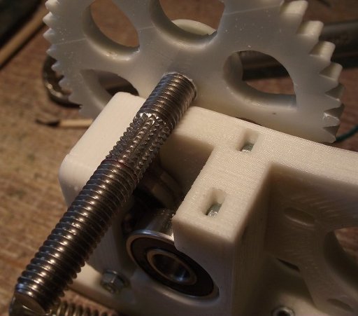
Rear printer: a view from the side of the head
General view - how to use them, native analogies. Modest reality. Only FDM, only home, alive - but from the inside and in detail. Hotand? In a section, with zones and the schedule of temperatures. The advantages and disadvantages, the properties of various solutions in the design of printheads. Features printing trim line, and experiments on obtaining tables of optimal settings for high-speed printing with nylon (nylon). Conclusions from them. On the organization of a good supply of nylon bar in the extruder. Everything is very exciting and dramatic.
About 3D printers now write a lot, they write with delight, a lot of models and technologies are described, as well as a lot of their skills. And now, I stand before you, a simple Russian peasant from Lithuania (C), with a 3D printer. Of course, I collected it myself. Not from a set - a year and a half ago there were few sets, and they were expensive. He planned everything and chose himself, focusing exclusively on the Internet. But I don’t want to talk about this, I want to talk about what happened next - after it was built, and I think the questions - Why is this? - What can he do? - Why buy it? - Many people ask themselves enthusiastic about technology.
Let's do it in order: first I built it. It was very interesting, in the sense that we had to constantly solve many technical issues, to find the causes of abnormal work - by calculation, often by indirect signs. A sort of technical puzzle game. It worked. Adjusting. I saw decent improvements. Made a few - with great pleasure. Then he developed a really convenient end sensor assembly for the printer. I even sold it once. Well, a set of sensors - you will not get rich on this, but then, what a pleasure I received from the sincere thanks of the buyer. Having fiddled with the printhead, I was convinced that, despite the good workmanship (brand MK IV), it also has a number of drawbacks. Yes, and she was only one - and buy more, expensive. I developed my own - you will laugh, something happened the first time, though not perfect. True, I did not blinded so much, but carefully studied what was available, read what was written, and only then did. Then he began to understand. To experiment There was a long break - disappointment and depression, but it is not related to printers, so the straw broke the back of an elephant. Now I have 4 heads, different diameters and the printer prints three times faster than it is considered normal and prints a layer of 150 microns. And prints not expensive imported filament, and cheap fishing line for trimmers. It turns out very, very durable, although not without tricks.
')
Let's talk further on the picture, and now:
So, - unequivocally, I got a convenient tool to make a plastic thing and a lot of positive emotions from technical creativity, improved skills in solving technical problems. Something like this. But do not forget - that they prepared from me a scientist and a chemical technologist. that is, I already had certain skills and mastered the methodology for finding the result, besides, still an amateur electronics engineer and computer scientist.
So the massiveness of this method of acquisition is questionable. Now I was reading another article on Habré about Them, and it reminded me of something ... well, I have old scientific and technical journals, I can remember. So, the 60s, 70s, 80s - it was written everywhere, more and more about the wonderful capabilities of computers, they became more and more, they became smaller, and in life they appeared little by little and from afar. That sheet with a payroll printed will bring - so after all also with errors! That train tickets in Moscow suddenly become unusually good to buy. Then the Household Computers appeared - BK-0010, Radio-86, Mikrosh - they were mainly used for their own technical creativity, it was really difficult and inconvenient to use them. They invented thousands of inconclusive and inconvenient applications, modernized them - I had Radio-86 with 56K (!) Of memory and 64K ROM (!) - it contained all the necessary programs, and at that time there were areas in the industry where without a computer no longer do. But how far they were from the people! (C). It was very similar to the current situation with 3D printing now: - a lot of “radio amateurs” are messing around with their little FDM printers (i.e., those that trickle something), and at this time, dentists and jewelers already their full use. Doctors, while in single copies - but used, where, because of the singularity of manufacturing, it would cost too much
It turns out that we have received another tool for the development of technical progress. For now, only this. But medicine - at a low start, is preparing to start using them actively, and this is understandable, medicine is a high-tech industry. Probably such places can be found quite a lot, but it would be dishonest to spread to Habr's readers only a bunch of bare reasoning - even on the topic, even - honest.
So, I want to tell you today about how one of the nodes of our home printer, the print head, works. You say - yes, what is there interesting! Plastic melts and flows out through the hole. If in three words - then so, but dozens of different models of heads, among which are completely unsuccessful, fall under this definition - people constantly clean them and curse dirty plastic. Oh, something I doubt this reason. There are heads that will work normally only with PLA-polylactide. He, although very environmentally friendly, is far from good everywhere. Rather, it is good because it is easy to make a cheap and stable printer for it. There are heads that, from work, quickly degrade, especially when working at high speeds and with not too fusible plastics. I will try to interestingly tell you, the general laws that I partly dug on the Internet, partly found myself - I had to do a lot of experiments and think a lot, it all happened to get confused, so if my opinion doesn’t coincide with yours, please do not beat me hard and consider what I am writing on the results of measurements of my system, so they may differ from the usual ones. I tried to check everything - to one degree or another. Think, try, maybe you will benefit from this information.
So, we’ll talk about the heads of the most common type of printers - printers, where a fishing line is turned into a printed object from one or another plastic. The fishing line is usually called filament or welding rod. Its material is usually ABS plastic, which means Acrylonitrile Butadiene Styrene is a fairly common plastic, PLA is also a polylactide, this name is correct in Russian, despite contradictory translation from English, this polymer is specially produced for 3D printers. However, theoretically almost any thermoplastic can be used. Practically used - nylon / nylon, polyvinyl alcohol - it can be dissolved in water and others. PLA plastic is loved by printer manufacturers, because it’s the least of problems with it; parts are obtained from it in almost any conditions. Rumors are about craftsmen printing on many other types of plastic.
So - the part of the printer, in which the melting of the filament occurs and the extrusion of the molten polymer stream is called the printhead. An important part of it is - an extruder, a node that captures the filament and pushes it into another, heated part of the head - hot end. Above it is in the picture. Let's see a picture of the hot-end in the section, and how temperature is distributed. Must thank colleagues from reprapology.info/archive/1422/rheology
- From this page, I learned the initial presentation of how melting and extrusion of the melt string from the head takes place. A little according to the scheme: the purple outside the head is a heating coil of nichrome or cantal, however in the heads a resistor is very often used as a heater - this is convenient in production, but reduces the reliability and uniformity of the heating field, since the resistor is located locally, therefore experiencing local overheating . However, there is no fundamental difference here - resistor or winding.
The red at the bottom of the head is the molten polymer zone, it is heterogeneous, as the polymer changes viscosity in the temperature range, and the orange zone is an area where the polymer has already reached plasticity, but is not yet fluid. This zone is very important - in it the plastic bar slightly expands, fits tightly against the walls and turns into a piston, which forces the melt through the outlet - the spinneret. Green - a zone where significant changes in plasticity have not yet occurred and the bar transmits pressure further without crushing. Different shading shows brass head and aluminum radiator. The PTFE guide tube is highlighted in white, because of the very small friction, the rod goes through it with minimal resistance. Gray — a stainless steel tube, a bearing head and a radiator, as well as a ring insert — it allows you to avoid mechanical stress on the Teflon tube in the hottest part. This is important - Teflon, in such conditions, is extremely mechanically unstable, so here it rests everywhere on steel - it can flow a little, but not soon, and this piece of Teflon tube is very easy to replace. The stainless steel tube is soldered to the brass head with silver solder - therefore there are no questions about thermal stability and strength. The ring (polished from the inside, to reduce friction!) Is simply inserted inside and pressed on top by a teflon tube. Please note - stainless steel must be of low thermal conductivity, for this it was chosen. Usually it is something like X18H10.
On the left, in the picture, you see a plot of temperature (approximate graph) along the axis of the tube. I cannot vouch for the accuracy of the scale, but the directions must be correct. The farther from the axis with the marking of zones, the higher the temperature. So we will describe by zones, starting with the last : Top - everything is cool.
Zone 6 - down the tube, the temperature increases evenly, as stainless steel has a low thermal conductivity, so the growth is quite fast. There is nothing special. The Teflon liner works in good conditions, the filament slowly warms up, the heat passing through the tube is dissipated by the upper radiator or holder.
Zone 5 Due to the fact that a small aluminum radiator is put on the tube, the temperature is almost constant and lies in the area not higher than the beginning of the softening of the plastic! The heat coming through the tube from zone 4 has time to be dissipated by the radiator - since the tube in zone 4 is a thermal barrier between the hot and cold parts.
Zone 4 - zone of active plastic softening, zone of thermal barrier. Its length is not great. Here plastic starts to warm up to form a plug, which serves as a piston pushing further and further. As shown by colleagues from reprapology.info if the cork-piston increases in length, this leads to stopping of the seal due to increased friction and painful problems with cleaning. In order to prevent this traffic jam from growing, it serves as a small radiator above, in the 5th zone. With the influx of heat through a thermal bridge made of stainless steel, it heats up, which means it begins to dissipate more heat. Thus, the process is self-stabilized and it is not at all difficult to get into the area of sustainable work. The heat dissipation by the radiator is large, and the thermal resistance of the bridge between the head and the radiator is large, therefore, the temperature rise with distance is high, which means that the optimum operating temperature is likely to fit on this segment to create a short, efficient piston. I did not even have to bore a stainless steel tube on the cone, as they had to, only polished slightly so that the Teflon liner would enter and exit well. Ring-liner polished well - from the inside, of course. The size of the lower radiator must be chosen so that its temperature is around 100-110 degrees, probably (this is the usual desktop temperature of the printer). This is done in order that, possibly, a large part of the thermal barrier zone is within the likely operating temperature range (probkoobrazovaniya!). So, to say briefly - for the stable operation of the head, the existence of a narrow zone with high thermal resistance (it is called a thermal barrier), in which the temperature would vary from working (for example 235), up to degrees 100, is approximately the temperature of the working table. I consider it inexpedient to cool the lower radiator below this temperature - it becomes more difficult to control the actual width of the probkoobrazovanie, and a lot of heat does not leak up through the stainless steel tube, and unnecessary energy losses. Yes! Important! Most heads are rated or work best, with continuous blowing with a small fan!
Zone 3 - I believe that it is in it that the final cork is formed, since there is a fairly strong heating here, this is the junction of the brass head and the steel tube. However, this heat somehow works to melt the filament.
Zone 2 - zone of active melting. When pulling the bar out of the working head (experiments), it was clear that the central part at a certain distance from the walls remained unmelted, that is, as the theory promises, melting occurs from the walls to the center of the bar. The zone of active heating is chosen long enough - a centimeter and a half. For a bar 3mm in diameter, it matters as it warms up more slowly, besides it is more convenient to wind the heater - there is where to turn.
Zone 1 The temperature is almost stable, gradually decreases towards the nozzle, it is good to place the temperature sensor here - it will show the temperature closest to the real temperature of the flowing melt. The total length of the brass part is the same as in the popular J-Head Mk 5-VB head.
It should be said that the absence of threaded connections at the junction of the heated part and the stainless steel tube - the thermal insulator - fully justifies itself, since the melt does not leak, and the thread with the plastic inside it is still difficult to unwind. It was not difficult to clean the hot end in case of a change of plastic and sometimes a solidification - I turned on the head to warm it up, waited, took out the filament by reversing the extruder, helping with my hand, squeezing liquid residues with a bamboo stick for a barbecue through the die plate - the diameter just fits. If it is very necessary, the melt can be taken out with a drill - just let it warm up with the plastic until the latter melts. Fluoroplast, too, in the hot, easily pulled out.
More about why all-metal hot-ends are becoming more and more popular. Yes, plastic gives significantly less friction than metal, especially if you take fluoroplastic. The only trouble is that the fluoroplastic (Teflon) under mechanical stress flows a little and bends, even at normal temperatures. This property of his led to the almost complete disappearance of structures, where Teflon played the role of a thermal barrier. It turned out badly. It remains to use it as an internal liner - where there is no place to flow to it, and a slight curvature of the channel does not lead to anything unpleasant, and the liner-tube, if needed, is easily removed and inserted new. I really didn’t have to change them yet. Take out the look - took out, and change - no. Here he is out of competition - very slippery. For thermal barrier is often used a different type of plastic (as in the photo above) - PEEK. It is much stronger, more heat-resistant and less slippery plastic. By the way - and dear, and scarce. The problem of the heads, where it is applied, is that the maximum working temperature there is about 250º. Above begins the risk of leakage through the threaded connection. However, there are usually enough such temperatures.
Now about the actual print - look at the drawing, at the end of the hotand there is such a patch around the die, it serves to smooth the protruding plastic trickle. When printing, the settings indicate the height of the layer - it is always less than the diameter of the die. For example, for 0.35 mm height can be both 0.2mm and 0.25mm, it depends on what we need. Thus, a trickle of plastic squeezing out in the form of a cylinder is smeared with a pin on the end of the head. With a small smearing, it turns out the worst connection between the layers, with a large, the line width increases, which means the print resolution decreases. On the extruded fishing line, even with its complete flatness, you can see bubbles - this is water, which could collect filament. ABS - captures moisture from the air weaker, capron - stronger. Moreover, printing with a wet nylon product turns noticeably softer, and even slightly lighter.
To be able to somehow assess the possibilities of the heads, I undertook a series of experiments. The main parameter I was interested in was speed. The program Pronterface, which controls printing, allows you to manually set all the printing parameters: the temperature of the head, the desktop, the feed speed of the extruder. The thread was squeezed into the air - the complete absence of other obstacles. It was necessary to evaluate the yield of plastic yarn by weight - due to the considerable non-uniformity of the yarn in length. This is due to the heterogeneity of the weight of the extruded thread acting on the thread at the exit of the nozzle, where it is most easily stretched.To avoid the influence of plastic leakage during idle time, before the measurement, a command was given to extrude a small piece, when the extruder stroke stopped, the extrusion very quickly broke off and the measuring section was started to extrude (a fairly large 10 cm filament). I also had to take measures against the phenomenon that had emerged, which appeared at very high feed rates — the hobbolt began to gnaw out part of the material due to slipping. This could distort up to 20% by weight. Therefore, after measurements at high speeds, 10 cm of the filament had to be simply drained at an average speed - or rather, I was not guided by speed - it may differ depending on the diameter of the nozzle, but was guided by the difference in the theoretical weight of the fed filament piece and actually extruded.
If the difference is 2 or more times, then the damage to the filament was great. I am talking about capron printing - ABS is not very interesting to me, there is nothing particularly exotic. Maybe later. If I have a small, precise lathe, it will be possible to try to make even faster printing, it will also be possible to use ABS.
But the other head is my work, let's call it BASS (Brass-Aluminum-Stainless Steel) materials.
So, taking all these measures to avoid mistakes, I began to press the plastic at different speeds, temperatures and heads, and that's what it turned out:
1. Head J -Head Mk 5-VB - native, USA, 0.4mm nozzle.
I led to the speed of the plastic filament at the nozzle exit — along its diameter.
Tables of experiments, I do not bring here, only conclusions. At a filament feed rate of 130–200 mm / min, the flow rate at the nozzle exit reached a maximum of 90 or 120 mm / sec. For nylon and ABS, respectively. A further increase in feed only reduced the extrusion. Slipping grew, chipping grew, speed did not grow. However, raising the temperature from 240º to 245 increased the flow rate by 25%.
It is clearly seen that insufficient heating of the plastic limits the performance.
I did not raise the temperature strongly for this model because it is close to the recommended limit.
2. Now the BASS-0,6 head - with a nozzle diameter of 0.6 mm, and at a temperature of 230º and at 240º,
when filing filament 264 mm / min limit was not reached. The cut speed was about 90 mm / s, which, due to the larger nozzle section, corresponds to a plastic flow rate of about 200 mm / s for the Mk 5 head! At the same time, the slip was only about 20%, that is, the speed could be increased! The melting efficiency turned out to be much better, probably because of the ring winding and the construction with a mini-radiator (shorter piston plug).
3. Now the BASS-0,6 head - diameter of 0,3 mm - the thinnest nozzle which could make.
It is clear that here the performance rests on the resistance to flow in a narrow nozzle.
For this, I did a series of experiments at temperatures of 240º, 250º and 260º. At each temperature increase, the maximum speed grew and rested against 95 - 110 - 140.
Then I did one more thing. Laid out on the desktop a strip of fine sanding paper (600), lowered the head to light pressure (in the cold, of course) and began to drive back and forth. Dropped three times at 0.1 mm, when it became easy to sand. This gave strict parallelism and reduced the narrow canal of the head by 0.3 mm. This action gave a speed of up to 170 mm / sec.
So, I got for myself a fairly accurate knowledge of maximum speeds at different temperatures, as well as a supply defect for these conditions. That is, how much less plastic will actually flow at such a speed. After that, he introduced a plastic feed correction of 1.25. He set the temperature to 260º and made all speeds in the settings close from 90 to 140 mm / s.
When a hot head is idle, without any pressure, quite a lot of melt can flow out of it, then at the start - squeezing command will begin only when the entire head void is filled. Sometimes because of this, I had problems sticking with the first layer - and this is critical! Now I, before starting the print, heat the table and the head to the working temperature, give a command to extrude a small amount of bar at medium speed, and then give the command to print the model. In this case, the thread starts to go immediately (more precisely, it is not interrupted) and this reason for poor adhesion is eliminated. Also, an important point - I took the working temperature of the printing table at 50º, I tried 100 and 110, the adhesion turned out worse, but the stickiness was better. On the cold, peeling off a nylon product from a kapton adhesive tape is very, very difficult. Kapton is a sticky filmit is glued onto glass and is a common and convenient substrate for printing - almost everything adheres well to it, and when necessary it is peeled off. So, now I am typing at 50º, and when the printing is over, I turn on the heating of the table for 100-110º, wait until it warms up and start to separate. Significantly better.
Another important thing is that with a solid product made of caprone with sizes larger than a few centimeters, its edges begin to bend upward, lag behind the substrate. A skirt (an existing function to counteract this phenomenon) helps a little. That is, it helps, but the plastic is so hard that if it does not separate the skirt from the Kapton, then it locally separates the Kapton from the glass substrate, it’s true, not so bad, but ... slots, bends. The decision has to be taken at the product design stage. ABS - does not have such a degree of deformation, although it exists, but less. And PLA, they say, does not have this property at all. ABS plastic, besides, perfectly breaks and cracks - it is rather fragile, but it also glues perfectly. A drop of acetone in the crack,after 10 minutes everything is fine again. Kapron, on the other hand, does not stick, although it doesn’t break, it’s quite flexible.
So - everything turned out. In some places, in the first layer, irregularities of spreading are visible - but the first layer ... Of course, for precision printing, both speed and temperature can and should be reduced, but the result that I got I really liked. Now the main thing is to learn how to design products. So that they are not distorted and will be very good. I did not succeed in raising the temperature to 270º due to the limitation in the printer firmware - it will be necessary to redo it. Attempting to apply 265º - did not give any increase - reached the minimum of viscosity? We must try to make the head with a different configuration of the internal part to further increase the speed.
Thus, I have got the tables, according to which I can say with what maximum speed (and accordingly, put it in the settings of the slicer), at a given temperature, the nylon will squeeze through a nozzle of a given diameter (0.3 and 0.6 tested well) . In doing so, I will know the magnitude of the extrusion multiplier correction. With a nozzle diameter of 0.4 mm, the maximum speed can reach 200mm / s. This is an estimate, you can check if there is a BASS workhead at 0.4mm, but you need to shorten the thermal barrier tube.
An important point in the print head is the extruder feed mechanism. The effectiveness of his work determines the quality of printing. The capron imposes a particularly high requirement on this mechanism, because the nylon is tough and slippery, in order to effectively push the hobbol rod, it must cut into it.This is obtained only if the clamping springs are strong enough and the notch of the hobbol should be very sharp. More precisely two points. A hobbolt is a bolt, with risks around the circumference that, when pressed against a filament, captures and pushes it in the right direction. If you use a filament of 1.75 mm in diameter, this is probably not so important, but if the diameter is 3 mm and you try to print with nylon / nylon, it is very likely that you will begin to slip the hobbol along a hard nylon. Therefore, I use a hobbolt with a "diamond" notch - I got her idea from Prof Braino's Prusa Build Log
He generally captures well, everything, only on soft ABS, with excessive clamping, can chop the bar - like a grater, if there is a traffic jam in the head - well, here it’s anyway, the problem must be solved, and it is not in the hobbolt.
For a filament diameter of 3 mm and a Wade extruder, the total force of the spring pressure should be around 7-20 kg. This, of course, may depend on the design of the extruder.
In conclusion, it should be added that the extremely important parameter of the print head is weight, and this is understandable, it is difficult to move a heavy head at high speed, these are unnecessary loads, chassis vibrations. One of the solutions -bowden extruder, is to separate the extruder with the motor and hotand, and unfortunately, has its drawbacks, so I did not use it, because I focused only on the most simple and reliable solutions.
At this stop the allowed speech (C). It would be necessary to build tables for heads of 0.4 and 0.5 mm, for ABS, it would be necessary to try to change the internal profile of the head - there are some clues that should help.
Source: https://habr.com/ru/post/223849/
All Articles