Weather station: from idea to implementation
I read many articles on the development of my device, and wanted to talk about my experience. It happened a few years ago, on the 4th year of uni. Now I would have done a lot differently, but at that time I was just starting to master electronics, this is my first device, so do not judge strictly.
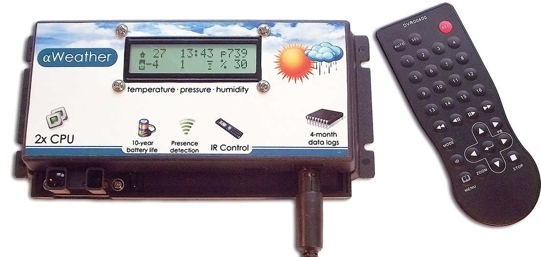
I always wanted something more than a normal thermometer outside the window or an LCD screen of a weather station with temperatures outside and in the room. Therefore, when I thought about what to do in order to start exploring the world of microcontrollers, the answer was found by itself — my own weather station. Naturally, with the display of degrees in the street and indoors, humidity and pressure. And with the backlight - I always liked the implementation of the weather forecast on Yandex - one glance at the background is enough to understand whether it will be warm or cold, and how much.
All further functionality was defined by a small brainstorming. The presence of illumination is definitely a plus, but how to be at night and in the evening? I decided to install an IR sensor that responds to the approximation. When approaching the device at a comfortable distance, the backlight turns on, at other times the screen does not light by default. The use of IR prompted the implementation of the instrument control also via the IR channel - via the console (at first there were concerns about mutual interference, but they were not confirmed). It is quite natural for such a device to have a clock.
As a basis for the system was chosen Arduino, which I was just beginning to learn. I myself consider the Arduino now (and even then) as a framework - first of all, a software one, which allows you to quickly build the necessary system by connecting, if necessary, library plug-ins. Yes, we can write in pure C / C ++, but in most ordinary tasks this gives only a slight performance increase, almost imperceptible against the background of simplicity and ease of loading sketches into Arduino, as well as an extensive collection of libraries for working with various hardware. (Of course, there are special tasks, but now it’s not about them).
In the hardware implementation, I prefer to use the blue Arduino board only at the prototyping stage on the prototype, and upon the completion of the development of devices, I usually design a single board with a microcontroller and everything else. So it was at that time.
')
I began the selection of components from the screen. Pretty quickly, there was a wonderful RGB-backlit screen at www.adafruit.com/products/398 , which made it possible to get almost any color. It is built on the popular HD44780 chip and is supported by a huge number of libraries, including LiquidCrystal in Arduino.
I also inquired about the prices for individual production of displays. The minimum price for 1 copy of a monochrome LCD (as in a typical weather station) at the prices of that time was about 1,000 euros, for a non-commercial project in a single copy, I found such a price tag impractical.
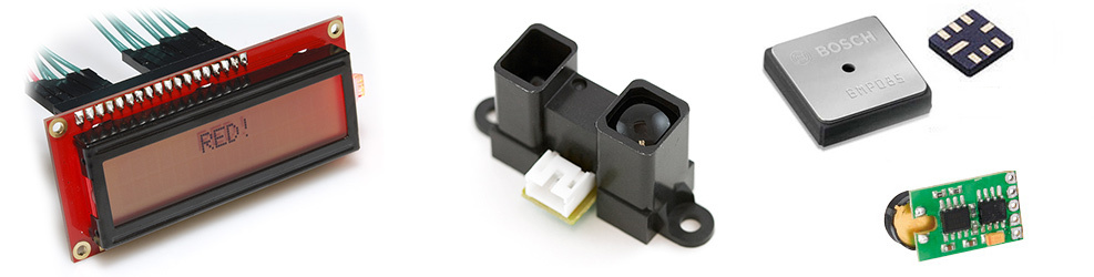
Sharp GP2Y0A02YK0F was chosen as an IR sensor. An important characteristic in my case was the object detection range, with this sensor it is equal to 1.5 m, while with many other sensors it does not exceed 30 cm. As the operation showed, for a small screen 16x2 and a half meters it is really the optimal distance.
The pressure sensor was selected Bosch BMP085 , working on I2C , humidity HH10D - with a frequency output. Looking ahead, I would say that now I would by no means use the latter, but I would prefer only I2C variants, for example, the HTU21D.
The DS18B20 was used as an external temperature sensor by everyone. Their great advantage is the ability to connect (and disconnect, if necessary) to one bus at once several sensors, without the need to change the program code. I did not communicate with the wireless transmission of temperature data in my first project, especially since I had the opportunity to lay wires without compromising aesthetics.
The IR receiver was taken as the most typical, type TSOP382. The remote control for the weather station was a remote control from some DVR. The buzzer (it's a squeaker) is the most common piezo emitter.
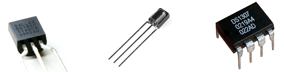
As a real-time clock, I chose the DS1307 , also running on I2C, and besides, I had a tiny flash memory chip 24AA256 of 64 KB with an I2C interface. I added it to the project out of pure curiosity - to try working with external memory, recording weather data in it. Power for the project - external, from the power supply. At the input is the LM7805 voltage converter / voltage regulator , the power node itself is very similar to that used in the Arduino (although it is not a clone).
I did the development with iterations, so it is much easier to debug and get acquainted with a new area for myself. At the very first stage, data were read from a DS18B20 thermometer and displayed on an LCD screen. On the following - the temperature values should have been converted into an RGB code for highlighting.
Here I was trapped by a color rendition feature. The color control of the screen is carried out using pulse-width modulation for each of the three backlight LEDs (using the standard library) with 256 steps - a seemingly quite ordinary 24-bit color. Unfortunately, the wavelengths for the R, G, and B colors of the monitor and the backlight LEDs are very different, and because of this, the usual colors, like # ffff00, look completely different on the background of my LCD screen (“go away”). So I had to write a program on C # with three sliders and a color picker, transmitting three color components to the Arduino serial port. Then I had to remember the basics of mathematics and create a function that converts the temperature in degrees Celsius into an RGB color scale. Naturally, I was no longer limited to the yellow-blue Yandex scale, and used other colors based on my associations.
The next step was to connect the IR rangefinder, temperature and humidity sensors. And, if there were no difficulties with the first two (except for the BMP085 soldering in the LCC8 package), then the humidity sensor caused a lot of problems.
The thing is that the final value of the relative humidity is calculated by the formula, one of whose arguments is the frequency of the meander at the output of the sensor. Frequency measurement is performed using a microcontroller hardware timer. In 328, unfortunately, there are only three such timers, and most of them are already involved in PWM to illuminate the display. (I don’t remember all the details now, I might have missed something).
There were several exits from this situation. If I developed the device today, I would definitely use only I2C sensors. Another option was to use a more powerful microcontroller. Then I chose the third option - to install a separate microcontroller for working with sound (beeper) and display illumination (let me remind you, this was primarily an educational project, and it was interesting for me to try to organize the interaction between the two MCs). It also turned the function of converting temperature to color, which made it easier for a couple of kilobytes of the firmware of the main MK (in Atmega328, the memory size of the program is only 32Kb, my firmware eventually came close to this limit). The interaction between the MK was still organized on I2C.
After that, a remote control, a clock, and a flash memory were added. The next step was to write a convenient menu, add software features (such as blocking the backlight in the current state, large numbers mode — like on a street clock, scrolling through all parameters), supporting several temperature sensors with their addition / deletion online (yes, I know that it is better not to do so). It is quite a common thing for a PC - and unusual at first for the device you assembled, when the project's functionality increases several times without changing the scheme ...
The console used some proprietary protocol. I did not engage in its reverse engineering, the hexadecimal representation of each button I received from the IRRemote library was quite enough for me. For flash memory, I chose to record weather data every 10 minutes, with a recording length of 16 bytes, this is enough for 4 months.
Code responsible for working with flash memory
LOGGER.h
LOGGER.cpp
#ifndef LOGGER_h #define LOGGER_h #include <WProgram.h> class LOGGER { public: LOGGER(int); void storeRecord16(byte* buffer); void getRecord16(unsigned int address, byte* buffer); int getAddress(); void setAddress(int); private: int _FlashI2CAddress; void _getAddress(); void _setAddress(); unsigned int _addr; }; #endif LOGGER.cpp
#include <WProgram.h> #include <Wire.h> #include "LOGGER.h" /* MEMORY MAP: 0000 - MSB of last written address 0001 - LSB of last written address ... 0040 - 7FFF - storage, */ LOGGER::LOGGER(int a) { _FlashI2CAddress = a; } void LOGGER::storeRecord16(byte* buffer) { byte c; //get address LOGGER::_getAddress(); //increase addr delay(5); _addr+=16; if(_addr>0x7FF0) _addr = 64; //store buffer Wire.beginTransmission(_FlashI2CAddress); Wire.send((byte) (_addr >> 8) & 0xFF); // MSB Wire.send((byte) (_addr & 0xFF) ); // LSB for ( c = 0; c < 16; c++) Wire.send(buffer[c]); Wire.endTransmission(); delay(20); //save new addr LOGGER::_setAddress(); } void LOGGER::getRecord16(unsigned int address, byte* buffer) { byte c; //set address Wire.beginTransmission(_FlashI2CAddress); Wire.send((byte) (address >> 8) & 0xFF); // MSB Wire.send((byte) (address & 0xFF) ); // LSB Wire.endTransmission(); Wire.requestFrom(_FlashI2CAddress,16); for (c = 0; c < 16; c++ ) if (Wire.available()) buffer[c] = Wire.receive(); } void LOGGER::_getAddress() { byte c; Wire.beginTransmission(_FlashI2CAddress); Wire.send(0); Wire.send(0); Wire.endTransmission(); Wire.requestFrom(_FlashI2CAddress,2); for (c = 0; c < 2; c++ ) if (Wire.available()) _addr = _addr * 256 + Wire.receive(); } void LOGGER::_setAddress() { Wire.beginTransmission(_FlashI2CAddress); Wire.send(0); // pointer Wire.send(0); // pointer Wire.send((byte) (_addr >> 8) & 0xFF); // MSB Wire.send((byte) (_addr & 0xFF) ); // LSB Wire.endTransmission(); } void LOGGER::setAddress(int addr) { _addr = addr; LOGGER::_setAddress(); } int LOGGER::getAddress() { LOGGER::_getAddress(); return _addr; } Uploading data is performed by a command from the weather station menu (something like the menu of old Nokia or Samsung, only without graphics) to the serial port.
After that, the meteorological station, which was completed functionally, stayed in the form of Arduino and prototyping boards for about a week. During this time of tests, the possibility of hanging up (caused by a leakage of the outdoor temperature sensor) was discovered. I redid the construction of the sensor (today I would only take the factory one, for example, such ), but I would also like to exclude the possibility of hangs in principle. In addition, I assumed that after 49 days of continuous operation, the millis () function will overflow, which, due to the features of the firmware algorithm, will also lead to a hang. Thing must be reliable! Therefore, the watchdog timer activation was the final touch in the system, as a result, any hangup is guaranteed not to last more than 2 seconds + 5 seconds to reboot (yes, in our digital age, even a weather station needs time to load.
So, the station is ready and working successfully. I think it is wrong to stop at this stage. The device must be comfortable and have a finished appearance, so that they can be used comfortably and shown to everyone, not just geek friends.
I started by going to the nearest radio shop and choosing a case. Of the 20-30 different options, I liked the one in the figure at the beginning of the article - because of the minimum required rework, because of the possibility to comfortably fix the rangefinder outside the case, so that it does not stick out strongly, because of good ventilation (and , more accurate temperature reading in the room). Today, I would probably order a print on a 3D printer and do something in this style:
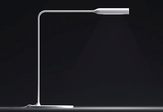
(It is difficult to find a similar picture, but in 3D modeling I am not a pro. The screen is located in the upper part, everything else is in the stand). And, of course, no wires - 433 MHz for sensors and Wi-Fi for communication with a PC.
After fitting and thinking how best to arrange everything, it was the turn of the development board. In my first project, I used the Eagle system. I drew the outline of the board, placed elements and connections on it (yes, I did this project in the "wrong" way - without a concept. More precisely, without a scheme in Eagle), the tracer easily parted everything. Took on the production ...
On Habré, they love the subject of manufacturing printed circuit boards, so here I’ll make a retreat. I am familiar with LUT, but I have no desire / ability to make boards, including contacting chemistry (ferric chloride is another thing). But at the university there is a small pilot production, where at very reasonable prices (~ $ 3 per sq. M. At that time) they can produce almost any bilateral PP. Technology - photoresist, holes - from 0.6mm, the minimum width of the track - like 0.2mm (just not larger, now I do not remember). Unfortunately, no soldering masks, metallization of vias for such a price can be expected, but this is all solved. In the end, for prototyping (and the boards are prepared for a day or two) and small-scale production, you can do without masks (IMHO; soldering by hand and large).
However, when I made an order, I did not think about the metallization of vias. Eagle safely used the legs of the elements as such, and it cost only 2-3 detached joints between the layers. The person at issue paid attention to this and kindly suggested the thinnest wire to create transitions in the holes for the elements (that is, first the wiring is soldered through the hole to the upper and lower contact area, after which the element leg itself is inserted into it). I tried to act this way, but the results and the amount of additional work did not inspire optimism. I had to redirect the fee, creating a zone of prohibition for the location of the via close to all PTH-elements. Here the automatic tracer refused to bring the work to the end, and I had to part the remaining chains manually (there was no longer any desire and time to change the design system). The vias themselves were eventually made using exactly the same technology, but I kept their number to a minimum. Soldering the newly ordered board was incomparably easier.
Next - the work of a drill, a knife and files, the body has acquired a window for the screen, mounting for the board. A couple of evenings - and the device in the case works successfully. And yet, something is missing ...
And there is not enough sticker on the front panel (especially after cutting through the window in it). Self-adhesive paper is a great thing for such tasks. What happened - on the title photo, do not judge strictly :) After that, the appearance of the device changed radically ...
This is how (in brief) my way of developing my first device looked like. Behind the scenes there are a lot of code, a lot of solutions to various small problems that arose along the way. The main thing that I gained for myself is the experience of development, full of bumps, an understanding of the principles of work, plus the meteorological station itself was a bonus. Unique and one of a kind.
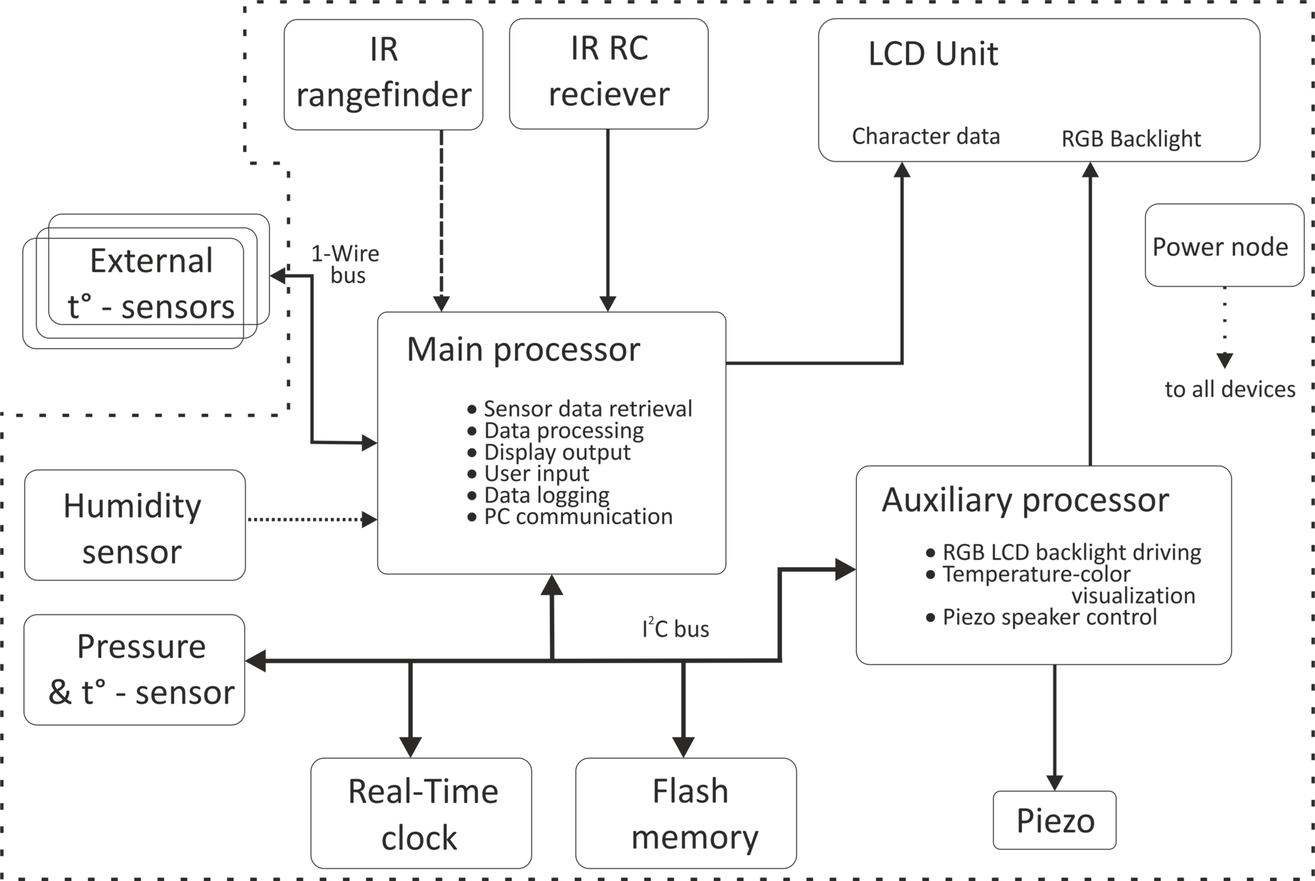
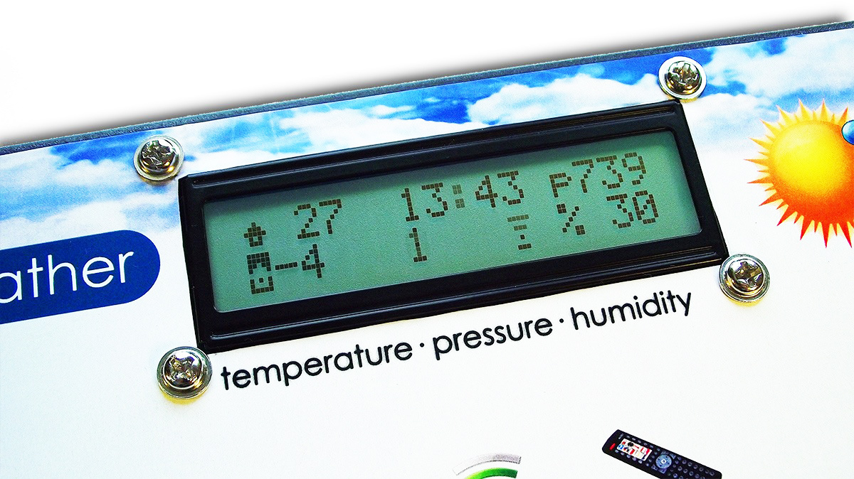
PS I know that many of the solutions are not optimal, but thanks to them (including) I now understand what is optimal and what is not :). Bonus attached functional diagram in English and a few photos, as well as render board.
Functional diagram:
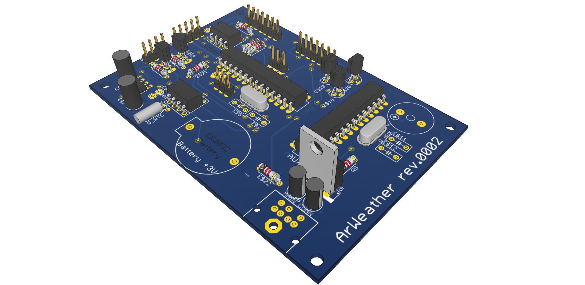
Render, the real fee without a solder mask. The lithium battery holder, piezo emitter, DIN connector (power, PC connection, sensors) and various small things are not shown. In addition, in a real device, microcontrollers are in sockets.
Large Digit mode, for better readability from a distance:

Source: https://habr.com/ru/post/223829/
All Articles