Graphene: the thinnest solid lubricant
Usually, when it comes to graphene, associations arise immediately with something microscopic, invisible to the naked eye, and, for the time being, not having any practical use outside the laboratories. This impression is enhanced after reading the news about the latest "applied" discoveries - whether it is "the thinnest motor" or "the thinnest and most flexible transistor." However, in addition to such applications, which are useful, but (so far) far from real life, there are areas where graphene can be used right now, moreover on a macroscopic scale. One of them is tribology.
First, a few words about tribology in general, and about the measurement of tribological properties, in particular. If officially, tribology is the science of friction and wear, the object of study of which is a pair of bodies in mechanical contact and moving relative to each other. In general, if you think about it, friction is probably the second most important physical phenomenon, after gravity. Try to sit on a chair without friction. No, you first get to it!
The two main tangible tribological parameters are the coefficients of friction and wear. With the coefficient of friction, everything is simple - this is the ratio of the friction force to the force with which the bodies are pressed together. For the first time I met this class size, probably in the seventh, on laboratories in physics. Remember, with the help of a spring dynamometer, one wooden bar was differently measured and this friction force was measured? Nobody mentioned about wear then for obvious reasons - it was somewhat problematic to measure it. The coefficient of wear is the ratio of the volume of a substance that irretrievably separated from the body in the process of friction, to the sliding distance. The simplest example is a brick being scratched with a nail. The ratio of the volume of the resulting crumb to the length of the scratch will be a coefficient of wear.
In modern laboratories, the principle of measuring tribological characteristics is almost the same as school laboratories. A simple device for measuring friction may look like this:
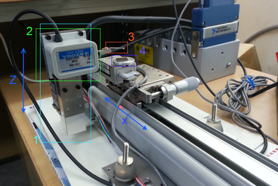
The main components are circled in colored frames: 1) A vertical actuator, used to move the measuring head up and down (to control normal force) 2) The measuring head (friction force sensor) is attached to it with a spring beam with a ball at the end (3). The test sample (4) is glued to the table, which is mounted on the sensor of normal force. All this goes back and forth along the X axis along the rail, which stands on the nightstand next to my desk))) In the upper right corner you can see the ADC module from National Instruments, which processes the signal from the sensors. Both actuators on stepper motors. Managed all samopisnym software under Windows.
')
The white ball at the end of the beam has a diameter of 1 mm, made of zirconium oxide. The sample, in this case, a silicon wafer 10 × 10 mm 2 . If you start to move the measuring head down, the ball will touch the surface of the sample, and upon further movement it will begin to press on it with a force that depends on the elasticity of the suspension and the degree of its deformation. Usually, 1 mm corresponds to 10 millinewtons. The exact value is measured by the bottom sensor.
If we set the reciprocating motion of the lower carriage, and wait, say, 10 minutes, we will see such a picture on the surface of our sample (on the left is a top view, on the right is a three-dimensional image of the central part; the track length is 2 mm):
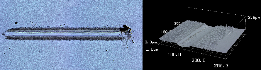
"Oh God, everything is gone!" Well, or "we wiped it!".
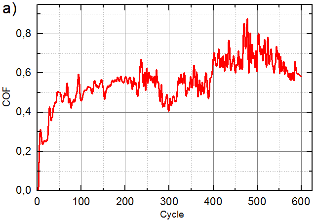
The dependence of the friction coefficient on the number of cycles will look like this:
Now back to graphene. If you apply graphene to silicon in any way, then the picture will change drastically!
With the same test parameters, we will not see any signs of wear on the surface of the sample, while the friction coefficient curve will look like this:
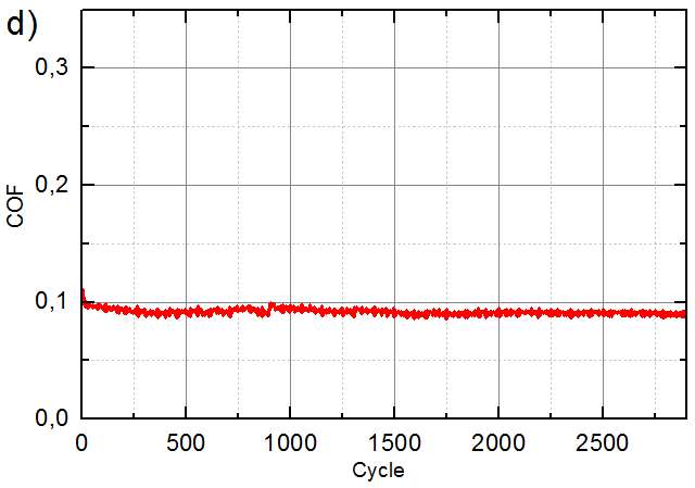
Those. Despite the fact that the graphene layer has a thickness less than a nanometer, and we climb a millimeter ball on it, it still does not break. Here is this strength!
“Stop!” The attentive reader will say. They promised the practical application! And where did you see the flat silicon bearing? Right, nowhere. But, fortunately, the light did not converge on silicon. Moreover, graphene on silicon is the result of its transfer from copper, on which it is grown, and this is more interesting.
There are two main ways to produce graphene. The first is mechanical exfoliation. It is not interesting to us, because it does not allow to get a large area coverage (more than a few millimeters). The second method is chemical vapor deposition (Chemical Vapor Deposition, CVD). In this method, the copper substrate is placed in a furnace and heated to a temperature of about 1000 degrees Celsius. Then the furnace is purged with pure hydrogen to reduce surface oxides, and is filled with methane. At high temperatures, methane decomposes, forming a carbon (graphene) film on the surface of copper, which acts as a catalyst. The number of graphene layers depends on the concentration of methane and the exposure time, which is usually 5–20 minutes. After that, the substrate is slowly cooled in an inert atmosphere. As a result, we get a piece of copper, uniformly coated with graphene. And how is he doing with friction? Yes, great!
This figure shows the friction coefficients for pure copper, as well as two pieces of copper coated with graphene of different thickness (exposure time in methane 5 and 20 minutes):
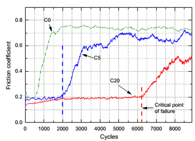
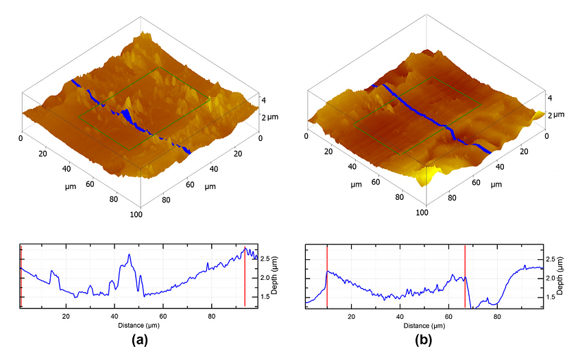
As you can see, pure copper surrenders immediately. But “thick” graphene (5 layers) increases the lifetime by ten times! At the same time, the copper surface is still deformed, and a “channel” is formed, which repeats the shape of a ball (on the left is pure copper, on the right is graphene):
But despite the deformation of the surface, graphene prevents the formation of scuffing, which keeps the coefficient of friction at a low level.
However, under pressure everything collapses, and graphene is no exception. In the previous figure, this moment is designated as “critical failure point”. After a certain number of cycles, the coefficient of friction begins to grow, although it remains lower than for pure copper. And this is caused not by the detachment of graphene and the exposure of the surface of copper, as one might think (“well, wiped through”). No, graphene remains in place, but changes its structure. The upper layers are destroyed, becoming amorphous, and amorphous carbon has a higher coefficient of friction. However, graphene continues to serve, protecting the surface of copper from oxidation.
It remains to make a copper liner for the bearing, cover it with graphene, and veil! Dry nano grease is ready. By the way, if you apply graphene to the balls themselves, the result will be phenomenal. But about it - next time.
References:
[1] MS Won, OV Penkov, DE Kim. Durability and degradation mechanism of graphene coatings deposited on substrates under dry contact. Carbon 54, pp. 472–481, 2013.
[2] OV Penkov, HJ Kim, HJ Kim, DE Kim. Tribology of Graphene: A Review. International Journal of Precision Engineering and Manufacturing 15, pp. 1–9, 2014.
______________________
First, a few words about tribology in general, and about the measurement of tribological properties, in particular. If officially, tribology is the science of friction and wear, the object of study of which is a pair of bodies in mechanical contact and moving relative to each other. In general, if you think about it, friction is probably the second most important physical phenomenon, after gravity. Try to sit on a chair without friction. No, you first get to it!
The two main tangible tribological parameters are the coefficients of friction and wear. With the coefficient of friction, everything is simple - this is the ratio of the friction force to the force with which the bodies are pressed together. For the first time I met this class size, probably in the seventh, on laboratories in physics. Remember, with the help of a spring dynamometer, one wooden bar was differently measured and this friction force was measured? Nobody mentioned about wear then for obvious reasons - it was somewhat problematic to measure it. The coefficient of wear is the ratio of the volume of a substance that irretrievably separated from the body in the process of friction, to the sliding distance. The simplest example is a brick being scratched with a nail. The ratio of the volume of the resulting crumb to the length of the scratch will be a coefficient of wear.
In modern laboratories, the principle of measuring tribological characteristics is almost the same as school laboratories. A simple device for measuring friction may look like this:
The main components are circled in colored frames: 1) A vertical actuator, used to move the measuring head up and down (to control normal force) 2) The measuring head (friction force sensor) is attached to it with a spring beam with a ball at the end (3). The test sample (4) is glued to the table, which is mounted on the sensor of normal force. All this goes back and forth along the X axis along the rail, which stands on the nightstand next to my desk))) In the upper right corner you can see the ADC module from National Instruments, which processes the signal from the sensors. Both actuators on stepper motors. Managed all samopisnym software under Windows.
')
The white ball at the end of the beam has a diameter of 1 mm, made of zirconium oxide. The sample, in this case, a silicon wafer 10 × 10 mm 2 . If you start to move the measuring head down, the ball will touch the surface of the sample, and upon further movement it will begin to press on it with a force that depends on the elasticity of the suspension and the degree of its deformation. Usually, 1 mm corresponds to 10 millinewtons. The exact value is measured by the bottom sensor.
If we set the reciprocating motion of the lower carriage, and wait, say, 10 minutes, we will see such a picture on the surface of our sample (on the left is a top view, on the right is a three-dimensional image of the central part; the track length is 2 mm):
"Oh God, everything is gone!" Well, or "we wiped it!".
The dependence of the friction coefficient on the number of cycles will look like this:
Now back to graphene. If you apply graphene to silicon in any way, then the picture will change drastically!
With the same test parameters, we will not see any signs of wear on the surface of the sample, while the friction coefficient curve will look like this:
Those. Despite the fact that the graphene layer has a thickness less than a nanometer, and we climb a millimeter ball on it, it still does not break. Here is this strength!
“Stop!” The attentive reader will say. They promised the practical application! And where did you see the flat silicon bearing? Right, nowhere. But, fortunately, the light did not converge on silicon. Moreover, graphene on silicon is the result of its transfer from copper, on which it is grown, and this is more interesting.
There are two main ways to produce graphene. The first is mechanical exfoliation. It is not interesting to us, because it does not allow to get a large area coverage (more than a few millimeters). The second method is chemical vapor deposition (Chemical Vapor Deposition, CVD). In this method, the copper substrate is placed in a furnace and heated to a temperature of about 1000 degrees Celsius. Then the furnace is purged with pure hydrogen to reduce surface oxides, and is filled with methane. At high temperatures, methane decomposes, forming a carbon (graphene) film on the surface of copper, which acts as a catalyst. The number of graphene layers depends on the concentration of methane and the exposure time, which is usually 5–20 minutes. After that, the substrate is slowly cooled in an inert atmosphere. As a result, we get a piece of copper, uniformly coated with graphene. And how is he doing with friction? Yes, great!
This figure shows the friction coefficients for pure copper, as well as two pieces of copper coated with graphene of different thickness (exposure time in methane 5 and 20 minutes):
As you can see, pure copper surrenders immediately. But “thick” graphene (5 layers) increases the lifetime by ten times! At the same time, the copper surface is still deformed, and a “channel” is formed, which repeats the shape of a ball (on the left is pure copper, on the right is graphene):
But despite the deformation of the surface, graphene prevents the formation of scuffing, which keeps the coefficient of friction at a low level.
However, under pressure everything collapses, and graphene is no exception. In the previous figure, this moment is designated as “critical failure point”. After a certain number of cycles, the coefficient of friction begins to grow, although it remains lower than for pure copper. And this is caused not by the detachment of graphene and the exposure of the surface of copper, as one might think (“well, wiped through”). No, graphene remains in place, but changes its structure. The upper layers are destroyed, becoming amorphous, and amorphous carbon has a higher coefficient of friction. However, graphene continues to serve, protecting the surface of copper from oxidation.
It remains to make a copper liner for the bearing, cover it with graphene, and veil! Dry nano grease is ready. By the way, if you apply graphene to the balls themselves, the result will be phenomenal. But about it - next time.
References:
[1] MS Won, OV Penkov, DE Kim. Durability and degradation mechanism of graphene coatings deposited on substrates under dry contact. Carbon 54, pp. 472–481, 2013.
[2] OV Penkov, HJ Kim, HJ Kim, DE Kim. Tribology of Graphene: A Review. International Journal of Precision Engineering and Manufacturing 15, pp. 1–9, 2014.
______________________
The text was prepared in the Blog Editor from © SoftCoder.ru
Source: https://habr.com/ru/post/223327/
All Articles