DIY: Universal Ambilight for home multimedia system - Atmosvet
Good day.
For my first article I chose one of my most successful handicrafts: HDMI-passthrough analogue of Philips Ambilight, then I will call this song “Atmosvet”.
On the Internet, it is not very difficult to find ready / open solutions and articles on how to make Ambilight for a monitor / TV, if you display a picture from a PC. But in my multimedia system, displaying pictures on a TV with a PC takes only 5% of the time of use, I play more games from game consoles, which means I had to invent something of my own.
')
Most devices use HDCP to play content even while playing.
It is necessary to provide centralized support for Atmosvet for all devices connected to the TV.
I will not tell you how I attached a 4.5m LED strip to a TV and what needs to be done with the Arduino, you can use this article as a base.
The only nuance:
I noticed that strange blinks were going on at the bottom of the screen, at first I sinned on the signal, rewrote the deflicker, changed the resizing of the picture and dug up a whole lot, it became better, but it didn’t help with the blink. Began to watch. It turned out that the flicker was only at the end of the tape, and then with bright scenes. Taking a multimeter, I measured the voltage at the beginning, middle and end of the tape and guessed the cause of the flicker: at the beginning of the tape was 4.9V (yes, the Chinese PD gives voltage with a deviation, this is not significant), in the middle of 4.5 at the end 4.22 - The voltage drop is too significant I just had to solve the problem - by the middle of the tape I had power from the power supply unit, the wire was let out behind the TV. It helped instantly, any flicker stopped altogether.
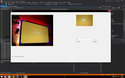
The first test version for running in the idea and its visualization was selected through a webcam image capture) it looked something like this:
Low color rendering and high latency showed that this implementation cannot be used in any way.
In the process of exploring possible options, the following scheme was chosen as the most reliable and budgetary one:
Initially it looks wild and like crutches, but:
Why I did not use the board for HDMI capture? It's simple: the cheapest option and affordable is the Blackmagic Intensity Shuttle, but it cannot work with a 1080p / 60fps signal, only with 1080p / 30fps - which is not acceptable, because I did not want to lower the frame rate so that I could capture the picture. + This case cost around 10 thousand. rubles. - which is not cheap with an unknown result.
The HDMI to S-video conversion loss is insignificant for capturing color in the resolution of 46x26 LED backlighting.
Initially, I tried to use EasyCap for capturing S-video (it has a lot of Chinese variations), but the point is that the chip used there is extremely poor, and you cannot work with it using openCV.
The only minus is that the S-Video output signal contained black bars at the edges that cut off the real content (about 2-5%), I cut the output image from the capture card to remove these bands, the very loss of the image in those areas did not affect the result in practice.
For me it was the most interesting part, because with glands, I don’t really like poking around.
To capture a picture, I used openCV and in particular its .NET wrapper emgu CV .
I also decided to apply several different post-processing techniques for the image and its preparation, before giving the list of colors to the controller.
Everything is simple:
Crop 8 pixels on the top, 8 on the right and 18 on the bottom. (There is no band on the left)
Also nothing complicated, we do it with openCV:
frame.Resize (LedWidth - 2 * LedSideOverEdge,
LedHeight - LedBottomOverEdge - LedTopOverEdge,
INTER.CV_INTER_LINEAR);
The attentive reader will notice an abundance of variables. The fact is that my TV frame is quite large, taking up 1 LED on the sides, 1 on top and 3 on the bottom, so the resize is placed on the LEDs that are directly opposite the display, and we already add corners later. When resizing, we just get the average colors that the pixels of the LEDs should have.
Well, here, too, everything is simple, stupidly we pass on each side and successively fill an array of 136 values with the color of the LEDs. So it turned out that at the moment all other operations are easier to perform with an array of LEDs than with a frame that is harder to process. Also for the future, I added the “depth” parameter of capture (the number of pixels from the border of the screen, for averaging the color of the LED), but in the final setup, it turned out better without it.
The walls behind the TV in my bar, yellow timber, so you need to compensate for the yellowness.
var blue = 255.0f / (255.0f + blueLevelFloat) * pixelBuffer [k];
var green = 255.0f / (255.0f + greenLevelFloat) * pixelBuffer [k + 1];
var red = 255.0f / (255.0f + redLevelFloat) * pixelBuffer [k + 2];
In general, I initially from the source of some open source editor took the color balance, but he did not change white (white remained white), I changed the formulas a little, sealed up, and got straight what I needed: if the level of the color component is negative (I will understand how this color is not enough), then we add its intensity and vice versa. For my walls it turned out: RGB (-30,5,85).
In color correction, I also align the black level (black comes somewhere around 13,13,13 in RGB), just subtracting 13 from each component.
In the final setup, I do not use desaturation, but at some point I may need it, in fact it makes the colors more “pastel”, like Phillips’s ambilight. I will not give the code, we simply convert from RGB -> HSL, reduce the Saturation component (saturation) and go back to RGB.
So it turns out that the input image is “trembling” - this is a consequence of converting to an analog signal, as I suppose. At first I tried to solve it in my own way, then I spied on the source of the Defliker filter used in VirtualDub, rewrote it in C # (it was in C ++), I realized that it does not work, because it is such that it fights with flicker between frames. in the end, I combined my decision and this deflicker received something strange, but it worked better than expected. The initial deflicker worked only with the intensity of the entire frame, I need for each LED separately. The initial deflicker compared the intensity change as a sum, I like the comparison of the length of the color vector more. The initial deflicker compared the delta intensity change compared with the previous frame, it does not fit, and I redid the average intensity value within the previous frame window. And there are many other little things, as a result of which little was left of the initial deflicker.
The basic idea: based on the average intensity of previous frames, to perform the modification of the current frame, if its intensity is not above a certain threshold (I have this threshold in the final setup 25), if the threshold is over, then the window is reset without modification.
A slightly modified (for out-of-context readability) code of my deflicker:
Let _leds be an array of Color LEDs, _ledsOld are frame values before conversion, LedLumWindow is the window width of previous frames, to estimate the average intensity change, in the final setup window I had 100, which is about 30 seconds / s for 3 seconds. _lumData is an array of intensity values of previous frames.
In the end, this mechanism gave more pleasant unexpected effects on the picture, it is difficult to describe how it is perceived visually, but it makes it darker where necessary and brighter where necessary, like a dynamic contrast. The purpose of the deflicker was a broad result, not only eliminating flicker, but also a general balancing of the displayed color, both in terms of the components and the time within the window.
In general, in the final setup, I did not really like the smoothing, and I turned it off, but in some cases it may be useful. Here we simply average the color of each LED over its neighbors.
I deliberately divided the process of processing frames and sending packets to the controller: the packets are sent once a certain interval (I have 40ms) so that Arduino sings to process the previous one, because more than 30ms she drowns, so it turns out that we are not directly dependent on the frame rate capture and do not interfere with that process (and after all sending a package also spends time).
You can’t just take and send a huge Arduino package on the TV series, because it will go beyond the HardwareSerial default buffer and you will lose its end.
This is solved quite simply: setting the size of the HardwareSerial buffer of sufficient size to fit the entire packet with an array of colors, for me it is 410.
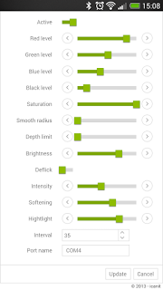
The software itself was implemented as a win service, in order to configure all the parameters + enable / disable I did a Web UI that communicated with the service through the WebService on the service. The final interface on the mobile screen looks like this:
Now I plan to screw the voice control through Kinect for Windows connected to the HTCP.
As a result, the result met all expectations, and now playing games on consoles, I get even more immersion in the atmosphere of the game.
As a general result of the work, I recorded a video with the work of the atmosphere according to my scheme:
Test sample 1: Pacific Rim, a battle scene in Shanghai, this film is well suited for testing and demonstration, many vivid scenes and flashes, lightning strikes, etc .:
Test sample 2: A clip from MLP, merged from YouTube, is very well suited to test scenes with bright colors (I liked the stripes), as well as quickly changing scenes (at the end of the video you can see the effects of the delay, visible only on video, while It’s not noticeable to the real view, I tried to measure the video delay - it turned out 10-20ms):
And lastly, it is worth noting about the resource consumption from the HTPC:
HTPC is ASRock Vision 3D on i3, the atmosphere service is 5-10% CPU and 32MB RAM.
Thank you for your attention, I really hope that my article will help someone.
For my first article I chose one of my most successful handicrafts: HDMI-passthrough analogue of Philips Ambilight, then I will call this song “Atmosvet”.
Introduction
On the Internet, it is not very difficult to find ready / open solutions and articles on how to make Ambilight for a monitor / TV, if you display a picture from a PC. But in my multimedia system, displaying pictures on a TV with a PC takes only 5% of the time of use, I play more games from game consoles, which means I had to invent something of my own.
')
Initial data:
- 60 "Plasma TV
- HTPC based on Asrock Vision 3D 137B
- Xbox 360
- PS3
- PS4
- WiiU
Most devices use HDCP to play content even while playing.
Demand:
It is necessary to provide centralized support for Atmosvet for all devices connected to the TV.
Implementation
I will not tell you how I attached a 4.5m LED strip to a TV and what needs to be done with the Arduino, you can use this article as a base.
The only nuance:
I noticed that strange blinks were going on at the bottom of the screen, at first I sinned on the signal, rewrote the deflicker, changed the resizing of the picture and dug up a whole lot, it became better, but it didn’t help with the blink. Began to watch. It turned out that the flicker was only at the end of the tape, and then with bright scenes. Taking a multimeter, I measured the voltage at the beginning, middle and end of the tape and guessed the cause of the flicker: at the beginning of the tape was 4.9V (yes, the Chinese PD gives voltage with a deviation, this is not significant), in the middle of 4.5 at the end 4.22 - The voltage drop is too significant I just had to solve the problem - by the middle of the tape I had power from the power supply unit, the wire was let out behind the TV. It helped instantly, any flicker stopped altogether.
Capture image webcam
The first test version for running in the idea and its visualization was selected through a webcam image capture) it looked something like this:
Low color rendering and high latency showed that this implementation cannot be used in any way.
Capturing pictures via HDMI
In the process of exploring possible options, the following scheme was chosen as the most reliable and budgetary one:
- The signal from all devices is fed to the 5in-1out HDMI switch that supports HDCP
- The output signal is sent to the 1in-2out HDMI splitter , which not only supports HDCP, so also turn it off at the output (thank the Chinese).
- One of the output signals goes to the TV.
- Another output goes to HDMI to AV Converter
- S-Video signal goes to the capture box from ICONBIT
- The capture box connects to the ever-running HTCP via USB, which is connected to the Arduino controller tape on the TV.
Initially it looks wild and like crutches, but:
- It works.
- Sumno the whole thing, ordering from China, I cost thousands of 3-4 thousand rubles.
Why I did not use the board for HDMI capture? It's simple: the cheapest option and affordable is the Blackmagic Intensity Shuttle, but it cannot work with a 1080p / 60fps signal, only with 1080p / 30fps - which is not acceptable, because I did not want to lower the frame rate so that I could capture the picture. + This case cost around 10 thousand. rubles. - which is not cheap with an unknown result.
The HDMI to S-video conversion loss is insignificant for capturing color in the resolution of 46x26 LED backlighting.
Initially, I tried to use EasyCap for capturing S-video (it has a lot of Chinese variations), but the point is that the chip used there is extremely poor, and you cannot work with it using openCV.
The only minus is that the S-Video output signal contained black bars at the edges that cut off the real content (about 2-5%), I cut the output image from the capture card to remove these bands, the very loss of the image in those areas did not affect the result in practice.
Soft
For me it was the most interesting part, because with glands, I don’t really like poking around.
To capture a picture, I used openCV and in particular its .NET wrapper emgu CV .
I also decided to apply several different post-processing techniques for the image and its preparation, before giving the list of colors to the controller.
Frame processing
1. Getting captured frame
2. Crop frame, to exclude black bars
Everything is simple:
frame.ROI = new Rectangle(8, 8, frame.Width - 8, frame.Height - 18 - 8); Crop 8 pixels on the top, 8 on the right and 18 on the bottom. (There is no band on the left)
3. Resize the frame in the backlight resolution, there’s no need for us to carry a healthy picture with us
Also nothing complicated, we do it with openCV:
frame.Resize (LedWidth - 2 * LedSideOverEdge,
LedHeight - LedBottomOverEdge - LedTopOverEdge,
INTER.CV_INTER_LINEAR);
The attentive reader will notice an abundance of variables. The fact is that my TV frame is quite large, taking up 1 LED on the sides, 1 on top and 3 on the bottom, so the resize is placed on the LEDs that are directly opposite the display, and we already add corners later. When resizing, we just get the average colors that the pixels of the LEDs should have.
4. We carry out mapping of light-emitting diodes from a rendered frame
Well, here, too, everything is simple, stupidly we pass on each side and successively fill an array of 136 values with the color of the LEDs. So it turned out that at the moment all other operations are easier to perform with an array of LEDs than with a frame that is harder to process. Also for the future, I added the “depth” parameter of capture (the number of pixels from the border of the screen, for averaging the color of the LED), but in the final setup, it turned out better without it.
5. Perform color correction (white balance / color balance)
The walls behind the TV in my bar, yellow timber, so you need to compensate for the yellowness.
var blue = 255.0f / (255.0f + blueLevelFloat) * pixelBuffer [k];
var green = 255.0f / (255.0f + greenLevelFloat) * pixelBuffer [k + 1];
var red = 255.0f / (255.0f + redLevelFloat) * pixelBuffer [k + 2];
In general, I initially from the source of some open source editor took the color balance, but he did not change white (white remained white), I changed the formulas a little, sealed up, and got straight what I needed: if the level of the color component is negative (I will understand how this color is not enough), then we add its intensity and vice versa. For my walls it turned out: RGB (-30,5,85).
In color correction, I also align the black level (black comes somewhere around 13,13,13 in RGB), just subtracting 13 from each component.
6. Perform desaturation (reducing image saturation)
In the final setup, I do not use desaturation, but at some point I may need it, in fact it makes the colors more “pastel”, like Phillips’s ambilight. I will not give the code, we simply convert from RGB -> HSL, reduce the Saturation component (saturation) and go back to RGB.
7. Deflicker
So it turns out that the input image is “trembling” - this is a consequence of converting to an analog signal, as I suppose. At first I tried to solve it in my own way, then I spied on the source of the Defliker filter used in VirtualDub, rewrote it in C # (it was in C ++), I realized that it does not work, because it is such that it fights with flicker between frames. in the end, I combined my decision and this deflicker received something strange, but it worked better than expected. The initial deflicker worked only with the intensity of the entire frame, I need for each LED separately. The initial deflicker compared the intensity change as a sum, I like the comparison of the length of the color vector more. The initial deflicker compared the delta intensity change compared with the previous frame, it does not fit, and I redid the average intensity value within the previous frame window. And there are many other little things, as a result of which little was left of the initial deflicker.
The basic idea: based on the average intensity of previous frames, to perform the modification of the current frame, if its intensity is not above a certain threshold (I have this threshold in the final setup 25), if the threshold is over, then the window is reset without modification.
A slightly modified (for out-of-context readability) code of my deflicker:
Array.Copy(_leds, _ledsOld, _leds.Length); for (var i = 0; i < _leds.Length; i++) { double lumSum = 0; // Calculate the luminance of the current led. lumSum += _leds[i].R*_leds[i].R; lumSum += _leds[i].G*_leds[i].G; lumSum += _leds[i].B*_leds[i].B; lumSum = Math.Sqrt(lumSum); // Do led processing var avgLum = 0.0; for (var j = 0; j < LedLumWindow; j++) { avgLum += _lumData[j, i]; } var avg = avgLum/LedLumWindow; var ledChange = false; if (_strengthcutoff < 256 && _lumData[0, i] != 256 && Math.Abs((int) lumSum - avg) >= _strengthcutoff) { _lumData[0, i] = 256; ledChange = true; } // Calculate the adjustment factor for the current led. var scale = 1.0; int r, g, b; if (ledChange) { for (var j = 0; j < LedLumWindow; j++) { _lumData[j, i] = (int) lumSum; } } else { for (var j = 0; j < LedLumWindow - 1; j++) { _lumData[j, i] = _lumData[j + 1, i]; } _lumData[LedLumWindow - 1, i] = (int) lumSum; if (lumSum > 0) { scale = 1.0f/((avg+lumSum)/2); var filt = 0.0f; for (var j = 0; j < LedLumWindow; j++) { filt += (float) _lumData[j, i]/LedLumWindow; } scale *= filt; } // Adjust the current Led. r = _leds[i].R; g = _leds[i].G; b = _leds[i].B; // save source values var sr = r; var sg = g; var sb = b; var max = r; if (g > max) max = g; if (b > max) max = b; double s; if (scale*max > 255) s = 255.0/max; else s = scale; r = (int) (s*r); g = (int) (s*g); b = (int) (s*b); // keep highlight double k; if (sr > _lv) { k = (sr - _lv)/(double) (255 - _lv); r = (int) ((k*sr) + ((1.0 - k)*r)); } if (sg > _lv) { k = (sg - _lv)/(double) (255 - _lv); g = (int) ((k*sg) + ((1.0 - k)*g)); } if (sb > _lv) { k = (sb - _lv)/(double) (255 - _lv); b = (int) ((k*sb) + ((1.0 - k)*b)); } _leds[i] = Color.FromArgb(r, g, b); } /* Temporal softening phase. */ if (ledChange || _softening == 0) continue; var diffR = Math.Abs(_leds[i].R - _ledsOld[i].R); var diffG = Math.Abs(_leds[i].G - _ledsOld[i].G); var diffB = Math.Abs(_leds[i].B - _ledsOld[i].B); r = _leds[i].R; g = _leds[i].G; b = _leds[i].B; int sum; if (diffR < _softening) { if (diffR > (_softening >> 1)) { sum = _leds[i].R + _leds[i].R + _ledsOld[i].R; r = sum/3; } } if (diffG < _softening) { if (diffG > (_softening >> 1)) { sum = _leds[i].G + _leds[i].G + _ledsOld[i].G; g = sum/3; } } if (diffB < _softening) { if (diffB > (_softening >> 1)) { sum = _leds[i].B + _leds[i].B + _ledsOld[i].B; b = sum/3; } } _leds[i] = Color.FromArgb(r, g, b); } Let _leds be an array of Color LEDs, _ledsOld are frame values before conversion, LedLumWindow is the window width of previous frames, to estimate the average intensity change, in the final setup window I had 100, which is about 30 seconds / s for 3 seconds. _lumData is an array of intensity values of previous frames.
In the end, this mechanism gave more pleasant unexpected effects on the picture, it is difficult to describe how it is perceived visually, but it makes it darker where necessary and brighter where necessary, like a dynamic contrast. The purpose of the deflicker was a broad result, not only eliminating flicker, but also a general balancing of the displayed color, both in terms of the components and the time within the window.
8. Smoothing LEDs on neighbors.
In general, in the final setup, I did not really like the smoothing, and I turned it off, but in some cases it may be useful. Here we simply average the color of each LED over its neighbors.
var smothDiameter = 2*_smoothRadius + 1; Array.Copy(_leds, _ledsOld, _leds.Length); for (var i = 0; i < _ledsOld.Length; i++) { var r = 0; var g = 0; var b = 0; for (var rad = -_smoothRadius; rad <= _smoothRadius; rad++) { var pos = i + rad; if (pos < 0) { pos = _ledsOld.Length + pos; } else if (pos > _ledsOld.Length - 1) { pos = pos - _ledsOld.Length; } r += _ledsOld[pos].R; g += _ledsOld[pos].G; b += _ledsOld[pos].B; } _leds[i] = Color.FromArgb(r/smothDiameter, g/smothDiameter, b/smothDiameter); } 9. Save the current state, so that the thread of sending the packages is grabbed and sent to the backlight controller.
I deliberately divided the process of processing frames and sending packets to the controller: the packets are sent once a certain interval (I have 40ms) so that Arduino sings to process the previous one, because more than 30ms she drowns, so it turns out that we are not directly dependent on the frame rate capture and do not interfere with that process (and after all sending a package also spends time).
A little about Arduino
You can’t just take and send a huge Arduino package on the TV series, because it will go beyond the HardwareSerial default buffer and you will lose its end.
This is solved quite simply: setting the size of the HardwareSerial buffer of sufficient size to fit the entire packet with an array of colors, for me it is 410.
Ui
The software itself was implemented as a win service, in order to configure all the parameters + enable / disable I did a Web UI that communicated with the service through the WebService on the service. The final interface on the mobile screen looks like this:
Now I plan to screw the voice control through Kinect for Windows connected to the HTCP.
Result
As a result, the result met all expectations, and now playing games on consoles, I get even more immersion in the atmosphere of the game.
As a general result of the work, I recorded a video with the work of the atmosphere according to my scheme:
Test sample 1: Pacific Rim, a battle scene in Shanghai, this film is well suited for testing and demonstration, many vivid scenes and flashes, lightning strikes, etc .:
Test sample 2: A clip from MLP, merged from YouTube, is very well suited to test scenes with bright colors (I liked the stripes), as well as quickly changing scenes (at the end of the video you can see the effects of the delay, visible only on video, while It’s not noticeable to the real view, I tried to measure the video delay - it turned out 10-20ms):
And lastly, it is worth noting about the resource consumption from the HTPC:
HTPC is ASRock Vision 3D on i3, the atmosphere service is 5-10% CPU and 32MB RAM.
Thank you for your attention, I really hope that my article will help someone.
Source: https://habr.com/ru/post/222925/
All Articles