Model-oriented design on the knee, system identification in MATLAB / Simulink
Hi, Habr!
Today I want to show a simple example of system identification based on observations and experimental data. This is the first and extremely important step in developing a device management system that is analytically impossible to describe, or too difficult,
I ask those interested under the cat.
Hardware and software available
WatchdogWatchduck:
Performs the same function as the Watchdog timer, but with reference to the engineer - it helps to get out of the hang.
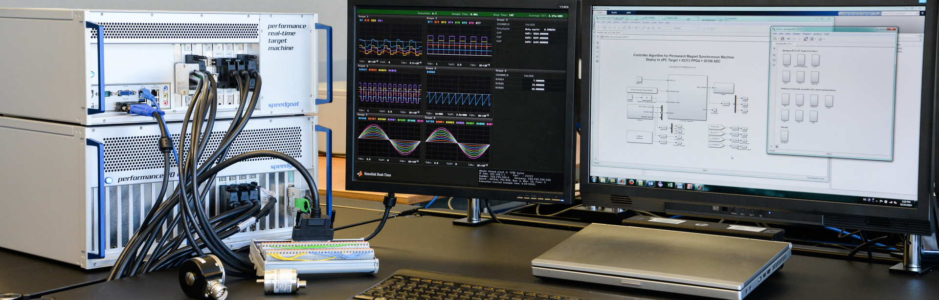
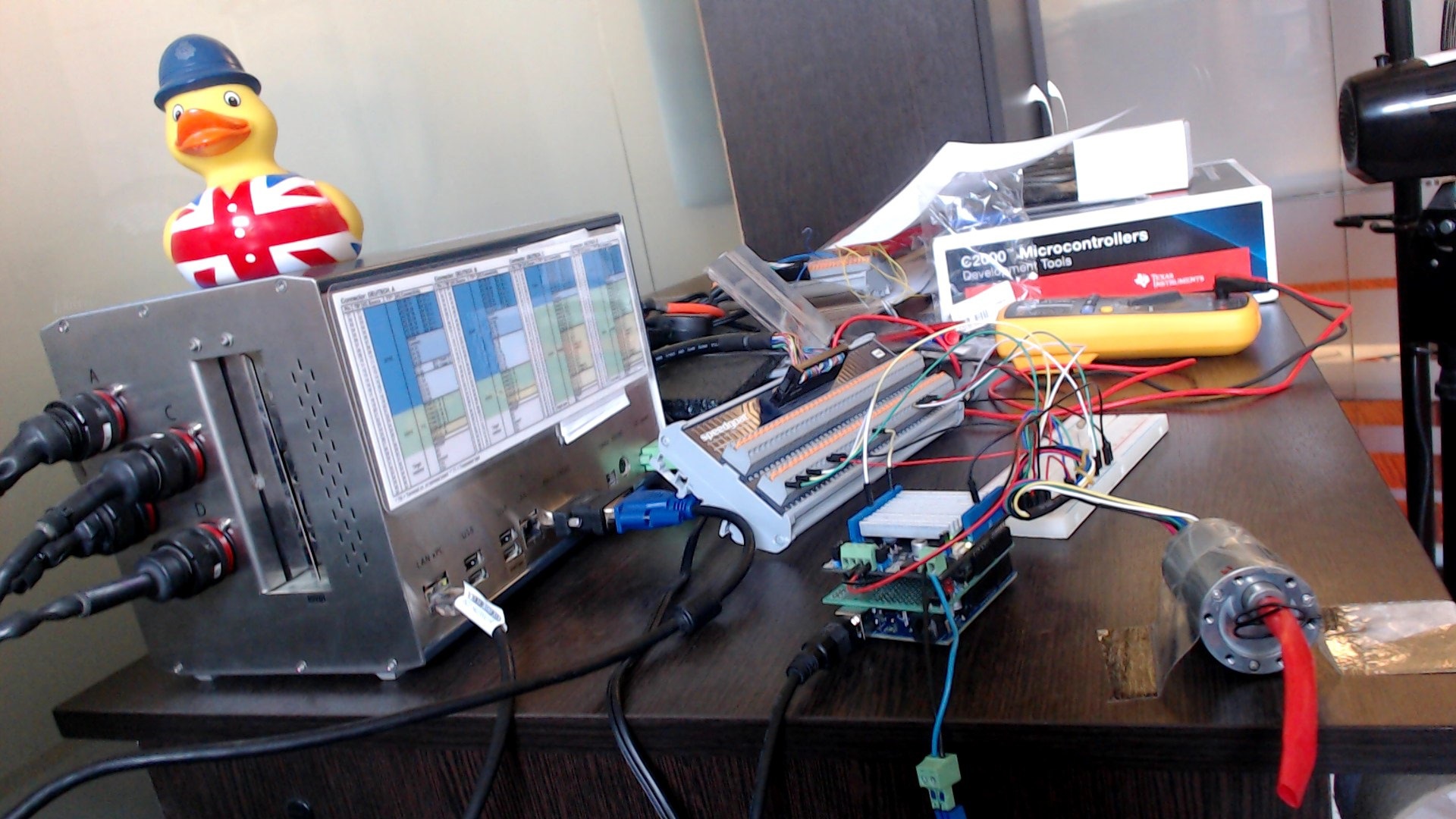
')- Speedgoat real time machine . A little easier than in the title illustration, something like this:
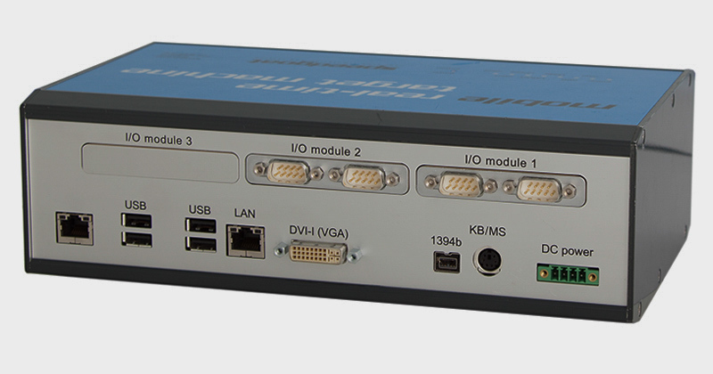
In this PC (and this is essentially IBM compatible PC) there are I / O boards with analog, discrete, and other inputs and outputs, which I use both for data collection and for controlling the course of the experiment. But the most important thing is that with one click I can launch Simulink models on it in hard real-time mode. About such machines (forgive me diminutive further appeal to Her :-) I can still tell a lot. If interested - you can select for this a separate topic. - MATLAB / Simulink
I do not change the tools. As in my previous posts, I will use Simulink to create models, generate code from them, and run it on interesting pieces of hardware. - DC motor with encoder and gear from Pololu. Here is this:

- Seeedstudio Arduino + Motor Shield
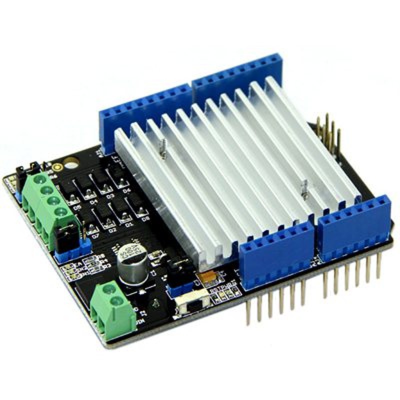
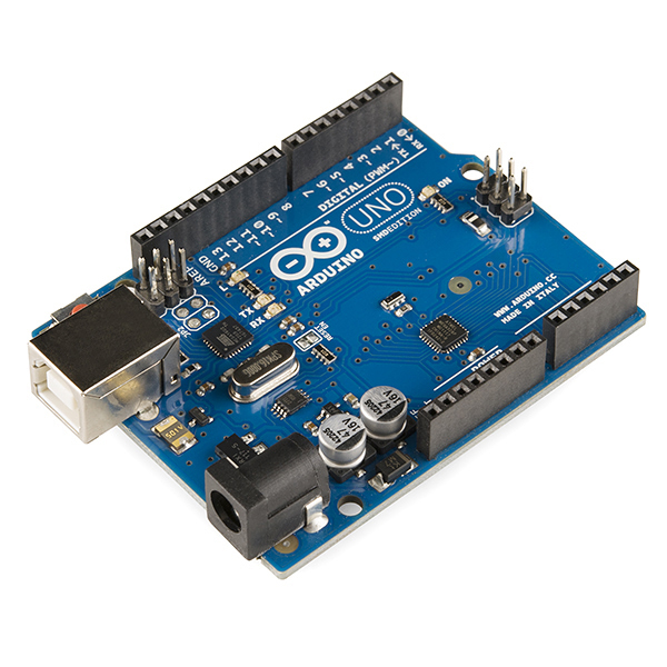
To work with Arduino from under Simulink, I use the Embedded Coder Target for Arduino library.
This library allows you to use Simulink models to generate code that is completely ready for compilation for this platform. You can also use the built-in support for Arduino in MATLAB / Simulink , but I like this target more. - Development board, conductors, power and other small things
In fact, any of the presented components can be replaced by the corresponding functional counterpart (except for the duck, of course!). But, since everything was done “on the knee”, then the right of choice remains with the owner of this important joint.
When assembled, if it can be called self-discipline, everything looks like this:
Formulation of the problem
There is a system - you need to get its model for further work. There is simply no place.
The behavior of the system and its model should coincide as much as possible within the limits of admissible input effects. The black box method implies that we will not, or almost will not, take into account the physics of the processes within the system, but will consider it from a general point of view of control theory.
I will not go into details this time, at first everything is already visible, by sight.
But it should be noted that the most important and most interesting topics remain behind the scenes - experiment planning ( DOE ) and analysis of variance ( ANOVA ), which deserve separate consideration.
The target system in some approximation and simplification consists of the following set of subsystems:
- Discrete Subsystem - Arduino
- Continuous mechanical subsystem - engine
- Continuous Electrical Subsystem - Motor Shield
The system input is the specified PWM value of 0-100% .
There is an opportunity to change the PWM signal's duty cycle, giving uint8 values from 0 to 255 to the output of the “analog” Arduino port. It is necessary to find out how the power electronics and the engine will react to this effect.
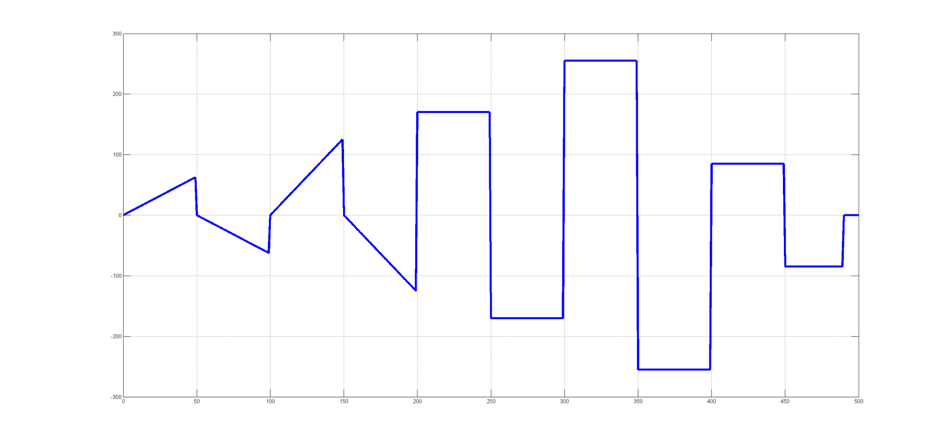
The test vector will be sewn into the controller, it consists of 501 elements and is issued with a sampling rate of 0.04s. Total ~ 20 seconds of test exposure.
The test vector looks like this:
At the output of the system, I expect to see at least something like that :-)
For successful identification, the test vector must cover the maximum number of modes of the system in which it will, or can work. The “black box” method does not allow to fully investigate emergency conditions due to the limited number of experimental samples. I will explore the system in soft start and start-stop modes.
System output - shaft rotation speed, shaft rotation angle. From the quadrature encoder, when the motor shaft is rotated, I get two meanders with a phase shift of pi / 2. They are processed by a hardware decoder, which is present on one of the configurable I / O cards. When the Simulink model is loaded onto a real-time machine, the FPGA firmware is “flashed” to provide the required I / O. Ticks, from the decoder multiply by a factor and turn into a corner, and the rate of change of their number in the speed. The engine encoder makes 64 triggers per revolution, which allows tracking the parameters described above with good accuracy. The main algorithm on a real-time machine is set by me to work with a frequency of 10 kHz - at the output I get experimental data with a sampling period of 0.0001 s . The hardware part of the FPGA operates at a frequency of 33 MHz , which allows, in addition to the basic decoding algorithm, to have time to apply anti-bounce algorithms without compromising the accuracy of measurements at fairly high speeds. Simple words decoding the quadrature signal on an FPGA is described in the excellent article fpga4fun -> QuadratureDecoder .
Discretization of values, time delays, moments of inertia of mechanical parts, calm friction, sliding friction, rolling friction, mechanical backlash, imbalance, resonant phenomena, switching inductive circuits, sliding contact, sparking - not a complete list of factors that we would have to face when trying describe this system analytically. But this is just an arduinka with a motor !
I agree, some nuances can be completely neglected, but in practice, the decision to neglect any factor is not the easiest solution.
This is the Arduino PWM (yellow) and the voltage on a purely resistive load, which is connected to the shield:
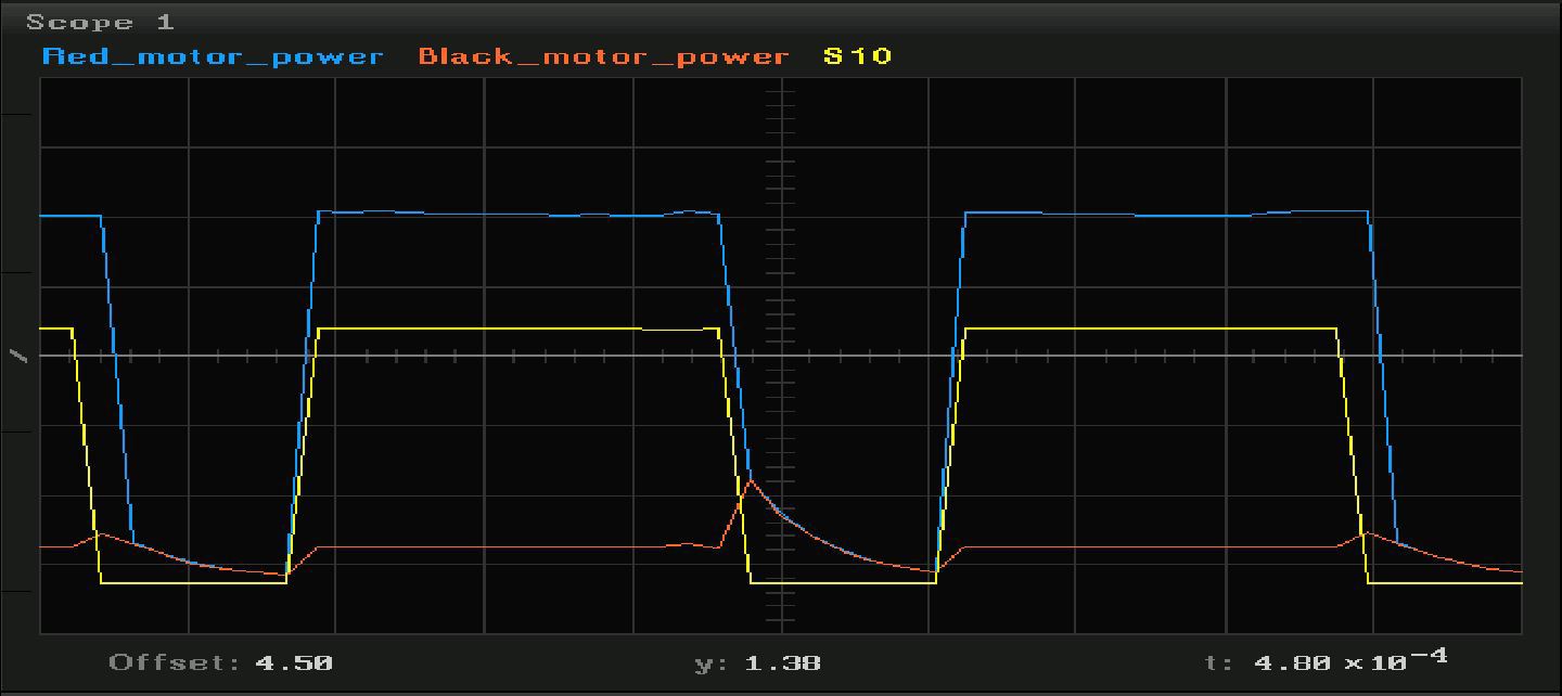
But the graphics when the engine is connected in the modes when the engine is not yet rotating, and is already rotating:
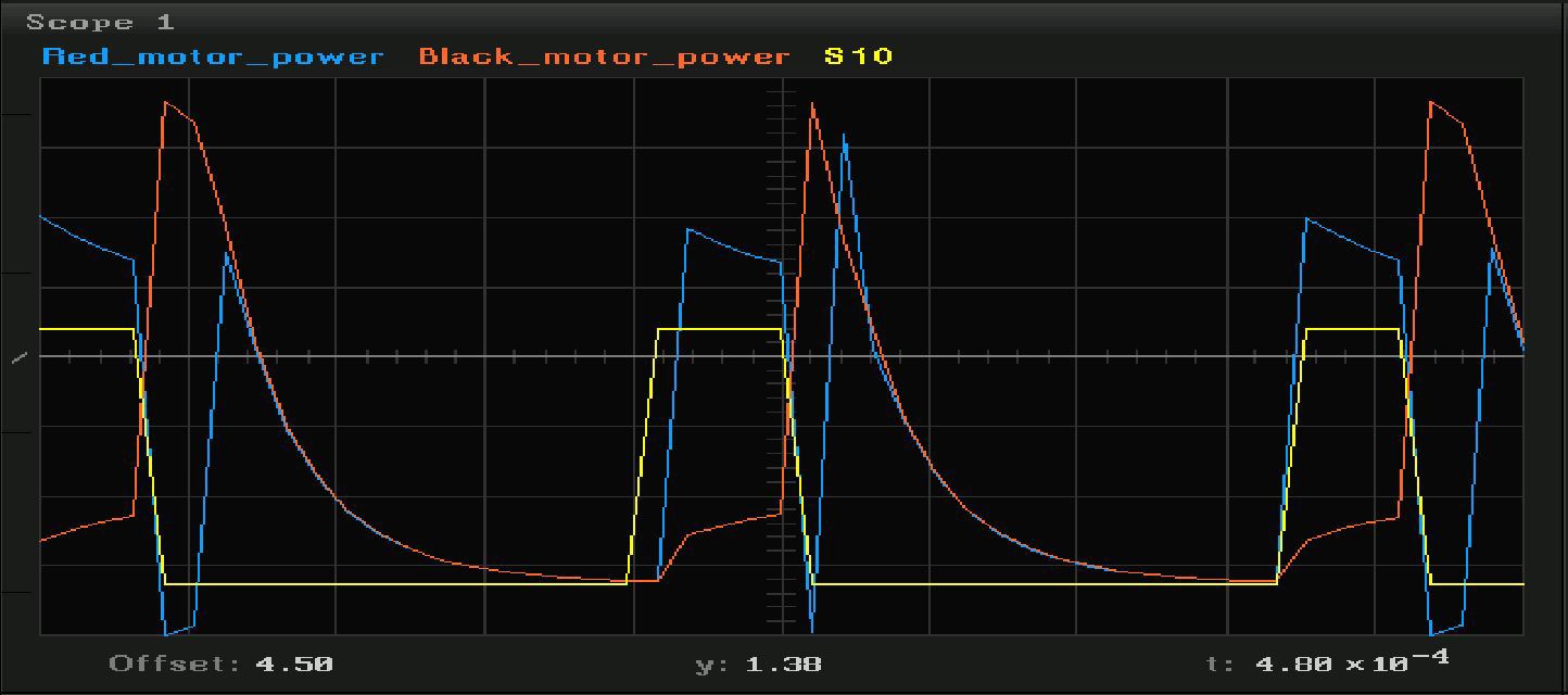
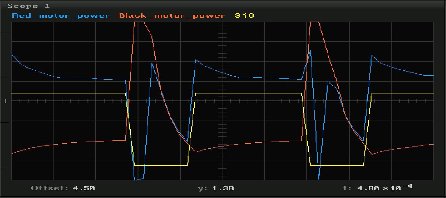
Switching inductive loads with mechanical contact with semiconductor keys is an extremely interesting topic for research, but today we will not pay attention to it. We will cut in a straight line - we will consider only the input and output of the system, without delving into the physics of processes.
Simulink models
I run this model on a real-time machine:
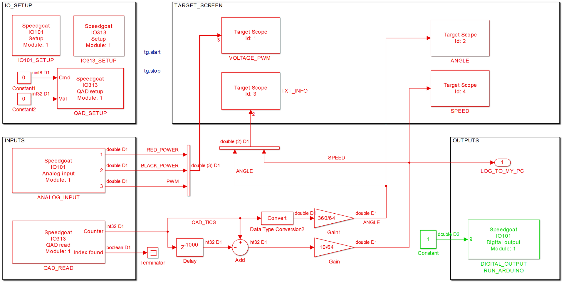
Its structure is extremely simple. There are blocks for inputs, outputs, general settings for I / O boards, information output on the machine display and simple internal logic for recalculating ticks from a quadrature encoder to an angle and speed.
The model for obtaining firmware for Arduino is as follows:

A truth table that tracks the signal mark and controls the inputs of the motor shield.

The algorithm code can be viewed under the spoiler:
C ++
The whole project can be downloaded here .// // File: arduinoTestVector.cpp // // Code generated for Simulink model 'arduinoTestVector'. // // Model version : 1.229 // Simulink Coder version : 8.6 (R2014a) 27-Dec-2013 // C/C++ source code generated on : Thu May 22 14:47:55 2014 // // Target selection: arduino_ec.tlc // Embedded hardware selection: Atmel->AVR // Code generation objectives: // 1. Execution efficiency // 2. ROM efficiency // 3. RAM efficiency // Validation result: Not run // #include "arduinoTestVector.h" // Constant parameters (auto storage) const ConstParam_arduinoTestVector arduinoTestVector_ConstP = { // Expression: myData // Referenced by: '<S1>/Constant1' { 0, 1, 3, 4, 5, 6, 8, 9, 10, 11, 13, 14, 15, 17, 18, 19, 20, 22, 23, 24, 26, 27, 28, 29, 31, 32, 33, 34, 36, 37, 38, 40, 41, 42, 43, 45, 46, 47, 48, 50, 51, 52, 54, 55, 56, 57, 59, 60, 61, 62, 0, -1, -3, -4, -5, -6, -8, -9, -10, -11, -13, -14, -15, -17, -18, -19, -20, -22, -23, -24, -26, -27, -28, -29, -31, -32, -33, -34, -36, -37, -38, -40, -41, -42, -43, -45, -46, -47, -48, -50, -51, -52, -54, -55, -56, -57, -59, -60, -61, -62, 0, 3, 5, 8, 10, 13, 15, 18, 20, 23, 26, 28, 31, 33, 36, 38, 41, 43, 46, 48, 51, 54, 56, 59, 61, 64, 66, 69, 71, 74, 77, 79, 82, 84, 87, 89, 92, 94, 97, 99, 102, 105, 107, 110, 112, 115, 117, 120, 122, 125, 0, -3, -5, -8, -10, -13, -15, -18, -20, -23, -26, -28, -31, -33, -36, -38, -41, -43, -46, -48, -51, -54, -56, -59, -61, -64, -66, -69, -71, -74, -77, -79, -82, -84, -87, -89, -92, -94, -97, -99, -102, -105, -107, -110, -112, -115, -117, -120, -122, -125, 170, 170, 170, 170, 170, 170, 170, 170, 170, 170, 170, 170, 170, 170, 170, 170, 170, 170, 170, 170, 170, 170, 170, 170, 170, 170, 170, 170, 170, 170, 170, 170, 170, 170, 170, 170, 170, 170, 170, 170, 170, 170, 170, 170, 170, 170, 170, 170, 170, 170, -170, -170, -170, -170, -170, -170, -170, -170, -170, -170, -170, -170, -170, -170, -170, -170, -170, -170, -170, -170, -170, -170, -170, -170, -170, -170, -170, -170, -170, -170, -170, -170, -170, -170, -170, -170, -170, -170, -170, -170, -170, -170, -170, -170, -170, -170, -170, -170, -170, -170, 255, 255, 255, 255, 255, 255, 255, 255, 255, 255, 255, 255, 255, 255, 255, 255, 255, 255, 255, 255, 255, 255, 255, 255, 255, 255, 255, 255, 255, 255, 255, 255, 255, 255, 255, 255, 255, 255, 255, 255, 255, 255, 255, 255, 255, 255, 255, 255, 255, 255, -255, -255, -255, -255, -255, -255, -255, -255, -255, -255, -255, -255, -255, -255, -255, -255, -255, -255, -255, -255, -255, -255, -255, -255, -255, -255, -255, -255, -255, -255, -255, -255, -255, -255, -255, -255, -255, -255, -255, -255, -255, -255, -255, -255, -255, -255, -255, -255, -255, -255, 85, 85, 85, 85, 85, 85, 85, 85, 85, 85, 85, 85, 85, 85, 85, 85, 85, 85, 85, 85, 85, 85, 85, 85, 85, 85, 85, 85, 85, 85, 85, 85, 85, 85, 85, 85, 85, 85, 85, 85, 85, 85, 85, 85, 85, 85, 85, 85, 85, 85, -85, -85, -85, -85, -85, -85, -85, -85, -85, -85, -85, -85, -85, -85, -85, -85, -85, -85, -85, -85, -85, -85, -85, -85, -85, -85, -85, -85, -85, -85, -85, -85, -85, -85, -85, -85, -85, -85, -85, -85, 0, 0, 0, 0, 0, 0, 0, 0, 0, 0, 0 } }; // Block signals (auto storage) BlockIO_arduinoTestVector arduinoTestVector_B; // Block states (auto storage) D_Work_arduinoTestVector arduinoTestVector_DWork; // Model step function void arduinoTestVector_step(void) { // local block i/o variables uint8_T rtb_MOTORSHIELD_IN1; uint8_T rtb_MOTORSHIELD_IN2; uint8_T rtb_Abs; boolean_T aVarTruthTableCondition_1; boolean_T aVarTruthTableCondition_2; boolean_T aVarTruthTableCondition_3; uint16_T rtb_Init; // Outputs for Enabled SubSystem: '<Root>/ENABLE_TEST' incorporates: // EnablePort: '<S1>/Enable' // S-Function (sfunar_digitalInput): '<Root>/RUN_TEST' if (((uint8_T)digitalRead(((uint8_T)2U))) > 0) { if (!arduinoTestVector_DWork.ENABLE_TEST_MODE) { // InitializeConditions for UnitDelay: '<S1>/Unit Delay' arduinoTestVector_DWork.UnitDelay_DSTATE = false; // InitializeConditions for UnitDelay: '<S4>/FixPt Unit Delay2' arduinoTestVector_DWork.FixPtUnitDelay2_DSTATE = 1U; // InitializeConditions for UnitDelay: '<S4>/FixPt Unit Delay1' arduinoTestVector_DWork.FixPtUnitDelay1_DSTATE = 0U; arduinoTestVector_DWork.ENABLE_TEST_MODE = true; } // Switch: '<S4>/Init' incorporates: // Constant: '<S4>/Initial Condition' // Logic: '<S4>/FixPt Logical Operator' // UnitDelay: '<S1>/Unit Delay' // UnitDelay: '<S4>/FixPt Unit Delay1' // UnitDelay: '<S4>/FixPt Unit Delay2' if (arduinoTestVector_DWork.UnitDelay_DSTATE || (arduinoTestVector_DWork.FixPtUnitDelay2_DSTATE != 0)) { rtb_Init = 0U; } else { rtb_Init = arduinoTestVector_DWork.FixPtUnitDelay1_DSTATE; } // End of Switch: '<S4>/Init' // Selector: '<S1>/Selector' incorporates: // Constant: '<S1>/Constant1' arduinoTestVector_B.Selector = arduinoTestVector_ConstP.Constant1_Value [(int16_T)rtb_Init]; // Switch: '<S4>/Reset' incorporates: // UnitDelay: '<S1>/Unit Delay' if (arduinoTestVector_DWork.UnitDelay_DSTATE) { // Update for UnitDelay: '<S4>/FixPt Unit Delay1' incorporates: // Constant: '<S4>/Initial Condition' arduinoTestVector_DWork.FixPtUnitDelay1_DSTATE = 0U; } else { // Update for UnitDelay: '<S4>/FixPt Unit Delay1' incorporates: // Constant: '<S1>/Constant' // Sum: '<S1>/Add' arduinoTestVector_DWork.FixPtUnitDelay1_DSTATE = rtb_Init + 1U; } // End of Switch: '<S4>/Reset' // Update for UnitDelay: '<S1>/Unit Delay' incorporates: // Constant: '<S3>/Constant' // RelationalOperator: '<S3>/Compare' arduinoTestVector_DWork.UnitDelay_DSTATE = (rtb_Init == 500U); // Update for UnitDelay: '<S4>/FixPt Unit Delay2' incorporates: // Constant: '<S4>/FixPt Constant' arduinoTestVector_DWork.FixPtUnitDelay2_DSTATE = 0U; } else { if (arduinoTestVector_DWork.ENABLE_TEST_MODE) { // Disable for Outport: '<S1>/TEST_OUT' arduinoTestVector_B.Selector = 0; arduinoTestVector_DWork.ENABLE_TEST_MODE = false; } } // End of S-Function (sfunar_digitalInput): '<Root>/RUN_TEST' // End of Outputs for SubSystem: '<Root>/ENABLE_TEST' // Truth Table: '<Root>/Truth Table' // Truth Table Function 'Truth Table': '<S2>:1' // ClockWise // Condition '#1': '<S2>:1:10' aVarTruthTableCondition_1 = (arduinoTestVector_B.Selector > 0); // CounterClockWise // Condition '#2': '<S2>:1:14' aVarTruthTableCondition_2 = (arduinoTestVector_B.Selector < 0); // Stop // Condition '#3': '<S2>:1:18' aVarTruthTableCondition_3 = (arduinoTestVector_B.Selector == 0); if ((!aVarTruthTableCondition_1) && (!aVarTruthTableCondition_2) && aVarTruthTableCondition_3) { // Decision 'D1': '<S2>:1:20' // Stop // Action '3': '<S2>:1:48' rtb_MOTORSHIELD_IN1 = 0U; // Action '3': '<S2>:1:49' rtb_MOTORSHIELD_IN2 = 0U; } else { // Decision 'D2': '<S2>:1:20' if (aVarTruthTableCondition_1 && (!aVarTruthTableCondition_2) && (!aVarTruthTableCondition_3)) { // Decision 'D2': '<S2>:1:22' // ClockWise // Action '1': '<S2>:1:34' rtb_MOTORSHIELD_IN1 = 1U; // Action '1': '<S2>:1:35' rtb_MOTORSHIELD_IN2 = 0U; } else { // Decision 'D3': '<S2>:1:22' if ((!aVarTruthTableCondition_1) && aVarTruthTableCondition_2 && (!aVarTruthTableCondition_3)) { // Decision 'D3': '<S2>:1:24' // CounterClockWise // Action '2': '<S2>:1:41' rtb_MOTORSHIELD_IN1 = 0U; // Action '2': '<S2>:1:42' rtb_MOTORSHIELD_IN2 = 1U; } else { // Decision 'D4': '<S2>:1:24' // Decision 'D4': '<S2>:1:26' // Default // None // Action '4': '<S2>:1:55' rtb_MOTORSHIELD_IN1 = 0U; // Action '4': '<S2>:1:56' rtb_MOTORSHIELD_IN2 = 0U; } } } // End of Truth Table: '<Root>/Truth Table' // S-Function (sfunar_digitalOutput): '<Root>/MOTORSHIELD_IN1' digitalWrite(((uint8_T)8U), rtb_MOTORSHIELD_IN1); // S-Function (sfunar_digitalOutput): '<Root>/MOTORSHIELD_IN2' digitalWrite(((uint8_T)11U), rtb_MOTORSHIELD_IN2); // Abs: '<Root>/Abs' if (arduinoTestVector_B.Selector < 0) { rtb_Abs = (uint8_T)-arduinoTestVector_B.Selector; } else { rtb_Abs = (uint8_T)arduinoTestVector_B.Selector; } // End of Abs: '<Root>/Abs' // S-Function (sfunar_analogOutput): '<Root>/SPEEDPIN_A' analogWrite(((uint8_T)9U), rtb_Abs); } // Model initialize function void arduinoTestVector_initialize(void) { // Registration code // block I/O (void) memset(((void *) &arduinoTestVector_B), 0, sizeof(BlockIO_arduinoTestVector)); // states (dwork) (void) memset((void *)&arduinoTestVector_DWork, 0, sizeof(D_Work_arduinoTestVector)); // S-Function (sfunar_digitalInput): <Root>/RUN_TEST pinMode(((uint8_T)2U), INPUT); // InitializeConditions for Enabled SubSystem: '<Root>/ENABLE_TEST' // InitializeConditions for UnitDelay: '<S1>/Unit Delay' arduinoTestVector_DWork.UnitDelay_DSTATE = false; // InitializeConditions for UnitDelay: '<S4>/FixPt Unit Delay2' arduinoTestVector_DWork.FixPtUnitDelay2_DSTATE = 1U; // InitializeConditions for UnitDelay: '<S4>/FixPt Unit Delay1' arduinoTestVector_DWork.FixPtUnitDelay1_DSTATE = 0U; // End of InitializeConditions for SubSystem: '<Root>/ENABLE_TEST' // S-Function (sfunar_digitalOutput): <Root>/MOTORSHIELD_IN1 pinMode(((uint8_T)8U), OUTPUT); // S-Function (sfunar_digitalOutput): <Root>/MOTORSHIELD_IN2 pinMode(((uint8_T)11U), OUTPUT); // S-Function (sfunar_analogOutput): <Root>/SPEEDPIN_A pinMode(((uint8_T)9U), OUTPUT); } // // File trailer for generated code. // // [EOF] // The model I will use to verify the results:
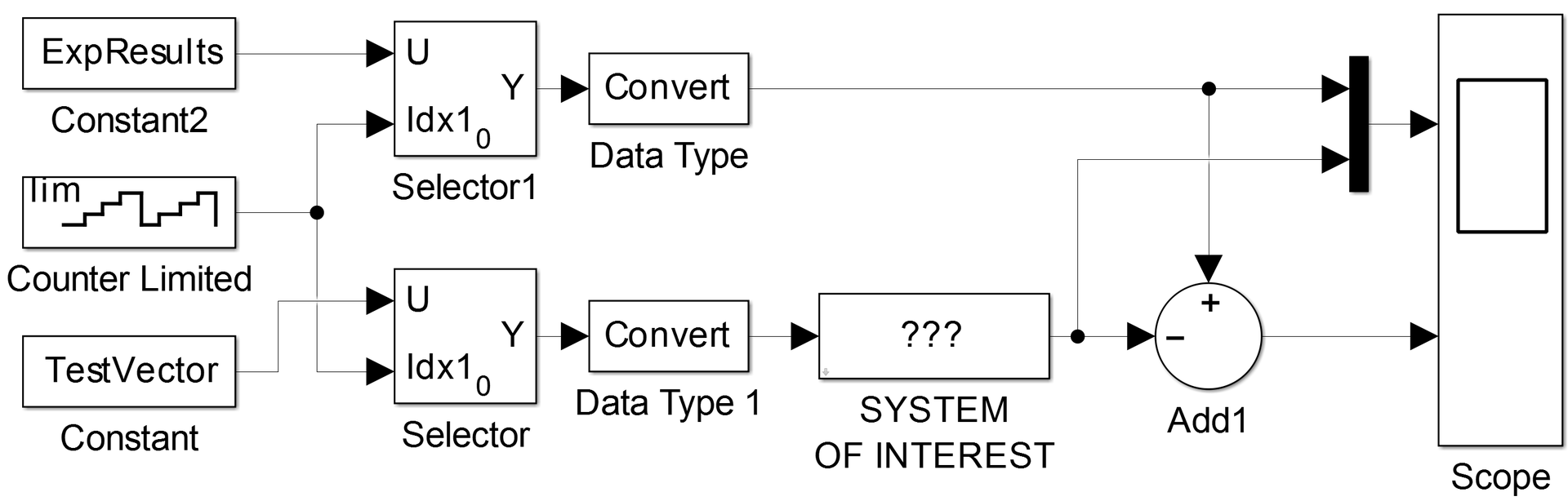
All models can be downloaded here .
"Opened and launched" may not work, there are nuances. With questions in lichku, or in the comments.
Video
results
That's what happened in the end:
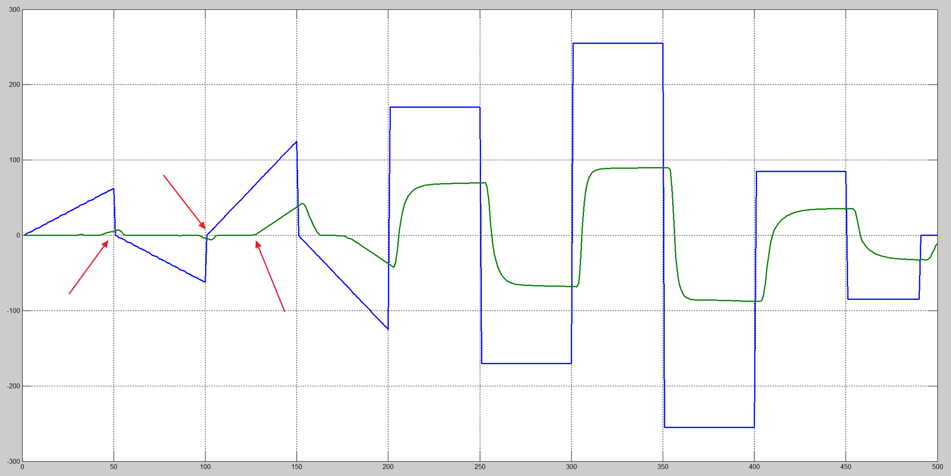
Blue is an input signal with a range from -255 to +255 . In terms of volts will be approximately from -8.5 to 8.5 .
Green - the speed of rotation of the motor shaft.
We see a time delay, no rotation, or extremely small rotation when applying PWM less than 25% . We also observe the classical aperiodic transition process.
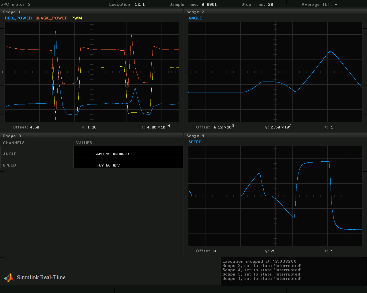
But the information that is displayed during the experiment on a display connected to a real-time machine:
Identification
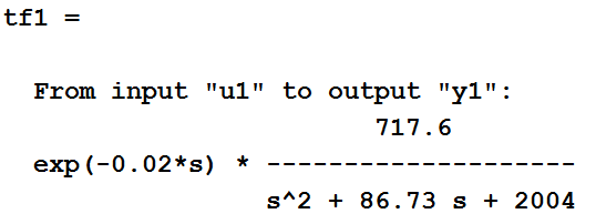
One of the subsystems, namely the engine, can be described by the following transfer function:
So tells us the course TAU, with it we begin.
MATLAB has a great system identification tool called System Identification Toolbox . It is available both as a graphical interface and as a set of functions that can be used in MATLAB scripts. Consider first the work in the graphical interface.
We import the data obtained during the experiment and test impact:
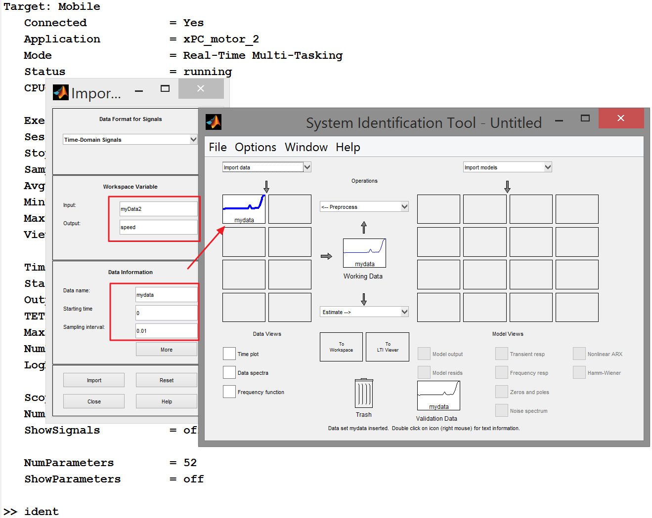
After the import, the data preprocessing tools become available to us. We have the opportunity, for example, to divide data arrays into two parts - for identification and separately for verification. But this is for more complex cases, let's get down to business soon!
Select the Transfer Function Models item from the “Estimate” drop-down list.
Get the transfer function:
Let's compare the behavior of the resulting function and the system:
The blue shows the response of the transfer function to the original test vector. It is seen that this function can be used as a model of the original system only in the start-stop mode. And not surprisingly, the nonlinear behavior that is present in the system cannot be described in this way.
Go ahead, use the Hammerstein-Wiener model pattern, which makes it possible to describe the non-linear behavior of the system:

As an input non-linearity, select Dead Zone - no system response to the input signal less than a certain threshold value. This type of nonlinearity should take on the description of the friction of calm and the influence of permanent magnets, which takes place in the system.
The rest of the default settings, click Estimate .
Update # 1 at the request of MichaelBorisov :
In more detail, setting up the non-linear part looks like this:
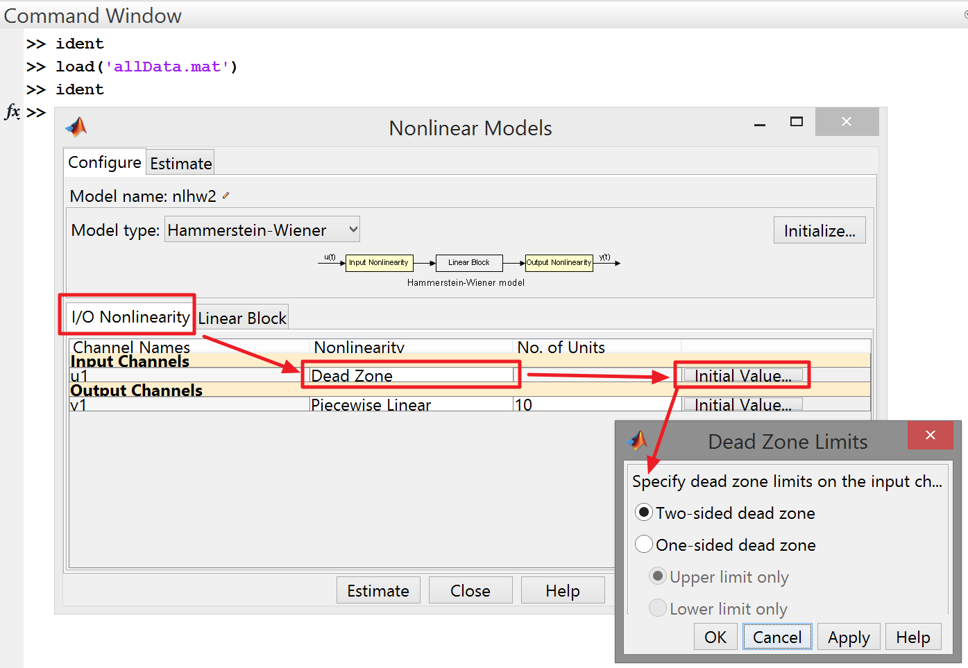
For the case of the Dead Zone, everything is simple - we set the type and threshold values.
Setting the linear part allows you to pre-specify the order and estimate the delay:

Despite the fact that this is a “black box” - in practice, obtaining an adequate result is very dependent on the amount of knowledge about the system that you have invested in the calculation configuration.
endOfUpdate # 1 at the request of MichaelBorisov :
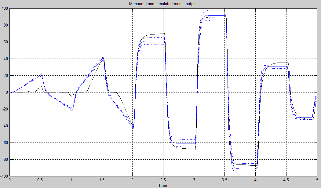
Compare the result with experimental data:

Looks much better! Not ideal - some abnormal behavior is noticeable, but we only slightly touched upon the identification of nonlinear systems.
Now we can only export this model to Simulink , where we can begin to develop a management system. But more about that in the next topic!
Thank you for your attention, I hope it was interesting?
And once again, thank you for answering a small survey:
Source: https://habr.com/ru/post/222779/
All Articles