Microprocessor "out of the garage"
Surely everyone dealing with electronics and FPGAs is familiar with the site opencores.org, where a lot of useful (and not so) solutions for electronics are collected - dozens, maybe hundreds, of processors and peripherals implementations - both original implementations of already existing devices, and so on. and new developments. This article will discuss a 32-bit microprocessor with the original command system, created on the basis of the Mars Rover 2 board .
Our team has been working on the L4 microkernel for 10 years and at some point it came to the realization that the microkernel itself can be implemented as a processor unit. Moreover, if a full-fledged microkernel is very difficult to implement in hardware, then you can at least help the software part by shifting some of the functions to hardware. First, we decided to go the easy and optimal way - to study existing solutions, choose the right one andmodify the file to add features that are useful for the microkernel. The work took about a month and almost all solutions found on opencores were studied. Taking as a basis the ready-made solution opened up quite good possibilities, in the form of ready-made compilers and various libraries. At some point, we no longer like the existing solutions - something turned out to be difficult, something suboptimal, something just unfinished, something to hide, had a not very suitable license and terms of use. Grabbing courage and gritting our teeth, we began the adventure, deciding to develop a processor from the very beginning.
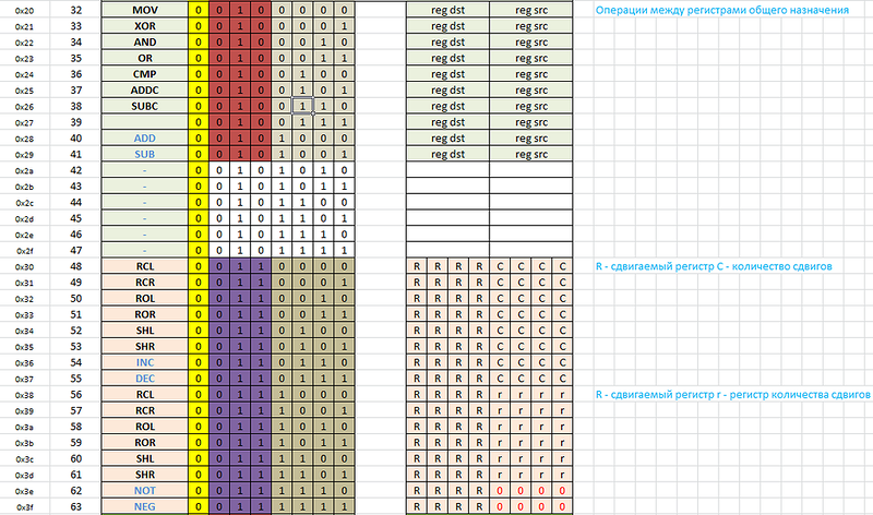
What is the beginning of the microprocessor? Ask your system programmer, and he will answer you that this is a system of commands. Despite the total fashion on RISC architecture, we decided not to tie the length of the instructions to the size of the machine word. Therefore, we conducted several experiments. Oddly enough, but a very convenient tool for designing a command system turned out to be ... Microsoft Excel. First of all, we selected a few columns, using them to number the instructions in the three numeral systems - decimal, hexadecimal and binary. The result was 256 lines, according to the number of states that can be described in one byte. Then we tried to logically group the instructions in such a way that the decoding scheme was as simple as possible. The first block of instructions was taken by single-byte instructions — prefixes, modifiers, and simple instructions. The following block of instructions looks like this:
')
At the next stage, we had to decide on the number and types of registers. How many registers do you think would be optimal for most tasks? The answers to this question can vary greatly depending on the identity of the respondent - someone and 32 lack, as it is, and adherents of non-register architecture. We decided to stop at 16 general registers. This number is quite comfortable for programming in assembler, quite successfully falls on our architecture and is easily implemented in HDL.
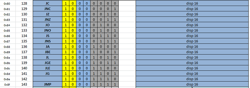
Having decided on the registers, we decided to make a completely position-independent command system — there is no absolute transition command in the architecture at the absolute address — all transitions are relative to the current command. We are simply obsessed with compactness, so all transition teams have three forms - signed displacements of 1, 2 and 3 bytes. For example, the following shows transitions with a 16-bit offset:
Finally, we abandoned the concept of a hardware stack, in favor of organizing the stack “by agreement”. For this, a special NOTCH prefix and the following scheme were introduced - if the prefix is preceded by a conditional or unconditional jump instruction, then the address of the next instruction is placed in the R15 register, i.e. return address. Accordingly, the instruction RETURN performs the transition to the contents of the register R15. Thus, with nested subroutine calls, the care of saving the return address is left to the programmer or the compiler. At first glance, this does not seem very convenient, optimal and familiar, but if you think about it, you get several advantages - firstly, you can save a few ticks without saving this register in external memory in terminal subroutines (i.e., subprograms that do not call other subroutines), secondly, the NOTCH prefix can be placed before a conditional branch instruction, thereby implementing conditional function calls — albeit small, but also saving. As for the complexity of programming in assembler, they are hidden by macros that are assembler mnemonics of a higher level.
Positional independence of the code introduces another feature - reference to constant data. Since the code can be located at an arbitrary address, the constant data can be located arbitrarily along with the code. The solution turned out to be quite simple - using the same NOTCH prefix when loading a constant into a register, uses a constant as an offset relative to the instruction being executed - this solves the problem of addressing data in a position-independent code.
After designing the command system, which generally took about a year, we armed ourselves with the Qauartus and Icarus Verilog environment and ... understood that we hurried. Implementing a command system in Verilog was damn complicated. Knowledgeable people advised to run solutions on a software model, writing a decoder and other functional devices on ordinary C. After the implementation of the emulator of a nonexistent processor and the run of test programs on it, things went better. Another half a year was needed to implement the processor on Verilog. It should be said here that for a newbie, programming an FPGA can be incredibly difficult, and many years of programming experience in high-level languages may even complicate the task. In this case, come to the aid of modeling tools. At the first stage, Icarus Verilog turned out to be extremely useful - a free tool for circuit simulation, complete with GTKWave - a program for displaying signals. Using these tools you can see what is happening with the device at any given time. At some point, Icarus Verilog’s capabilities were few and we used ModelSim’s simulator from MentorGraphis, a very powerful commercial tool, a trimmed version of which can be installed for free with the Altera Quartus environment.
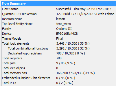
You can talk about the debugging process for a long time. And at some point, when the FPGA resources were occupied by a full third, an understanding suddenly emerged that the resulting processor could already be used for some projects.
To demonstrate the capabilities of the processor, we wrote a simple firmware that, when started, displays the following menu on the screen of the remote terminal:
If you press the 1 key and if your terminal supports file transfer using the X-modem protocol, then a file of up to 4 Kb in size can be uploaded to the device. This can be a text or an ANSI image - in this case, pressing the 5 key will display the text or image on the screen. But would it be worthwhile to write an article for this? Of course not, so when you press key 2 in the terminal, control is transferred to the code loaded via the first menu item. If you transfer control to the loaded text or the ansi-picture, then in a few steps the processor will stumble upon a non-existent (still undefined command) or turn to non-existent memory. In this case, the processor will go into step-by-step mode - each code received from the terminal will cause the execution of one processor instruction with the output of the busses to the remote terminal.
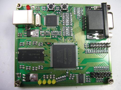
It's time to press the "Reset" button. We called the “reset” left button on the Mars Rover 2 board.
To make the device do something meaningful, you need Macro Assembler . In this archive, in addition to the assembler and a few examples, we put the source code of the processor microcode. Below is an example of a simple user program that can be translated into a binary file using an assembler and loaded into the processor.
This program in a cycle, before pressing any key in the terminal, displays to the remote terminal information about the number of seconds since the start or reset of the device. To check it in business, you will need the generated file usr_demo2.bin .
A small explanation of the program. The _get_sysclock subroutine returns the number of pulses of the crystal oscillator since the device was turned on or reset. Sample subroutine dump:
When exiting the _get_sysclock subroutine, the R0 register contains the lower 32 bits, and the R1 register contains the higher 32-bits of the result.
The constant 0x05F5E100 is the number of clock pulses per second.
You can download the latest firmware version for the Mars Rover 2 card at this link .
If you do not hear the news from our project, then you should know that we are working on transferring the L4 microkernel to the FPGA.
Thanks for attention.
Our team has been working on the L4 microkernel for 10 years and at some point it came to the realization that the microkernel itself can be implemented as a processor unit. Moreover, if a full-fledged microkernel is very difficult to implement in hardware, then you can at least help the software part by shifting some of the functions to hardware. First, we decided to go the easy and optimal way - to study existing solutions, choose the right one and
What is the beginning of the microprocessor? Ask your system programmer, and he will answer you that this is a system of commands. Despite the total fashion on RISC architecture, we decided not to tie the length of the instructions to the size of the machine word. Therefore, we conducted several experiments. Oddly enough, but a very convenient tool for designing a command system turned out to be ... Microsoft Excel. First of all, we selected a few columns, using them to number the instructions in the three numeral systems - decimal, hexadecimal and binary. The result was 256 lines, according to the number of states that can be described in one byte. Then we tried to logically group the instructions in such a way that the decoding scheme was as simple as possible. The first block of instructions was taken by single-byte instructions — prefixes, modifiers, and simple instructions. The following block of instructions looks like this:
')
At the next stage, we had to decide on the number and types of registers. How many registers do you think would be optimal for most tasks? The answers to this question can vary greatly depending on the identity of the respondent - someone and 32 lack, as it is, and adherents of non-register architecture. We decided to stop at 16 general registers. This number is quite comfortable for programming in assembler, quite successfully falls on our architecture and is easily implemented in HDL.
Having decided on the registers, we decided to make a completely position-independent command system — there is no absolute transition command in the architecture at the absolute address — all transitions are relative to the current command. We are simply obsessed with compactness, so all transition teams have three forms - signed displacements of 1, 2 and 3 bytes. For example, the following shows transitions with a 16-bit offset:
Finally, we abandoned the concept of a hardware stack, in favor of organizing the stack “by agreement”. For this, a special NOTCH prefix and the following scheme were introduced - if the prefix is preceded by a conditional or unconditional jump instruction, then the address of the next instruction is placed in the R15 register, i.e. return address. Accordingly, the instruction RETURN performs the transition to the contents of the register R15. Thus, with nested subroutine calls, the care of saving the return address is left to the programmer or the compiler. At first glance, this does not seem very convenient, optimal and familiar, but if you think about it, you get several advantages - firstly, you can save a few ticks without saving this register in external memory in terminal subroutines (i.e., subprograms that do not call other subroutines), secondly, the NOTCH prefix can be placed before a conditional branch instruction, thereby implementing conditional function calls — albeit small, but also saving. As for the complexity of programming in assembler, they are hidden by macros that are assembler mnemonics of a higher level.
Positional independence of the code introduces another feature - reference to constant data. Since the code can be located at an arbitrary address, the constant data can be located arbitrarily along with the code. The solution turned out to be quite simple - using the same NOTCH prefix when loading a constant into a register, uses a constant as an offset relative to the instruction being executed - this solves the problem of addressing data in a position-independent code.
After designing the command system, which generally took about a year, we armed ourselves with the Qauartus and Icarus Verilog environment and ... understood that we hurried. Implementing a command system in Verilog was damn complicated. Knowledgeable people advised to run solutions on a software model, writing a decoder and other functional devices on ordinary C. After the implementation of the emulator of a nonexistent processor and the run of test programs on it, things went better. Another half a year was needed to implement the processor on Verilog. It should be said here that for a newbie, programming an FPGA can be incredibly difficult, and many years of programming experience in high-level languages may even complicate the task. In this case, come to the aid of modeling tools. At the first stage, Icarus Verilog turned out to be extremely useful - a free tool for circuit simulation, complete with GTKWave - a program for displaying signals. Using these tools you can see what is happening with the device at any given time. At some point, Icarus Verilog’s capabilities were few and we used ModelSim’s simulator from MentorGraphis, a very powerful commercial tool, a trimmed version of which can be installed for free with the Altera Quartus environment.
You can talk about the debugging process for a long time. And at some point, when the FPGA resources were occupied by a full third, an understanding suddenly emerged that the resulting processor could already be used for some projects.
To demonstrate the capabilities of the processor, we wrote a simple firmware that, when started, displays the following menu on the screen of the remote terminal:
 ────────────────────────> Welcome to Everest core <──────────────────── ────────┐
 │ 1 - Load binary file via X-modem protocol │
 │ 2 - Run previously loaded binary file
 │ 3 - Show RAM (0x100000-0x100140)
 │ 4 - Test of message registers
 │ 5 - Show previously loaded ANSI picture
 │ 6 - Show built-in ANSI pic # 1
 │ 7 - Show built-in ANSI pic # 2
 ────────────────────────────────────────────────── ─────────────────────────────┘
If you press the 1 key and if your terminal supports file transfer using the X-modem protocol, then a file of up to 4 Kb in size can be uploaded to the device. This can be a text or an ANSI image - in this case, pressing the 5 key will display the text or image on the screen. But would it be worthwhile to write an article for this? Of course not, so when you press key 2 in the terminal, control is transferred to the code loaded via the first menu item. If you transfer control to the loaded text or the ansi-picture, then in a few steps the processor will stumble upon a non-existent (still undefined command) or turn to non-existent memory. In this case, the processor will go into step-by-step mode - each code received from the terminal will cause the execution of one processor instruction with the output of the busses to the remote terminal.
It's time to press the "Reset" button. We called the “reset” left button on the Mars Rover 2 board.
To make the device do something meaningful, you need Macro Assembler . In this archive, in addition to the assembler and a few examples, we put the source code of the processor microcode. Below is an example of a simple user program that can be translated into a binary file using an assembler and loaded into the processor.
function user_main load r14, 0x2000 push r15 loop: call _get_sysclock load r2, 0x05F5E100 call _div64 call _print_dec lea r1, $shw_str call _puts call _uart_status rcr r0, 2 ; RCV_RDY jc done ; load r0, 0x01000000 call _delay jmp loop done: pop r15 return end include tty.asm include delay.asm include mul.asm include div.asm include print_dec.asm include sysclock.asm $shw_str db ' seconds since boot',13,10,0 This program in a cycle, before pressing any key in the terminal, displays to the remote terminal information about the number of seconds since the start or reset of the device. To check it in business, you will need the generated file usr_demo2.bin .
A small explanation of the program. The _get_sysclock subroutine returns the number of pulses of the crystal oscillator since the device was turned on or reset. Sample subroutine dump:
; ------------------- _get_sysclock ------------------ 0198: 37 e3 ; DEC R14, 4 019a: 60 e3 ; MOV (R14), R3 019c: e3 ff fe ff f8 ; LOAD R3, 0xfffefff8 01a1: 68 03 ; MOV R0, (R3) 01a3: 36 33 ; INC R3, 4 01a5: 68 13 ; MOV R1, (R3) 01a7: 68 3e ; MOV R3, (R14) 01a9: 36 e3 ; INC R14, 4 01ab: 05 ; RETURN When exiting the _get_sysclock subroutine, the R0 register contains the lower 32 bits, and the R1 register contains the higher 32-bits of the result.
The constant 0x05F5E100 is the number of clock pulses per second.
You can download the latest firmware version for the Mars Rover 2 card at this link .
If you do not hear the news from our project, then you should know that we are working on transferring the L4 microkernel to the FPGA.
Thanks for attention.
Source: https://habr.com/ru/post/222335/
All Articles