Hardware Number Sorter Verilog
In this article of mine, like the previous one , digital circuitry is viewed from the programmer’s point of view. But this time the “more algorithmic” problem of sorting numbers will be parsed, with the verilog code parsing. The considered hardware solution allows you to sort n numbers in time 2 * n. The picture shows the output from the test project for the FPGA to the monitor, where each line corresponds to one sorter tick, first n ticks random numbers are written to the sorter, then n ticks the sorted numbers are displayed.

')
It is known that software sorting of n numbers in general takes time O (n * log (n)). The hardware allows you to circumvent this limitation, by performing several comparisons at once, see, for example , sorting networks . The network of sorting works entirely in parallel, data comes and goes together, my module accepts or issues only one number at a time, but does not require additional time: First, N <Nmax numbers are written to the buffer in N ticks, then N ticks are read from there (taken) sorted sequence.
UPDATE: in the comments I was convinced that this does not give the right to talk about the complexity of the algorithm o (n). If N> Nmax, then it is necessary to sort by parts, then using merge sort, the elapsed time will be ~ N * log (N / Nmax). When N -> inf, this will give the same O (n * log (n)). This, however, does not negate the fact that hardware sorting is faster than software.
Let's look at the source code on verilog. Let me remind you of the main difference between HDL and a programming language - a programming language is an instruction for a performer that is executed sequentially, line by line, and a program on HDL corresponds to an electronic circuit, all parts of which work simultaneously.
But I made another implementation with the same interface, but with slightly different properties. The differences of implementations: The first is based on a chain of sorting cells, the second is based on a binary tree, in the nodes of which there are the same cells.
The first implementation allows you to add data to a partially empty buffer (for example, you can sort interrupt requests by priority), the tree after writing requires a full read.
The advantage of a tree implementation is that not the whole chain moves in the process of working, but only one branch is theoretically more energy efficient.
Generally, recursive definitions of modules is a very uncharacteristic style for a verilog. I must admit that this project is a “locomotive for the driver”. The correct approach is as follows: the goal is to write a sorter; we choose an implementation — a tree. In my case, the very idea of writing a sorter arose from the need to master the work with tree structures, - for the needs of a calculator based on combinatorial logic . I have already written a little about this project at the end of my previous, first post on Habré. The operation of a machine is reduced to the calculation of a combinatorial expression using the parallel term rewriting method. The main idea is to assign a hardware tree of cells capable of using combinators to a tree of a functional program. Theoretically, it is possible to effectively solve problems from Boolean algebra or predicate calculus, for the purposes of symbolic calculations or proof of theorems. I hope that in the coming months I will have a working version that will be able to reduce simple expressions. If you know any practical problems that fit well with pure lambda calculus or combinatorial logic, please write in the comments.
The sources of the modules of the sorters are here under the LGPL, there are test projects for the Mars Rover 2 , Terasic DE0 and DE2-115 boards.
ps I apologize for the re-creation of the topic. Now I know that it is impossible to remove a freshly published topic in drafts for a long time on the first day.
')
It is known that software sorting of n numbers in general takes time O (n * log (n)). The hardware allows you to circumvent this limitation, by performing several comparisons at once, see, for example , sorting networks . The network of sorting works entirely in parallel, data comes and goes together, my module accepts or issues only one number at a time, but does not require additional time: First, N <Nmax numbers are written to the buffer in N ticks, then N ticks are read from there (taken) sorted sequence.
UPDATE: in the comments I was convinced that this does not give the right to talk about the complexity of the algorithm o (n). If N> Nmax, then it is necessary to sort by parts, then using merge sort, the elapsed time will be ~ N * log (N / Nmax). When N -> inf, this will give the same O (n * log (n)). This, however, does not negate the fact that hardware sorting is faster than software.
The picture gives a conditional description of the basic version of the algorithm. Hopefully, the meaning can be caught.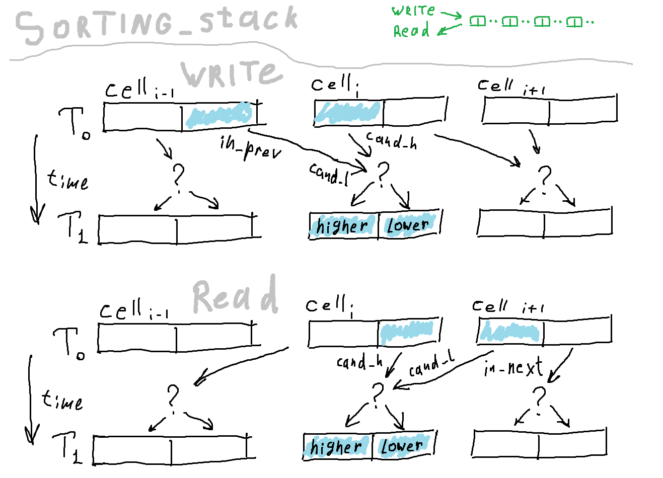
Let's look at the source code on verilog. Let me remind you of the main difference between HDL and a programming language - a programming language is an instruction for a performer that is executed sequentially, line by line, and a program on HDL corresponds to an electronic circuit, all parts of which work simultaneously.
Let's sort the source code of the sorter - chains.
We define the module of the whole chain. it has inputs, outputs, and internal modules, all of which must be connected into a single network using a combinational circuit. There are no explicit registers here, they are encapsulated inside sorting cells.
Let us consider in more detail the substitution of one module into another
Cell_Compare - module type
# (HBIT) - setting numeric parameters
ribbon - instance name
[_R_SZ] is an array, we specify the quantity
(clk, hold, is_input, - common signals for all
in_prev, in_next, out); - specific signals for each element of the array.
Next, generate is a useful construct that allows
apply cycles, etc. when describing combinational circuits.
Now the module of the sorting cell.
Here begins the actual sorting logic. Each cell stores two numbers, one smaller than the other. Each clock (if not hold ) cell compares the number that came from a neighbor with its "champion". Champion - the maximum number when writing and the minimum when reading. The loser will leave the cell on the next measure. As a result, the data moves along the chain, first in one direction, then in another. The number of numbers that fit in the device is equal to twice the number of cells.
Let's go back to the source code. Here, when describing the output, a selector is applied (compiled into a multiplexer). is_input determines whether we read data or write, it depends on it in which direction the data moves along the chain.
Everything.
// module Sorting_Stack ( clk, hold, is_input, data_in, data_out ); // parameter HBIT= 15; // size of number in bits parameter R_SZ= 256; // capacity, max sequence size parameter _R_SZ= (R_SZ+1)/2; // not to modify // - // input clk; ... // - input [HBIT:0] data_in; // load one number per clock output [HBIT:0] data_out; // while is_input==0, max value popping out here // - ... // wire [HBIT:0] in_prev[_R_SZ]; wire [HBIT:0] in_next[_R_SZ]; wire [HBIT:0] out[_R_SZ]; // - // // // storage Cell_Compare #(HBIT) ribbon[_R_SZ] ( clk, hold, is_input, in_prev, in_next, out ); Let us consider in more detail the substitution of one module into another
Cell_Compare - module type
# (HBIT) - setting numeric parameters
ribbon - instance name
[_R_SZ] is an array, we specify the quantity
(clk, hold, is_input, - common signals for all
in_prev, in_next, out); - specific signals for each element of the array.
Next, generate is a useful construct that allows
apply cycles, etc. when describing combinational circuits.
// generate genvar i,j; for (i=0; i<_R_SZ-1; i=i+1) begin : block_name01 assign in_prev[i+1]= out[i]; assign in_next[i]= out[i+1]; end assign in_prev[0]= data_in; assign data_out= out[0]; assign in_next[_R_SZ-1]= 0; endgenerate endmodule Now the module of the sorting cell.
module Cell_Compare ( clk, hold, is_input, in_prev, in_next, out ); parameter HBIT= 15; input clk; input hold; input is_input; input [HBIT:0] in_prev; input [HBIT:0] in_next; Here begins the actual sorting logic. Each cell stores two numbers, one smaller than the other. Each clock (if not hold ) cell compares the number that came from a neighbor with its "champion". Champion - the maximum number when writing and the minimum when reading. The loser will leave the cell on the next measure. As a result, the data moves along the chain, first in one direction, then in another. The number of numbers that fit in the device is equal to twice the number of cells.
Let's go back to the source code. Here, when describing the output, a selector is applied (compiled into a multiplexer). is_input determines whether we read data or write, it depends on it in which direction the data moves along the chain.
output [HBIT:0] out= is_input ? lower : higher; // . , bit [HBIT:0] higher; bit [HBIT:0] lower; // , . // , // higher in_prev (lower ), // lower in_next (higher ) wire [HBIT:0] cand_h= is_input ? higher : lower; wire [HBIT:0] cand_l= is_input ? in_prev : in_next; // . // , , // . always@(posedge clk ) if (~hold) begin // -. higher <= ( cand_h >= cand_l ) ? cand_h : cand_l; lower <= ( cand_h >= cand_l ) ? cand_l : cand_h; end endmodule Everything.
But I made another implementation with the same interface, but with slightly different properties. The differences of implementations: The first is based on a chain of sorting cells, the second is based on a binary tree, in the nodes of which there are the same cells.
The first implementation allows you to add data to a partially empty buffer (for example, you can sort interrupt requests by priority), the tree after writing requires a full read.
The advantage of a tree implementation is that not the whole chain moves in the process of working, but only one branch is theoretically more energy efficient.
Tree implementation
uses recursion to describe a binary tree, I did not even expect it to work on verilog. I will give only a sample of the recursive definition of a tree.
The logic of the movement of data on a tree is as follows: when recording, branches are selected alternately. When reading, you need to make an additional comparison to determine at the root of which subtree the number is greater. As a result, the tree needs more comparators compared to the chain of the same size. The advantage of the tree is that the data moves less, and the power consumption of the circuit strongly depends on the number of switches of the state of the registers.
module NodeType ( ); endmodule module TreeTemplate ( ); parameter TREE_LEVEL= 4; NodeType node(); generate if ( TREE_LEVEL >0 ) begin TreeTemplate #( TREE_LEVEL-1 ) leftSubtree ( ); TreeTemplate #( TREE_LEVEL-1 ) rightSubtree ( ); end endgenerate endmodule The logic of the movement of data on a tree is as follows: when recording, branches are selected alternately. When reading, you need to make an additional comparison to determine at the root of which subtree the number is greater. As a result, the tree needs more comparators compared to the chain of the same size. The advantage of the tree is that the data moves less, and the power consumption of the circuit strongly depends on the number of switches of the state of the registers.
The corresponding picture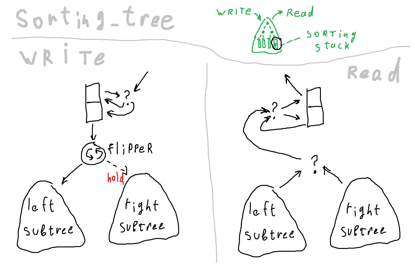
Generally, recursive definitions of modules is a very uncharacteristic style for a verilog. I must admit that this project is a “locomotive for the driver”. The correct approach is as follows: the goal is to write a sorter; we choose an implementation — a tree. In my case, the very idea of writing a sorter arose from the need to master the work with tree structures, - for the needs of a calculator based on combinatorial logic . I have already written a little about this project at the end of my previous, first post on Habré. The operation of a machine is reduced to the calculation of a combinatorial expression using the parallel term rewriting method. The main idea is to assign a hardware tree of cells capable of using combinators to a tree of a functional program. Theoretically, it is possible to effectively solve problems from Boolean algebra or predicate calculus, for the purposes of symbolic calculations or proof of theorems. I hope that in the coming months I will have a working version that will be able to reduce simple expressions. If you know any practical problems that fit well with pure lambda calculus or combinatorial logic, please write in the comments.
The sources of the modules of the sorters are here under the LGPL, there are test projects for the Mars Rover 2 , Terasic DE0 and DE2-115 boards.
ps I apologize for the re-creation of the topic. Now I know that it is impossible to remove a freshly published topic in drafts for a long time on the first day.
Source: https://habr.com/ru/post/222287/
All Articles