Turning a conventional electric convector into a wireless
Prehistory
My private house is heated with electric convectors. Everything is good in them: both ease of installation and automatic temperature control and day / night mode and 50% power mode. But there is also a minus - the air temperature sensor is fixed directly on the body of the convector, therefore it heats up and cools with it. Because of this, the convector is turned on / off much more often than desired, it is impossible to set the desired air temperature in the room, since the real one will be lower by 5 degrees, and the reliability of the permanent switching of the relay has a negative effect. It was possible, of course, to lengthen the temperature sensor and take it away, but this is not our method. Since I have been doing wireless technology for a long time and I have some experience, I decided to equip the convector with a wireless temperature sensor. This will place it anywhere in the room, do not pull the wires, and if necessary, use not one but several sensors and calculate the average room temperature. (Pictures under the cut)
Rework
As I have already said, I am deeply involved in wireless and have on this subject developments. ZigBee is the best solution for monitoring various sensors, and for a long time I have been using Jennic's JN5148 (purchased by NXP) as a ZigBee microcontroller. For the rapid production of layouts, I made myself several modules with this microcontroller.
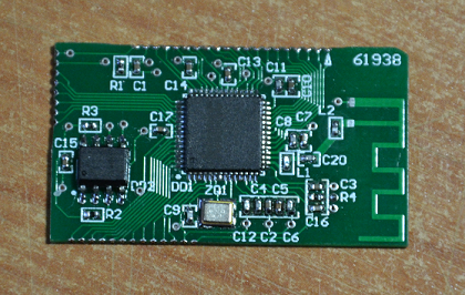
Module scheme (clickable):
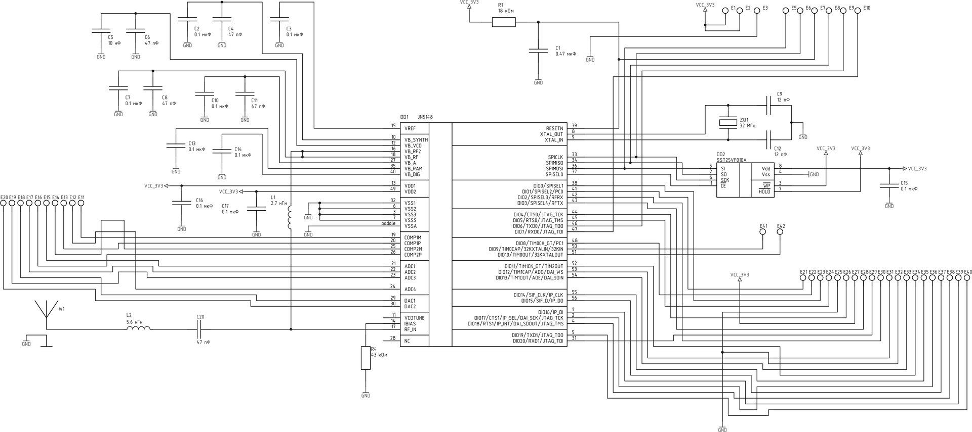
The microcontroller itself is included in the module circuit, an external program memory for it (a mandatory component for JN5148), quartz, power supply capacitors, an RF part with an antenna. For a quick start, you only need a programming connector and power supply 3.3 V. Shawls are ordered from seeedstudio, cheaply and angrily. In order to quickly something pile perfectly fit.
The temperature sensor was also made in advance and was waiting in the wings.

Sensor circuit (clickable):

A TMP102 chip from Texas Instruments was used as a temperature meter. The microcircuit is quite inexpensive, measures temperature with an accuracy of 0.5 degrees in the range of -25 .. + 85, has a current consumption of 10 μA in active mode and 1 μA in the sleeper, is very compact, and also works in the range of supply voltages from 1.4 to 3.6 V, which important when powered by a single lithium battery. Otherwise, the sensor circuit differs from the module circuit in the presence of a battery, a divider for measuring its voltage, a power switch and a programming connector.
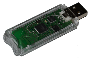
To finish with the iron and go to the actual alteration, run forward and say that at first I just wanted to measure the temperature, transfer it to the convector and somehow slip it to the microcontroller instead of its native sensor. Subsequently, the idea to set the temperature threshold as remotely, from a PC. For this, I used a USB whistle with the same JN5148.
Scheme (also clickable):

The whistle circuit includes the circuit of the module discussed above and the USB-UART converter on the FT232R microcircuit, which is also a programmer for the microcontroller.
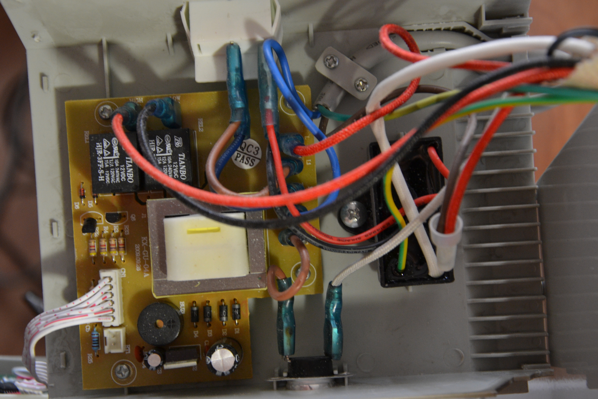
We now turn to reverse engineering. A 1000 W Ballu convector with an electronic control system was used as the test subject. Having examined the convector, I found 2 boards: power and control board.
')
Power Board:
Management fee:

On the power board there is a network power supply, voltage regulator + 5V for L7805, 2 relays, which include either a 500W (50%) load or 1000W (100%) and a buzzer. Separately located thermal fuse and air ionizer. A microcontroller, buttons and a seven-segment temperature indicator are located on the control board.
Inspection showed that a semiconductor diode is used to measure the temperature, which, as is well known, has a fairly linear dependence of the direct voltage drop on temperature. The diode is connected to the upper arm of the supply voltage divider, and the voltage from the divider is fed to the input of the microcontroller's ADC.
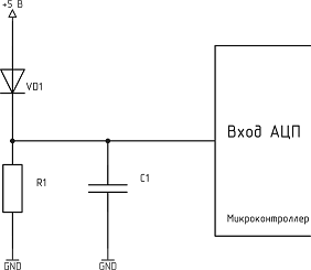
Based on this measurement scheme, the easiest way to emulate a temperature sensor is to apply a voltage from the DAC to the ADC of the convector, which is on board the JN5148. Since the supply voltage (and at the same time the reference ADC) of the controller in the convector is 5 V, and the reference voltage at the DAC is 2.4; it is necessary to increase the voltage from the DAC using an opamp approximately 2 times. Based on this, we draw a scheme of the temperature sensor emulator (clickable).

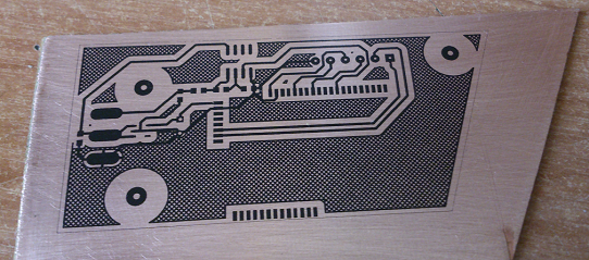
In addition to the module, it includes an opamp amplifier, a 5 V - 3.3 V converter for powering the JN5148 and a programming connector. Next, we make the board: iron, grass, drill, pound, solder.

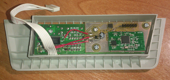
We install the board into place and start coding. By the way, the fact that the control board is disconnected from the power board turned out to be very convenient. It is enough to submit +5 V to it and it can work completely autonomously, so I installed it in the convector after the system was fully debugged.
Programming
Experimentally, I removed the dependence of the temperature measured by the convector on the voltage at the input of the ADC.
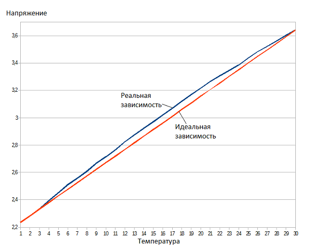
It can be seen that in the middle of the range the difference between the real and ideal characteristics is about 1 degree, so I decided to write the corresponding DAC codes to the array and depending on the temperature, take the necessary code from the array and send the DAC.
As a basis for programming, I used a Jennic template - JN-AN-1123-ZBPro-Application-Template, which can be downloaded here . It implements all the basic functionality of the ZigBee network, which works on the basis of the operating system JenOS, developed by Jennic for its microcontrollers. To whom it is interesting, they can download the template and see, but I will give here only the most important code.
This system presents all types of ZigBee network devices: a coordinator (convector), a router (USB whistle) and a sleeping terminal (sensor). Let's start with the simplest - with a USB whistle. He is committed to scanning UART for the appearance of a byte from the computer and sends the received byte to the coordinator.
The scan function is an operating system task that runs once every 50 ms. It checks whether the command has come and issues all incoming commands to the message queue, which is processed by the main task.
OS_TASK(APP_CommandScan) { APP_tsEvent sCommandEvent; int16 word; // word=i16Serial_RxChar(E_AHI_UART_0); // if(word != -1) { // sCommandEvent.eType = APP_E_EVENT_COMMAND; sCommandEvent.sCommand.u8Value = (uint8)word; OS_ePostMessage(APP_CommandEvent, &sCommandEvent); } // OS_eContinueSWTimer(APP_tmrCommandScan, APP_TIME_MS(50), NULL); } In the main loop, all incoming commands are sent to the coordinator.
// if (APP_E_EVENT_COMMAND == sAppEvent.eType) { // APDU PRIVATE PDUM_thAPduInstance s_hAPduInst = PDUM_INVALID_HANDLE; // APDU s_hAPduInst = PDUM_hAPduAllocateAPduInstance(apduCommand); // APDU PDUM_u16APduInstanceWriteNBO(s_hAPduInst, 0, // "b", // , (b) sAppEvent.sCommand.u8Value); // APDU 1 PDUM_eAPduInstanceSetPayloadSize(s_hAPduInst, 1); // , , u8Status = ZPS_eAplAfUnicastDataReq(s_hAPduInst, MYPROFILE_MYCLUSTER_CLUSTER_ID, USBSTICK_MYENDPOINT_ENDPOINT, THERMOSTAT_MYENDPOINT_ENDPOINT, 0x0000, // ( ) ZPS_E_APL_AF_UNSECURE, 0, &u8SeqNum); } The temperature sensor wakes up once per second (the time, of course, is adjusted), measures the temperature and voltage of the battery, sends everything to the convector, and then falls asleep again.
PRIVATE void vSendSensorData() { uint8 u8Status; uint8 u8SeqNum; // SensorData NewSensorData; // NewSensorData.TempValue = TempMeasurement(); NewSensorData.BattValue = BatVoltageMeasurment(); // // , uint32 MacH, MacL; MacH = MacAddr.u32H; MacL = MacAddr.u32L; // APDU PRIVATE PDUM_thAPduInstance s_hAPduInst = PDUM_INVALID_HANDLE; // APDU s_hAPduInst = PDUM_hAPduAllocateAPduInstance(apduTemperature); // APDU PDUM_u16APduInstanceWriteNBO( s_hAPduInst, 0, // "wwbh", // ( // 32- (ww) // 8- (b) 16- (h) MacH, MacL, NewSensorData.TempValue, NewSensorData.BattValue); // 11 PDUM_eAPduInstanceSetPayloadSize(s_hAPduInst, 11); // u8Status = ZPS_eAplAfBroadcastDataReq(s_hAPduInst, MYPROFILE_TEMPERATURE_CLUSTER_ID, TEMPSENSOR_TEMPSENSORENDPOINT_ENDPOINT, 0xFF, ZPS_E_BROADCAST_ZC_ZR, ZPS_E_APL_AF_UNSECURE, 0 , &u8SeqNum); } The coordinator, in turn, determines from whom the data came from and if it is temperature, then sets the corresponding voltage at the DAC output, and if it is a command from the computer, it sends pulses to the temperature setting buttons (emulates pressing).
Temperature setting function:
void SetTemp(int8 temp) { //, if(temp > 33) temp = 33; else if(temp < 0) temp = 0; // , vAHI_DacOutput(E_AHI_AP_DAC_1, temp_levels[temp]); } Receive data:
// if(MYPROFILE_TEMPERATURE_CLUSTER_ID == sStackEvent.uEvent.sApsDataIndEvent.u16ClusterId) { // PDUM_u16APduInstanceReadNBO(sStackEvent.uEvent.sApsDataIndEvent.hAPduInst, 8, "bh", &ReceivedTempSensorData); // SetTemp(ReceivedTempSensorData.TempValue); } else // USB { // PDUM_u16APduInstanceReadNBO(sStackEvent.uEvent.sApsDataIndEvent.hAPduInst, 0, "b", &Command); // , if(Command== '+') { vAHI_DioSetOutput(0, (1 << PLUS)); vDelay(50); vAHI_DioSetOutput((1 << PLUS), 0); } if(Command== '-') { vAHI_DioSetOutput(0, (1 << MINUS)); vDelay(50); vAHI_DioSetOutput((1 << MINUS), 0); } } And finally, the video of the system:
Useful links:
Description of the operating system JenOS
ZigBee Pro Stack Description
Description of functions for working with JN5148 peripherals
Archive with the project
Schema Archive
And yet, the article was published on May 7, so that everyone with the day of Radio!
Source: https://habr.com/ru/post/222085/
All Articles