Programming and JTAG debugging of the Atmega16 microcontroller in the C language in the IAR environment, part 1
Introduction
In my opinion, in order to quickly learn how to program almost any microcontroller existing in the world, you need to master the C language and use JTAG debugging, of course, besides studying technical documentation. I will explain my thought. C compilers exist for almost all existing microcontrollers. Therefore, language C has long established itself as a cross-platform assembler. His knowledge frees him from the need to learn assembler commands for each new microcontroller family. JTAG debugging, in turn, provides not only the possibility of in-circuit error detection, but also helps to study the microcontroller from the inside. I think that the fact that when simply programming without debugging even simple microcontrollers, we approach the study of the system as a black box with inputs and outputs is obvious to everyone. This approach, especially at the initial stage, makes learning difficult. On the other hand, the JTAG patch allows you to climb inside, to see how the program is executed step by step, to see what is happening in memory and registers, to start the excitement to breakpoints, to perform a disassembled version of the program. This feature allows you to significantly speed up learning.
Microcontrollers such as AVR, STM8, MSP430, AVR32, STM32, EFM32, Renesas RX have C compilers and the ability to debug using the JTAG interface. A single cross-platform environment for these many other microcontrollers is the Embedded Workbench. Although the medium and paid, but it is possible to use the 30-day free version or a version with a limit on the size of the code. For the initial study of the new family of the month may be quite enough. After that, you can form your own opinion about the family and decide to continue working with it on free tools, or for small projects use the version limited in code size. For large commercial products, you can purchase this medium.
')
I also think that it is better to start learning from the AVR, STM8, MSP430 families. The operation of these microcontrollers is easier to understand, because they have a relatively simple command system, a small number of processor registers and peripherals. It is better to start by writing simple examples, gradually moving to writing your libraries. All this is well covered by the head. For the first acquaintance it is very successful.
For the examples discussed below, I chose AVR because it is the most popular family in the microcontroller world. I think that it is easier to start with it, but you should not limit it to them.
Choosing a JTAG Debugger
For intracircuit debugging of programs written in C, we need a JTAG debugger for AVR microcontrollers. The most affordable and easy to manufacture clones are branded debugger AVR JTAGICE. Such a clone can be ordered at a low price with eBay . Quality is here, like a lottery.
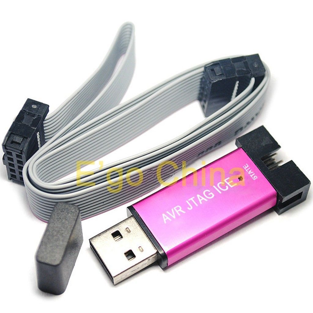
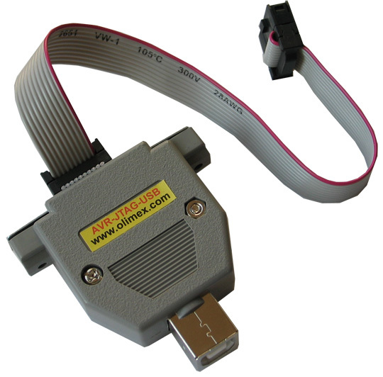
Also, clones are produced, for example, by Olimex . There is a classic version that is connected to the computer via the COM port and a newer version , where the connection is made via the USB interface.
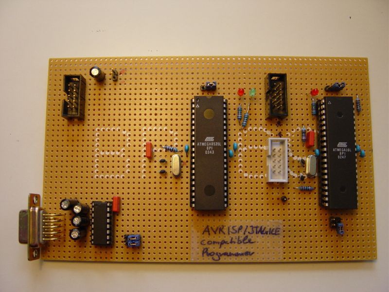
In the personal production of such a clone, if you can not make your PCB, you can use only DIP-components, which simplifies installation. An early version of Evertool , which contains the JTAGICE clone, was made that way.
 ]
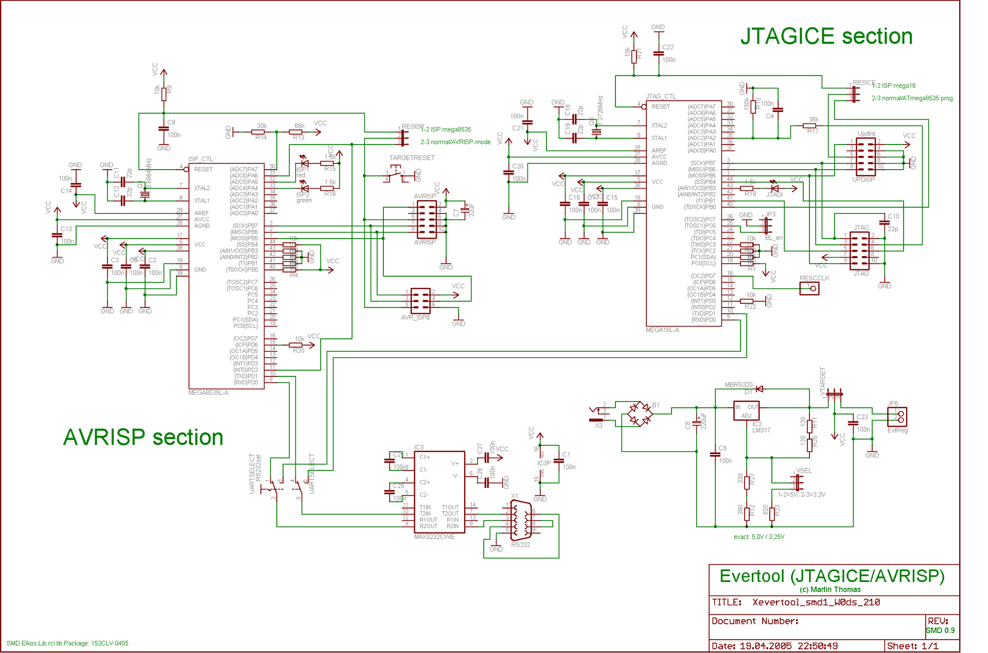
]At the core of most JTAGICE clones is the diagram shown in the image below. More precisely, the part called the JTAGICE section. The core of the debugger is the Atmega16L microcontroller. If we want to get the JTAGICE clone connected via USB, then we change the MAX3232 level conversion chip to an FTDI FT232 chip . However, FT232 in the DIP-package is not released, and the prices for DIP-modules with this chip are quite high. Therefore, you cannot get off with a single circuit board and DIP-components. You will have to either, as an option, solder the FT232 with thin wires to the breadboard, or bleach with a ferric chloride single-layer PCB with a normal footprint.
The firmware can be found in the installation folder of AVR Studio 4 or downloaded here .
The disadvantage of the JTAGICE clones described above is that they are not supported in AVR Studio 6 . However, in the old version of AVR Studio 4 and the old and new versions of IAR for AVR, these clones are perfectly supported.
To debug C code examples written below, I used a clone made according to this scheme. The MAX3232 chip in it is replaced with an ADM3202, which does not change the essence.
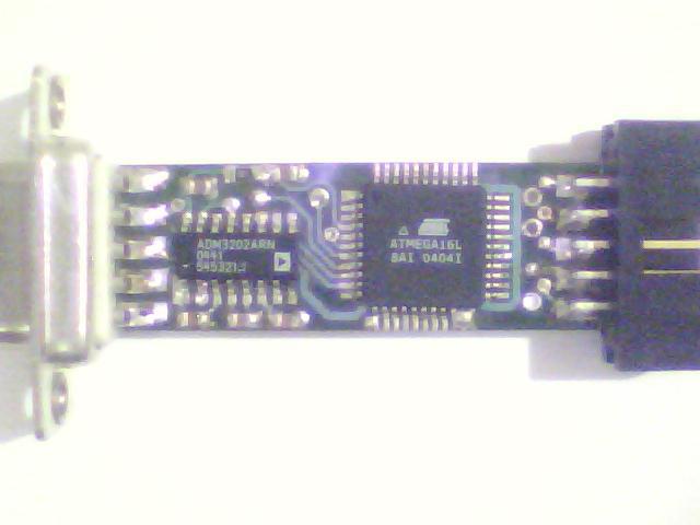
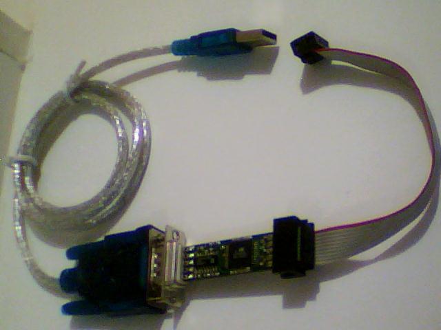
This JTAGICE clone was inherited by me. I found a box with electronic debris at work. It did not work, and I decided to reflash it. Why did you need to make a special adapter, because, as seen in the photo, the AVR ISP connector for programming the Atmega16L is not displayed to reduce the size. After the firmware, JTAGICE earned and gained an “afterlife” life.
Now that the COM port has become unfashionable, I did not give up the “old friend” and bought a USB to RS-232 converter cable .
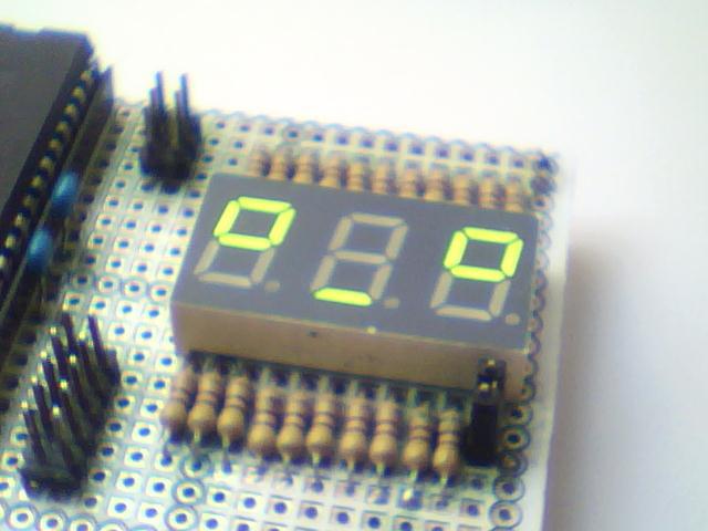
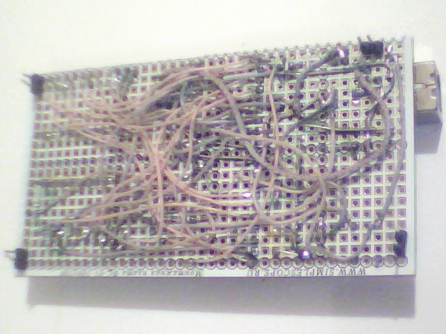
Debug board
As a debug board, I will use a digital thermometer assembled by me on a breadboard. The board is powered by USB, the core is an Atmega16 microcontroller in a DIP package. The microcontroller is clocked from a 16 MHz quartz resonator and tied with the minimum necessary set of passive components (22 pF capacitors for quartz, a 10 kΩ resistor per pull-up line for the power supply, 0.1 microfarads for power supply). For programming and debugging the microcontroller, two standard six-pin AVR ISP and ten-pin AVR JTAG connectors are derived. The board has an analog temperature sensor, a static seven-segment indicator for three digits, an additional LED. The indicator LED and indicator segments are connected to the microcontroller via current-limiting resistors of 500 Ohms each. Each of the three seven-segment indicators is connected to pins zero through sixth of one of ports A, B and D. The indicator LED is connected to the 7th output of port D. The output of the analog sensor is connected to the 7th output of port A (7th channel of the built-in ADC ).
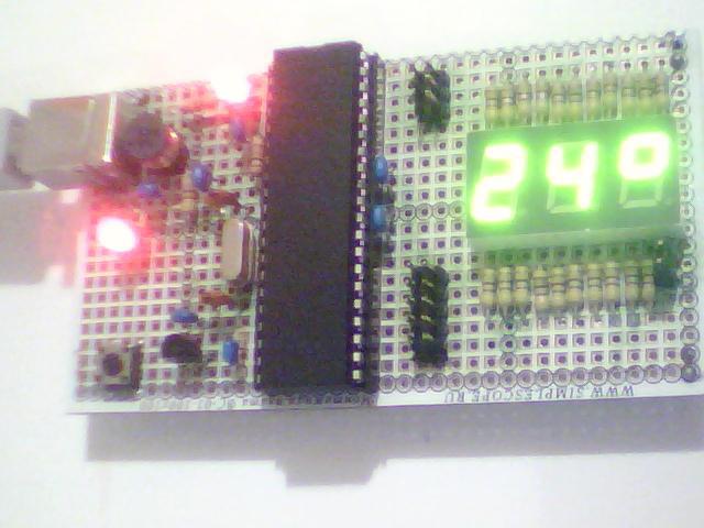
All elements were soldered with MGTF wire.
IAR development environment
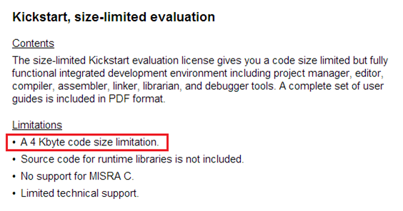
For writing and debugging programs we will use the IAR Embedded Workbench for Atmel AVR environment, namely, its free version with a code limit of 4 KB. For small projects in C language for microcontrollers of the AVR family, this is quite enough.
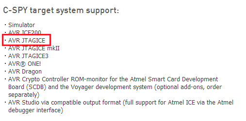
Go here and read, that provides the latest version of IAR for AVR at the current time. The JTAGICE debugger mentioned above, as before, is supported.
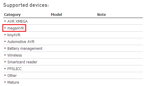
In the list of supported families there is megaAVR.
After making sure that our JTAG debugger and debugging motherboard go, download IAR .
The installer allows you to register with the Kickstart license.
After installation, in order to register IAR, you will have to fill in the registration form.
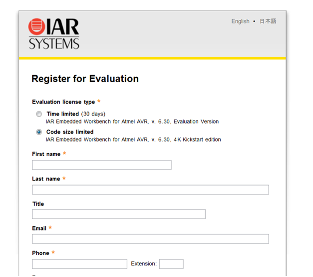
After filling in the questionnaire, the key will come to your mail, by entering which, we will receive a free registered Kickstart-version not limited in time.

Create an empty project for our tasks. We choose the C language and the AVR Studio 4 compatible output option, in case you have to stitch the output hex file with AVR Studio 4.
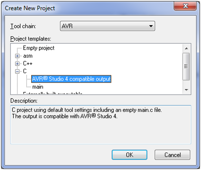
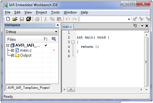
After selecting a language, an empty, almost empty source file will appear in front of us.
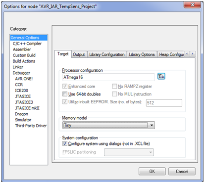
Let us turn to the settings of our project. Since we will write programs for Atmega16, we will select this microcontroller in the column Processor configuration.
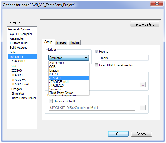
In the Debugger menu item, select JTAGICE.
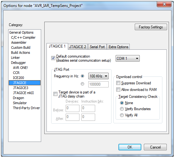
In the Debugger-> JTAGICE menu item, select the COM port number to which the debugger is connected.
For correct operation of the definitions of the significant bits of the microcontroller peripherals registers in the environment libraries it is also necessary to put
tick Enable bit definitions in I / O-Include files in the menu item General Options-> System.

Programming and debugging
Before starting the description of examples, it is necessary to explain some features of the IAR environment. In the iom16.h header file, which contains the definitions of register addresses for the Atmega16, there are macros that allow you to access specific bits of the internal peripheral registers, as follows:
... * Examples of how to use the expanded result: * TCCR2 |= (1<<5); * or if ENABLE_BIT_DEFINITIONS is defined * TCCR2 |= (1<<COM21); * or like this: * TCCR2_Bit5 = 1; * or like this: * TCCR2_COM21 = 1; ***************************************************************************/ In fact, you can use any of these options. And the choice here, in essence, consists in the convenience of using a particular variant and the simplicity of the subsequent understanding of what is written.
In the IAR environment, it is possible to use the built-in delay function __delay_cycles (x), where x is the delay time in cycles. For our case, the delay per clock is 1/16000000 = 62.5 ns.
Now that we know these two points, we can move to the first example, where the LED just blinks, using an exclusive or.
/* */ #include <ioavr.h> #include <intrinsics.h> /* */ // #define F_CPU 16000000 /* */ // #define DELAY_US(us) __delay_cycles((F_CPU / 1000000) * (us)); // #define DELAY_MS(ms) __delay_cycles((F_CPU / 1000) * (ms)); /* */ // void main( void ) { // // // 7- D DDRD_DDD7 = 1; // 7- D "0" PORTD_PORTD7 = 0; // for(;;) { // 7- D "0" "1" "1" "0" // PORTD_PORTD7 ^= 1; // DELAY_MS(1000); }//end for } To simplify the formation of the delay of the required duration, the DELAY_US (us) and DELAY_MS (ms) delay macrofunctions are created, which allow you to set the delay not in ticks, but in microseconds and milliseconds right away. Then we move on to the main function of the program main (), which we find ourselves after turning on the microcontroller or after resetting. It is logical that the first thing we need to do after switching on is to set up the peripheral blocks necessary for operation in our case, this is only one output of port D. To configure it for output, set the DDD7 bit of the DDRD data direction register to one. In order to set “1” on foot (5 V), you need to set the PORTD7 bit in the PORTD data register, in order to set “0” (ground) on the foot, you need to reset the PORTD7 bit. In the datasheet you can read more about this.
To set and write bits of the DDRD and PORTD control registers, it is undesirable to use just write (DDRD = 0x01, DDRD = 0x00) without bitwise disjunction and conjunction (DDRD | = 0x01, DDRD & = ~ 0x01, DDRD | = (1 << 0), DDRD & = ~ (1 << 0)), because if it is to erase the remaining bits in the register that were set before this operation. It is important to understand.
After tuning, we move to the main infinite loop for (;;), in which, as a rule, the main logic of the program is executed. Such a model of the microcontroller program implementation is called a system with a super-cycle. This infinite loop pauses at the time of processing interrupts of peripheral blocks and when switching to the low-power mode, and stops only when the microcontroller is reset and turned off.
In the main infinite loop, there is a constant switching of “0” to “1”, then “1” to “0”, using a bitwise exclusive or operation. This happens with a delay of one second, which is provided by the DELAY_MS (ms) macro function.
We will now load and debug this example using JTAGICE. To do this, click on the menu item Project-> Download and Debug or press the key combination Ctrl + D or the icon with the red triangle, then, if there are no syntax errors in the code, we will switch to debugging mode, in which step-by-step Step commands are available to us Over, Step Into, Step Out, Next Statement, Go, Reset. In addition, it is possible to use breakpoints. This allows you to step through the program and see what happens at each step in the processor registers and DDRD and PORTD registers of port D, start execution, then stop, start to a breakpoint. All this gives not only an error search tool, but also helps to better understand the microcontroller's operation. Learn to work with him faster.
The second example is also the flashing of the LED, but with the use of additional macro functions.
/* */ #include <ioavr.h> #include <intrinsics.h> /* */ // #define F_CPU 16000000 // #define DELAY_TIME 1000 // // #define LED_DDR DDRD #define LED_PORT PORTD #define LED_PIN DDD7 /* */ // #define LED_INIT() ( LED_DDR |= (1<<LED_PIN) ); // #define LED_LOW() ( LED_PORT &=~ (1<<LED_PIN) ); // #define LED_HIGH() ( LED_PORT |= (1<<LED_PIN) ); // #define LED_TOG() ( LED_PORT ^= (1<<LED_PIN) ); // #define DELAY_US(us) __delay_cycles((F_CPU / 1000000) * (us)); // #define DELAY_MS(ms) __delay_cycles((F_CPU / 1000) * (ms)); /* */ // void main( void ) { // // LED_INIT(); // LED_LOW(); // for(;;) { // LED_TOG(); // DELAY_MS(DELAY_TIME); }//end for } The macro-function approach provides convenience in two ways. The first is to provide improved code readability. The second is the simplification of possible fixes. Now, if the LED needs to be reconfigured to another output of another port, it is enough to change three definitions of LED_DDR, LED_PORT, LED_PIN, and not to make corrections throughout the text of the program. When writing libraries, this greatly simplifies life.
The third example is the implementation of LED blinking, using a state machine. The state machine is one of the implementation variants of the microcontroller firmware model, in which an infinite loop is divided into branches depending on the current state.
/* */ #include <ioavr.h> #include <intrinsics.h> /* */ // #define F_CPU 16000000 // #define DELAY_TIME_LF 1000 #define DELAY_TIME_AF 500 #define DELAY_TIME_HF 100 // #define LIMIT_CNT_LF 4 #define LIMIT_CNT_AF 8 #define LIMIT_CNT_HF 40 // #define UCHAR unsigned char // #define STATE_LOW_FREQ_BLINK 0 #define STATE_AVR_FREQ_BLINK 1 #define STATE_HIGH_FREQ_BLINK 2 // // #define LED_DDR DDRD #define LED_PORT PORTD #define LED_PIN DDD7 /* */ // #define LED_INIT() ( LED_DDR |= (1<<LED_PIN) ); // #define LED_LOW() ( LED_PORT &=~ (1<<LED_PIN) ); // #define LED_HIGH() ( LED_PORT |= (1<<LED_PIN) ); // #define LED_TOG() ( LED_PORT ^= (1<<LED_PIN) ); // #define DELAY_US(us) __delay_cycles((F_CPU / 1000000) * (us)); // #define DELAY_MS(ms) __delay_cycles((F_CPU / 1000) * (ms)); /* */ // UCHAR curr_state = STATE_LOW_FREQ_BLINK; // // UCHAR state_cnt = 0; /* */ // void main( void ) { // // LED_INIT(); // LED_LOW(); // for(;;) { // switch(curr_state) { // case STATE_LOW_FREQ_BLINK: // LED_TOG(); // DELAY_MS(DELAY_TIME_LF); // state_cnt++; // //, if (state_cnt==LIMIT_CNT_LF) { curr_state = STATE_AVR_FREQ_BLINK; // state_cnt = 0; }//end if break; // case STATE_AVR_FREQ_BLINK: // LED_TOG(); // DELAY_MS(DELAY_TIME_AF); // state_cnt++; // //, if (state_cnt==LIMIT_CNT_AF) { curr_state = STATE_HIGH_FREQ_BLINK; // state_cnt = 0; }//end if break; // case STATE_HIGH_FREQ_BLINK: // LED_TOG(); // DELAY_MS(DELAY_TIME_HF); // state_cnt++; // //, if (state_cnt==LIMIT_CNT_HF) { curr_state = STATE_LOW_FREQ_BLINK; // state_cnt = 0; }//end if break; } }//end for } In our example, there are three states STATE_LOW_FREQ_BLINK, STATE_AVR_FREQ_BLINK, STATE_HIGH_FREQ_BLINK, which correspond to the flashing LED with low frequency, middle frequency and high frequency, respectively. Each state has its own delay value DELAY_TIME_LF, DELAY_TIME_AF, DELAY_TIME_HF, performed in each state pass. The same period of being in each state is provided by the LIMIT_CNT_LF, LIMIT_CNT_AF, LIMIT_CNT_HF definitions, which determine the number of switching-switches for each state. The switch statement switches between the states according to the current value of the curr_state variable. The state_cnt variable is incremented in each state pass until the switching limit is reached in the state. The if statement determines if the switching limit is reached. If the limit is reached, a transition to the next state occurs, the state_cnt pass counter is reset.
Under debugging now, besides the one already described above, you can view the value of the curr_state and state_cnt variables in View-> Watch.
The fourth example is devoted to working with an eight-bit timer (TIMER0) of a micro-controller. In this example, one of the segments of a seven-segment indicator connected to the 6th pin of port D is used as the second LED.
/* */ #include <ioavr.h> #include <intrinsics.h> #include <ina90.h> /* */ // #define F_CPU 16000000 // #define TCNT0_VALUE 99 // #define T0_TICK_CNT_LIMIT 100 // #define UINT unsigned int /* */ // #define DELAY_US(us) __delay_cycles((F_CPU / 1000000) * (us)); // #define DELAY_MS(ms) __delay_cycles((F_CPU / 1000) * (ms)); /* */ // T0 UINT T0_tick_cnt=0; /* */ // void main( void ) { // // // 6- D DDRD_DDD6 = 1; // 6- D "0" PORTD_PORTD6 = 0; // // 7- D DDRD_DDD7 = 1; // 7- D "0" PORTD_PORTD7 = 0; // ( Normal) TCCR0_CS02=1;// 16 000 000 TCCR0_CS01=0;// 16 000 000 / 1024 = 15 625 TCCR0_CS00=1;// 1 / 15 625 = 0,000064 =64 TCNT0 = TCNT0_VALUE; // 156 * 0,000064 c = 0,009984 c (10 ) // 255-156 = 99 TIMSK_TOIE0=1; // // _SEI(); // for(;;) { // _NOP(); // 6- D "0" "1" "1" "0" // PORTD_PORTD6 ^= 1; // DELAY_MS(500); }//end for } /* T0 */ #pragma vector=TIMER0_OVF_vect __interrupt void ISR_TickTimer(void) { // _NOP(); // T0 T0_tick_cnt++; // 1 if (T0_tick_cnt >= T0_TICK_CNT_LIMIT) { // T0 T0_tick_cnt=0; // 7- D "0" "1" "1" "0" // PORTD_PORTD7 ^= 1; } // // TCNT0=TCNT0_VALUE; }//end func In this example, in the function main (), after setting the LEDs, the zero timer is set, which consists in setting the bits in the control register TCCRO. Since we will use the timer mode Normal, then the bits WGM00 and WGM01 should be zero. The initial value and so is zero, so just do not touch them. Bits CS00, S01, S02 set so as to get the maximum divider (1024) clocking frequency of 16 MHz.
After dividing, we get the frequency of the timer 15625 Hz, which corresponds to a tick of 64 μs. We will get the closest to 10 ms if we multiply the tick by 156 (156 * 0.000064 c = 0.009984 c = 10 ms). Therefore, to receive the generation of an interrupt for processing an overflow event every 10 ms, it is necessary to load register 99 (255-156 = 99) into the counting TCNT0. Since Since the timer starts counting from 99, and the interrupt is generated when it reaches 255, then we will get a path of 156 ticks.
Further in the example, in order to generate a zero timer overflow interrupt, the TOIE0 bit in the TIMSK interrupt masking register is set. Then we do the global resolution of all masked interrupts with the _SEI () macro function.
Definitions of all interrupt vectors are in the iom16.h header file:
/*==============================*/ /* Interrupt Vector Definitions */ /*==============================*/ /* NB! vectors are specified as byte addresses */ #define RESET_vect (0x00) #define INT0_vect (0x04) #define INT1_vect (0x08) #define TIMER2_COMP_vect (0x0C) #define TIMER2_OVF_vect (0x10) #define TIMER1_CAPT_vect (0x14) #define TIMER1_COMPA_vect (0x18) #define TIMER1_COMPB_vect (0x1C) #define TIMER1_OVF_vect (0x20) #define TIMER0_OVF_vect (0x24) #define SPI_STC_vect (0x28) #define USART_RXC_vect (0x2C) #define USART_UDRE_vect (0x30) #define USART_TXC_vect (0x34) #define ADC_vect (0x38) #define EE_RDY_vect (0x3C) #define ANA_COMP_vect (0x40) #define TWI_vect (0x44) #define INT2_vect (0x48) #define TIMER0_COMP_vect (0x4C) #define SPM_RDY_vect (0x50) The logic of the program is the system with a super-cycle already described in the first example, where a quasi-parallel operation of the main loop and interrupt handler is provided. In the main cycle, the sixth output of port D is switched with a period of 500 ms. The main loop is interrupted every 10 ms to process a zero timer overflow interrupt. Processing is performed using the handler function ISR_TickTimer (), which is called on this event. In this function, by incrementing the variable T0_tick_cnt, 10 millisecond ticks are counted. When the variable T0_tick_cnt reaches 100 (that is, one second has passed), this event is determined by the if statement in the handler. After that, the variable T0_tick_cnt switches the output of port 7 of port D, which ensures the second LED flashes with a period of 1000 ms.
When debugging this example, you can put a breakpoint both in the main loop and in the interrupt handler.
The fifth example is, according to the logic of work, the previous example, but using macro functions.
/* */ #include <ioavr.h> #include <intrinsics.h> #include <ina90.h> /* */ // #define F_CPU 16000000 // #define DELAY_TIME 500 // // #define LED1_DDR DDRD #define LED1_PORT PORTD #define LED1_PIN DDD7 // // #define LED2_DDR DDRD #define LED2_PORT PORTD #define LED2_PIN DDD6 // #define F_CPU_DIV_1 (0<<CS02)|(0<<CS01)|(1<<CS00) #define F_CPU_DIV_8 (0<<CS02)|(1<<CS01)|(0<<CS00) #define F_CPU_DIV_64 (0<<CS02)|(1<<CS01)|(1<<CS00) #define F_CPU_DIV_256 (1<<CS02)|(0<<CS01)|(0<<CS00) #define F_CPU_DIV_1024 (1<<CS02)|(0<<CS01)|(1<<CS00) // #define TCNT0_VALUE 99 // #define T0_TICK_CNT_LIMIT 100 // #define UINT unsigned int /* */ // #define LED1_INIT() ( LED1_DDR |= (1<<LED1_PIN) ); // #define LED1_LOW() ( LED1_PORT &=~ (1<<LED1_PIN) ); // #define LED1_HIGH() ( LED1_PORT |= (1<<LED1_PIN) ); // #define LED1_TOG() ( LED1_PORT ^= (1<<LED1_PIN) ); // #define LED2_INIT() ( LED2_DDR |= (1<<LED2_PIN) ); // #define LED2_LOW() ( LED2_PORT &=~ (1<<LED2_PIN) ); // #define LED2_HIGH() ( LED2_PORT |= (1<<LED2_PIN) ); // #define LED2_TOG() ( LED2_PORT ^= (1<<LED2_PIN) ); // #define TIMER0_SET_CLK_DIV(x) ( TCCR0 |= x ); // #define TIMER0_SET_CNT(x) ( TCNT0 = x ); // #define TIMER0_OVF_INT_ON() ( TIMSK|=(1<<TOIE0) ); // #define DELAY_US(us) __delay_cycles((F_CPU / 1000000) * (us)); // #define DELAY_MS(ms) __delay_cycles((F_CPU / 1000) * (ms)); /* */ // T0 UINT T0_tick_cnt=0; /* */ // void main( void ) { // // LED1_INIT(); LED2_INIT(); // LED1_LOW(); LED2_LOW(); // ( Normal) TIMER0_SET_CLK_DIV(F_CPU_DIV_1024);// 16 000 000 // 16 000 000 / 1024 = 15 625 // 1 / 15 625 = 0,000064 =64 TIMER0_SET_CNT(TCNT0_VALUE); // 156 * 0,000064 c = 0,009984 c (10 ) // 255-156 = 99 TIMER0_OVF_INT_ON(); // // _SEI(); // for(;;) { // _NOP(); // LED1_TOG(); // DELAY_MS(DELAY_TIME); }//end for } /* T0 */ #pragma vector=TIMER0_OVF_vect __interrupt void ISR_TickTimer(void) { // _NOP(); // T0 T0_tick_cnt++; // 1 if (T0_tick_cnt >= T0_TICK_CNT_LIMIT) { // T0 T0_tick_cnt=0; // LED2_TOG(); }//end for // // TIMER0_SET_CNT(TCNT0_VALUE); }//end func Shows the bits in the control register of the zero timer TCCRO, when configured, is carried out using the TIMER0_PET_CLK_DIV (x) macro function, whose argument x determines how much the clocking frequency is divided and is selected from the set of definitions F_CPU_DIV_1, F_CPU_DIV_8, F_CPU_DIV__IV, 41_FIV_1, F_CPU_DIV_8, F_CPU_DIV_F, and The initial value in the TCNT0 account register is written using the TIMER0_SET_CNT (x) macro function, where the argument x is the initial value itself (TCNT0_VALUE = 99 in our case). Setting the TOIE0 bit in the TIMSK interrupt masking register is done using the TIMER0_OVF_INT_ON () macro function.
All examples in the form of the IAR project can be downloaded here .
Conclusion
If this post is of interest, in the next part we will look at examples of working with the built-in ADC, seven-segment segments. After that, we will collect all the considered examples in a software project of a digital thermometer.
Addition
If there is a need to get a hex file of a program written in IAR, then it is not at all difficult to do. It is enough in the project settings on the Linker-> Output tab and on the Linker-> Extra Output tab to make the settings, as in the screenshots below. After that, if you rebuild the project by clicking Project-> Rebuild All in the subfolder of [project name] \ Debug \ Exe, you will be able to find the hex file. Which can be sewn with the AVR910 programmer, STK500 clone or any other available programmer.
Source: https://habr.com/ru/post/221719/
All Articles