Another smart outlet for another smart home
For many years I dreamed of creating a smart home, but each time I stopped the problem of the connection of modules (sockets, sensors and switches) with the center and among themselves. But progress does not stand still, more and more frequently encountered information about microcontrollers with built-in transceivers pushed me back to my old idea. In this post I will talk about how to create a "smart socket" (actually a surge protector), which is presented in the photo below.

Everything else is under the cut. Caution! A lot of pictures.
First, I must say that in the city in which I now live, there is a very big problem with electronic components (resistors of 5p. Each, but we have never heard of microcontrollers here). I have to order everything or ask my comrades to transfer me from more advanced places in this plan. I hope this information will explain possible questions about the use of certain components. This is not my first device and, thanks to the use of ready-made modules, the need to draw schemes has disappeared. I present only the scheme of the triac key.
')
I ordered wonderful modules with unsoldered nRF24LE1 from our beloved friends from heaven. About this microcontroller has already been written a lot on Habré ( here , and here , and here again), and it really helped at the start.
My modules, unlike most of those considered in Habré, are smaller in size and have PLS with a small step (by the way, the community can tell you how these pins are correctly named and where to get the mating part).

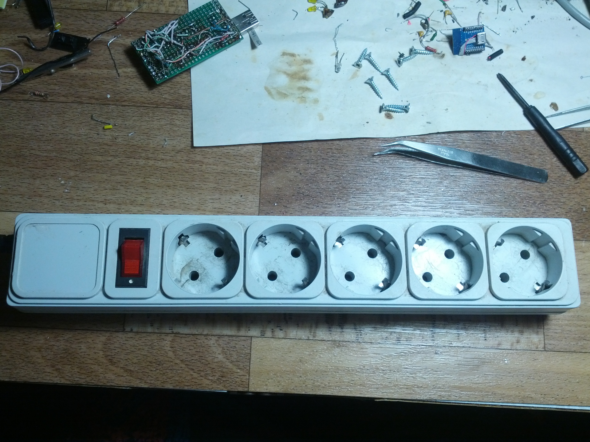
An ordinary, already tested by accountants and cleaners, asurge protector was chosen as the martyr of the modernized. I rubbed it as much as I could, but there is some tiredness from constant kicking with my legs.
Similarly, the simistors BTA16 (600v, 16A) and the opto-simistors MOC3063 were ordered from the Middle Kingdom. Partly was loose, partially bought.
So, fight!
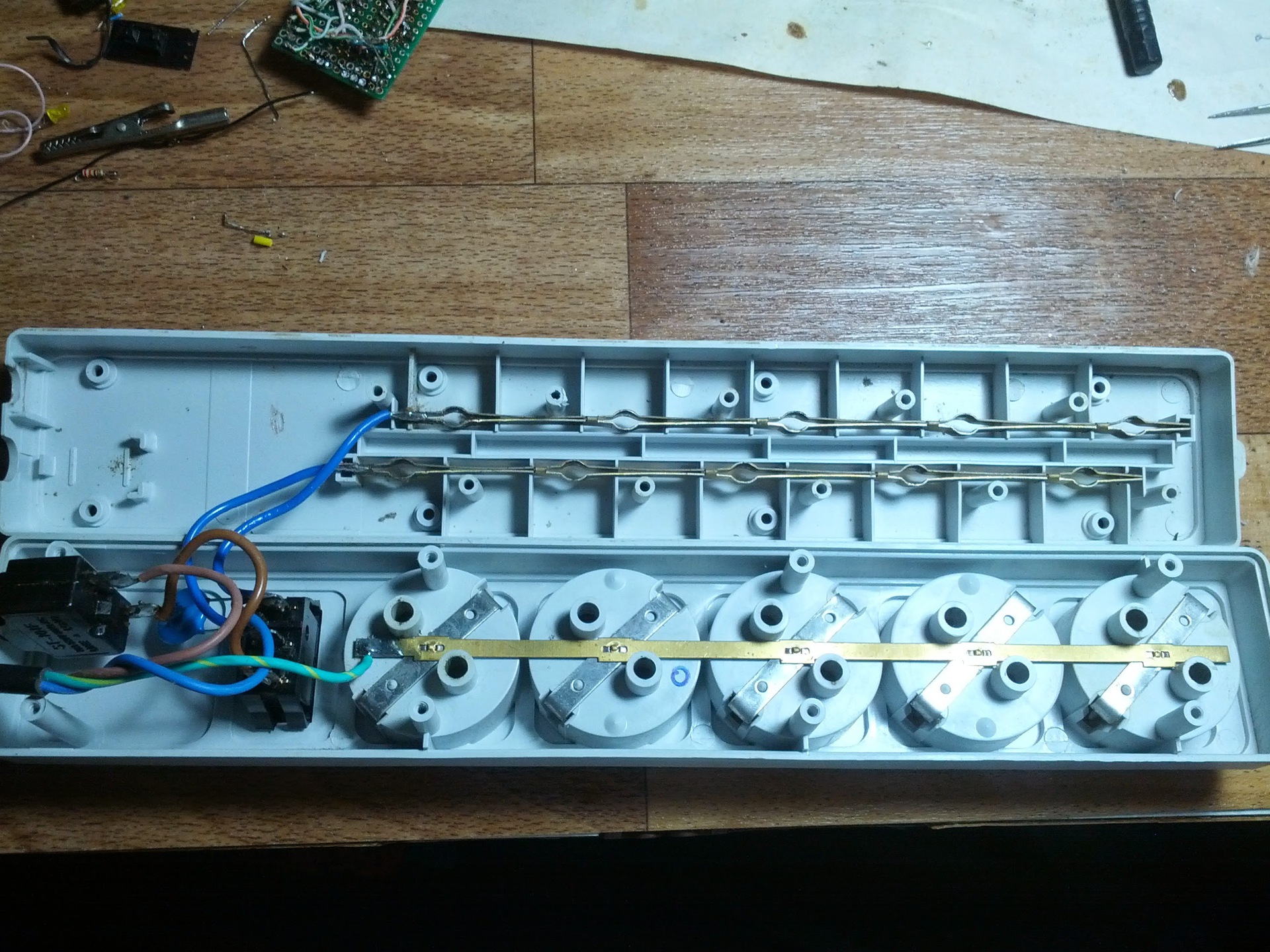
To begin with, I disassembled the power filter to understand if I had enough space.
Placeswagon and cart missing.
Next for the firmware nRF24LE1 decided to use the microUSB connector. There are enough contacts, but you need to pull up the PROG input to the power supply in order to switch the micron to the programming mode. I decided to do a simple jumper (which I had to make myself from heat shrinkage and wire).

Separate, great, thanks to the post from MaksMS , as well as to him personally. The article and the correspondence with him greatly helped to start programming the nrf24le1, as well as to get the radio part.
So, the module responds to requests from the programmer (using USB ASP), go to the management of the power unit. To control the triac decided to use the opto-triac MOC3063. This microcircuit completely separates the power part from the low-voltage one, but there is one nuance. The MOC3063 has a built-in 0-crossing (zero-cross) detector in the power supply network and sends an opening pulse to the triac itself, which in turn leads to the fact that we cannot dim the outlet, but I did not pursue this goal. The wiring diagram is below:
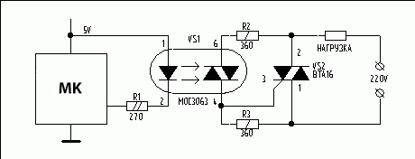
The scheme is simple, I think, no further explanation is necessary. The only retreat, instead of the limiting resistor, was a green LED that will signal when the opacistor is turned on.
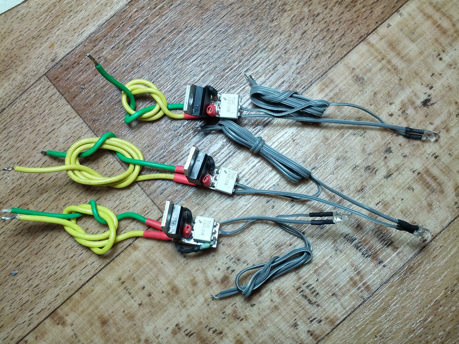
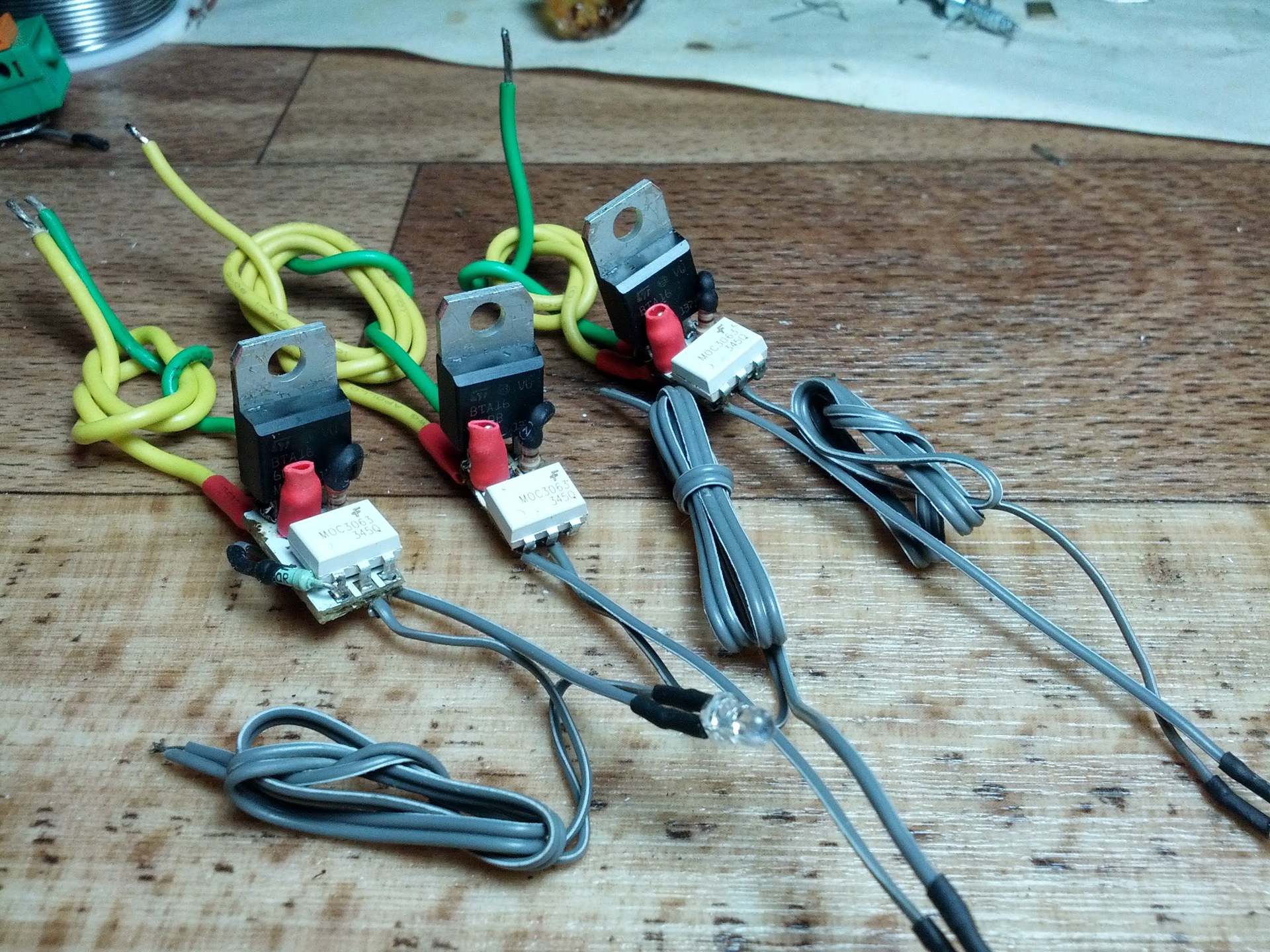
According to the scheme assembled, small modules for 5 outlets (only 3 in the photo):
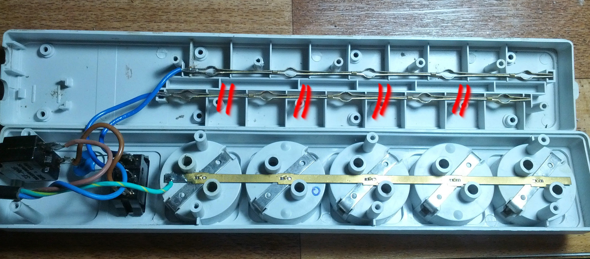
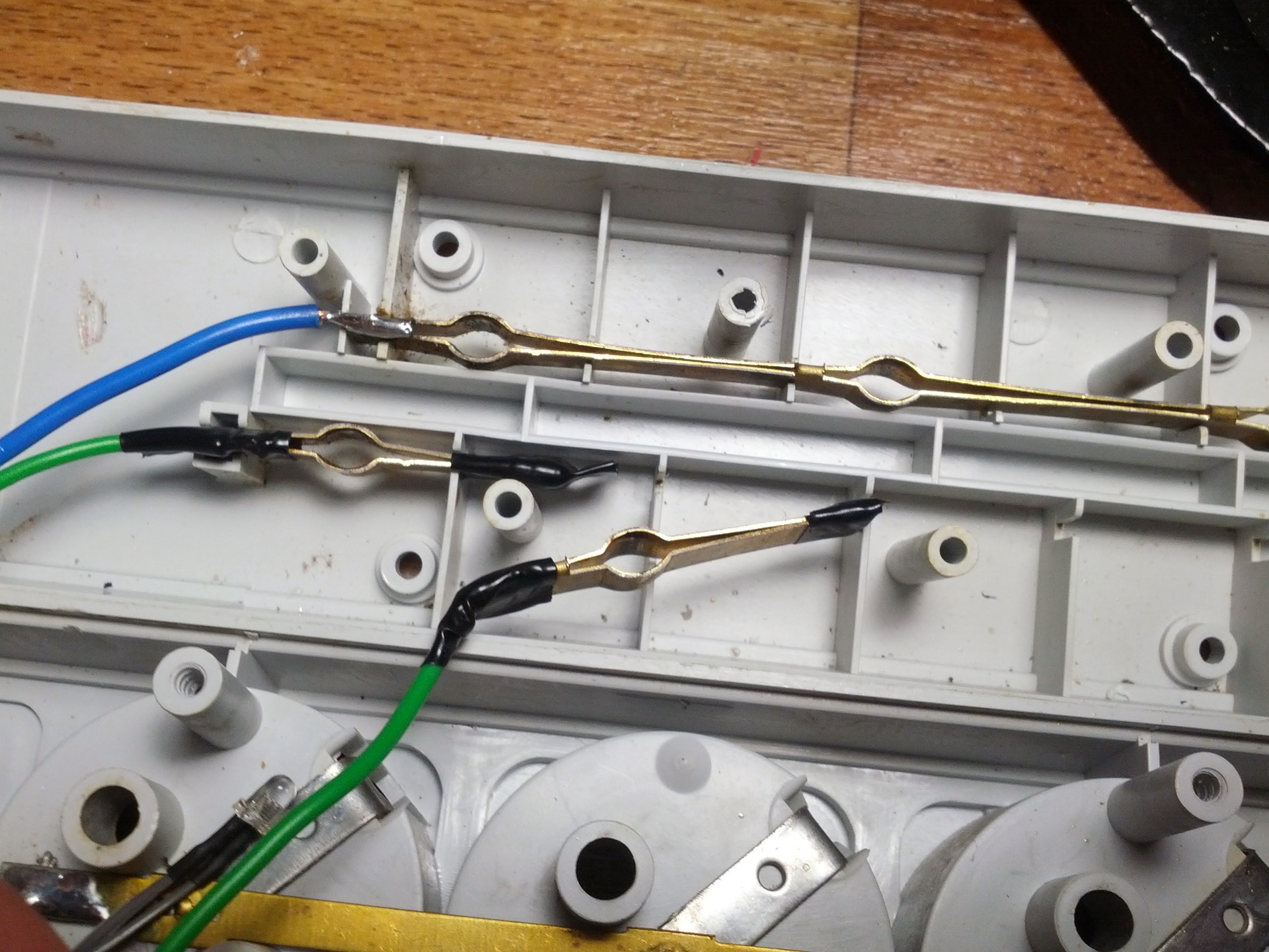
Further, one of the lines in the network filter was cut in the indicated places, and from the cut-out gaps made jumpers on the “non-bonded” ends, so that when the plug was turned on they would not be strongly bent.
Soldered the control outputs of the triac modules to the pins of the microcontroller module 0.2, 0.1, 0.0, 1.6, 1.5.
5 yellow LEDs soldered to pins 0.7, 1.0, 1.1, 1.2, 1.3. By pins 0.5, 0.6, I soldered green and red LEDs to indicate the operation of the module (command parsing, receiving or sending data).
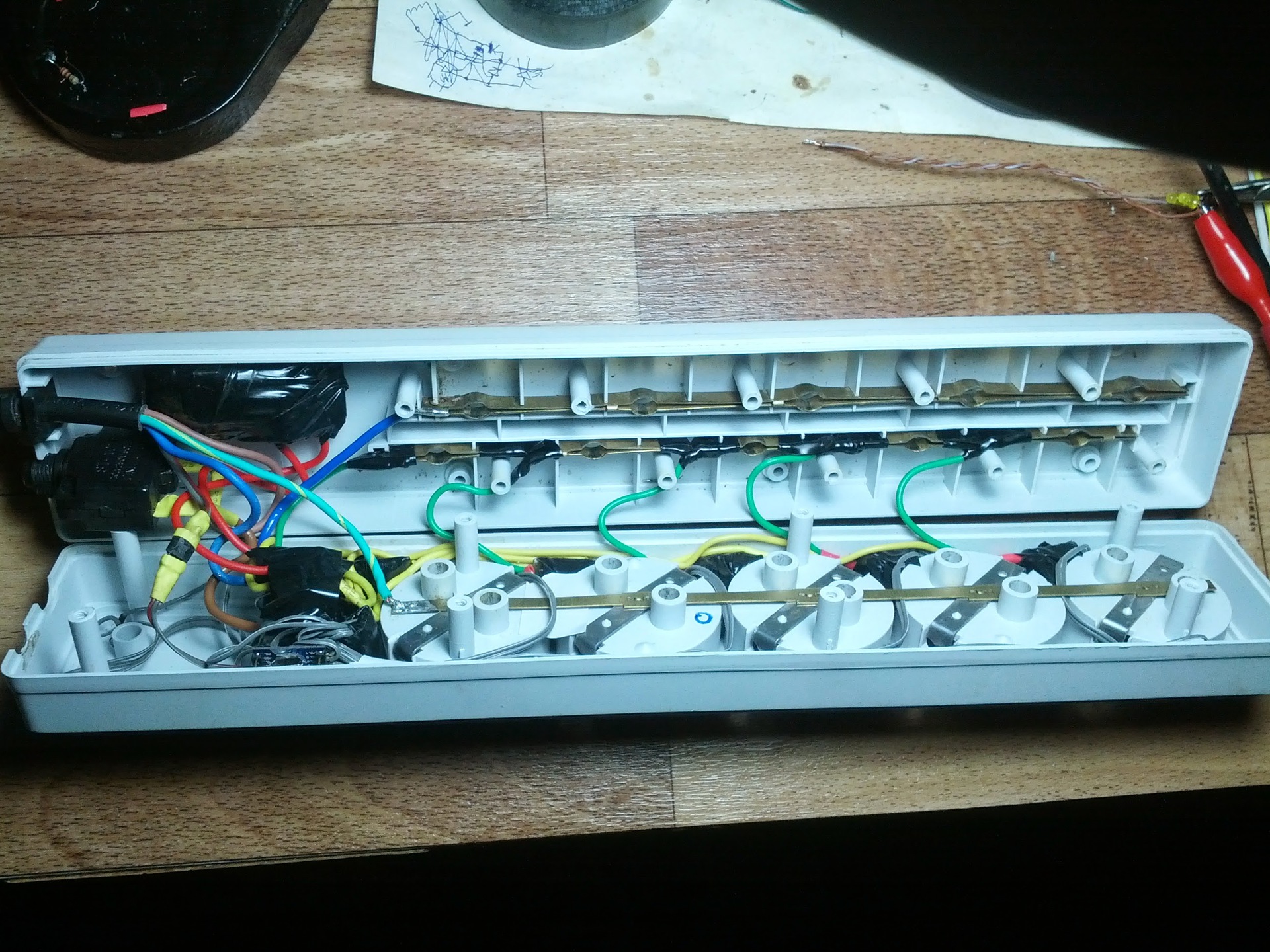
All this stuff is packaged in a network filter housing.
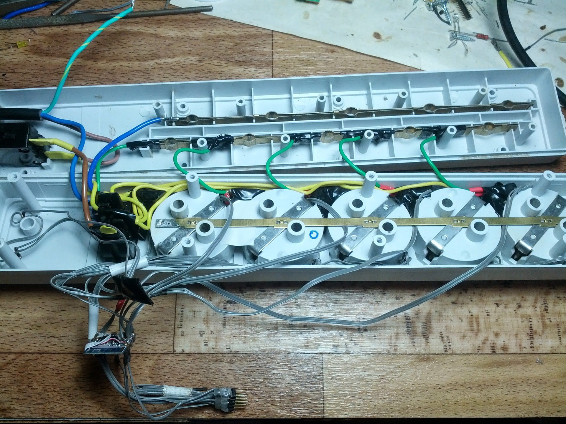
The triac modules fit perfectly in the gaps between the boxes for the plugs (in the photo they are green and gray wiring), under the modules there are green LEDs (in pre-drilled holes) in the opposite side from them, yellow LEDs are installed.
From the left in the middle are the ends of the two LEDs of the micron state.
Well, in the lower left corner you can see the radio itself with a hanging connector for programming.Wait, where is the vaunted microUSB !? At the time of the shooting, the microUSB cable that I had turned out to be too long and the programmer did not see the MK.
Further, the biggest problem of the whole event: food for the microcontroller. At first I wanted to make a capacitor power supply, but I did not find the necessary capacitors and a zener diode in the city, but there was no desire to order and wait. I decided to use the power supply from charging for some phone.

He suffered for a long time with a block that was on top (with a red stripe), but it turned out that his optocoupler had burned down, and the zener diode on the block was extremely hot. It was very dangerous to put such a thing, and I decided to use a block that is below (with a yellow stripe), although I had to leave one of the home devices without power.
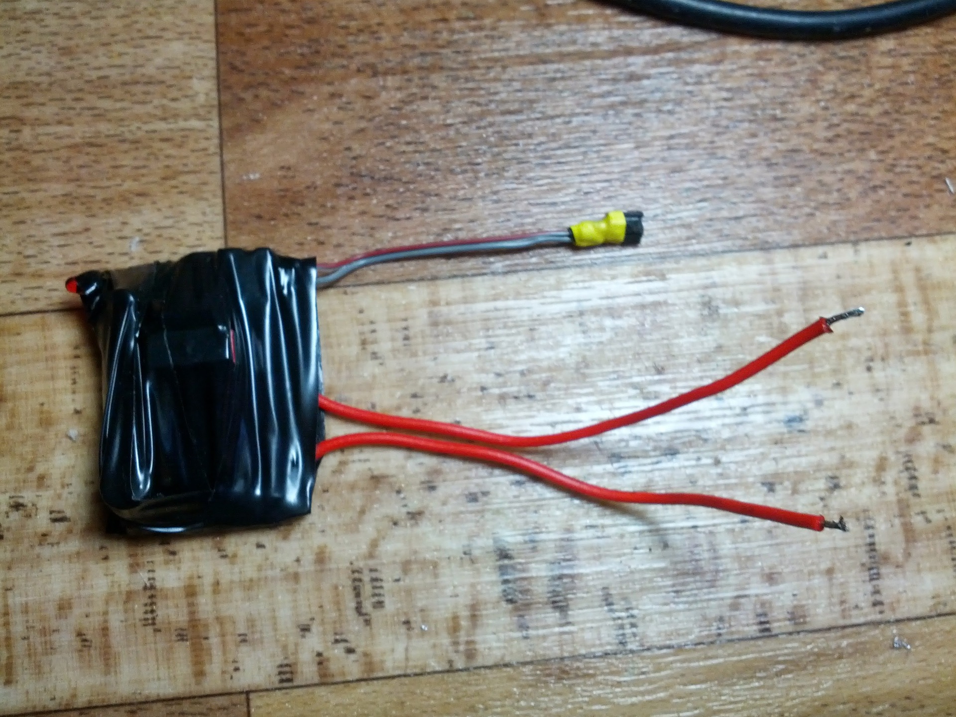
It is clear that the capacitor version would be much smaller, but the charging has a galvanic isolation, which allows in the future to bring a connector for programming outside the case.
However, the unit fits perfectly into the filter housing, and the whole structure has the following appearance:
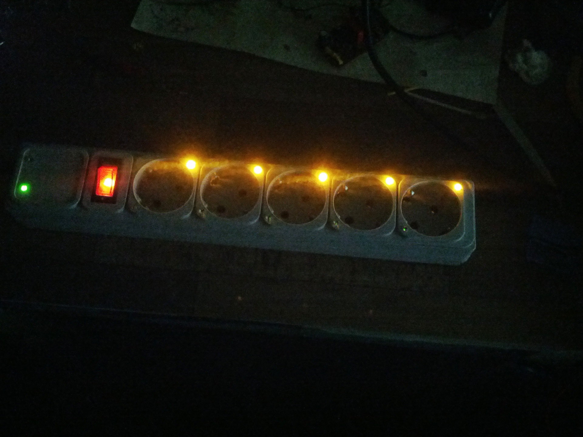
After assembly in working condition:
Unfortunately, I can not yet post the firmware, because it is very confused. It was written taking into account the work on the network with many devices, and there is a lot of superfluous in it. If the community is interestedand I finally get an invite, I will publish everything in the next post. It should be noted that there is no tricky algorithm there. It all comes down to simple jerking pins on / off. No shima and so on. Simple flashing of LEDs (power modules for MK - ordinary LEDs)
The principle of operation is as follows: when receiving a packet from the server, the module determines what should be done with the selected outlet and turns it on or off. In the off state, against the outlet, the yellow LED is on, in the on state, the green one is on.
Then I made a very serious mistake, it was necessary to drill holes for LEDs perpendicular to the holes for the plug. Since 80% of all power supplies that I found at home, either two LEDs or one of them close.
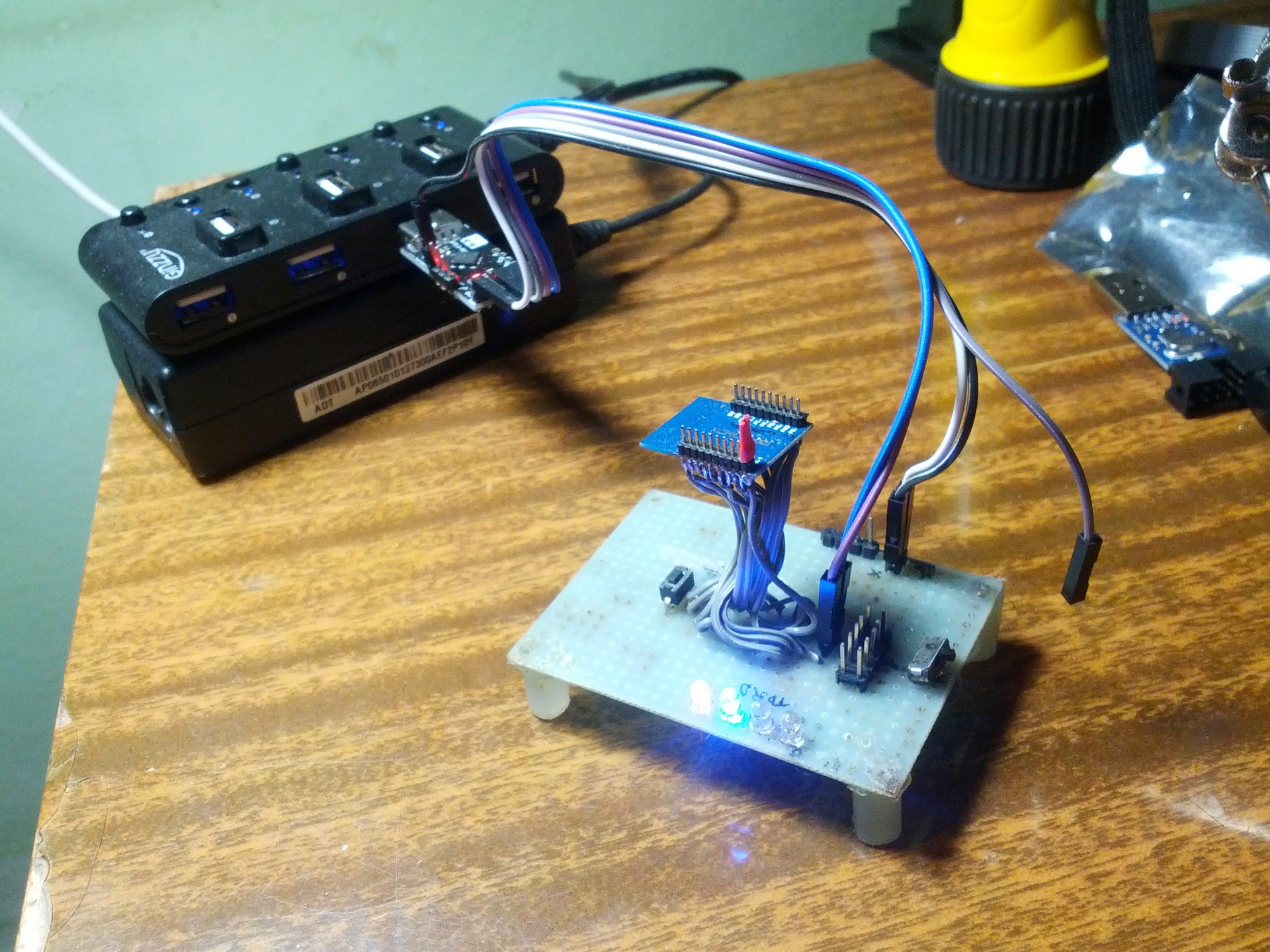
The server is the same nRF24LE1 module, connected via USB-UART converter to a PC, from which other devices on the network are controlled via a Java application. Photo below
The network filter is already working for the benefit of my home. The software is still raw and it makes no sense to show itand blush .
To those who are going to repeat this miracle, I can send a lightweight version of the firmware and server, as well as give a couple of tips:
Special thanks to Associate Professor Yuri Ivanovich Ivanov (Kaf. SAU, SFU) for help in the development of capacitor and other types of power supplies. Although they are not in this project, I will apply them in the following, and I will definitely tell you about this if the community approves this post.
I expect criticsand better praise and suggestions for improving the design.
Datasheet on nRF24LE1
Datasheet on BTA16
Datasheet on MOC3063
The control circuit of the power load with a more detailed description
Everything else is under the cut. Caution! A lot of pictures.
Foreword
First, I must say that in the city in which I now live, there is a very big problem with electronic components (resistors of 5p. Each, but we have never heard of microcontrollers here). I have to order everything or ask my comrades to transfer me from more advanced places in this plan. I hope this information will explain possible questions about the use of certain components. This is not my first device and, thanks to the use of ready-made modules, the need to draw schemes has disappeared. I present only the scheme of the triac key.
')
Components
I ordered wonderful modules with unsoldered nRF24LE1 from our beloved friends from heaven. About this microcontroller has already been written a lot on Habré ( here , and here , and here again), and it really helped at the start.
My modules, unlike most of those considered in Habré, are smaller in size and have PLS with a small step (by the way, the community can tell you how these pins are correctly named and where to get the mating part).
An ordinary, already tested by accountants and cleaners, a
Similarly, the simistors BTA16 (600v, 16A) and the opto-simistors MOC3063 were ordered from the Middle Kingdom. Partly was loose, partially bought.
So, fight!
Development process
To begin with, I disassembled the power filter to understand if I had enough space.
Places
Next for the firmware nRF24LE1 decided to use the microUSB connector. There are enough contacts, but you need to pull up the PROG input to the power supply in order to switch the micron to the programming mode. I decided to do a simple jumper (which I had to make myself from heat shrinkage and wire).
Separate, great, thanks to the post from MaksMS , as well as to him personally. The article and the correspondence with him greatly helped to start programming the nrf24le1, as well as to get the radio part.
So, the module responds to requests from the programmer (using USB ASP), go to the management of the power unit. To control the triac decided to use the opto-triac MOC3063. This microcircuit completely separates the power part from the low-voltage one, but there is one nuance. The MOC3063 has a built-in 0-crossing (zero-cross) detector in the power supply network and sends an opening pulse to the triac itself, which in turn leads to the fact that we cannot dim the outlet, but I did not pursue this goal. The wiring diagram is below:
The scheme is simple, I think, no further explanation is necessary. The only retreat, instead of the limiting resistor, was a green LED that will signal when the opacistor is turned on.
According to the scheme assembled, small modules for 5 outlets (only 3 in the photo):
Further, one of the lines in the network filter was cut in the indicated places, and from the cut-out gaps made jumpers on the “non-bonded” ends, so that when the plug was turned on they would not be strongly bent.
Soldered the control outputs of the triac modules to the pins of the microcontroller module 0.2, 0.1, 0.0, 1.6, 1.5.
5 yellow LEDs soldered to pins 0.7, 1.0, 1.1, 1.2, 1.3. By pins 0.5, 0.6, I soldered green and red LEDs to indicate the operation of the module (command parsing, receiving or sending data).
All this stuff is packaged in a network filter housing.
The triac modules fit perfectly in the gaps between the boxes for the plugs (in the photo they are green and gray wiring), under the modules there are green LEDs (in pre-drilled holes) in the opposite side from them, yellow LEDs are installed.
From the left in the middle are the ends of the two LEDs of the micron state.
Well, in the lower left corner you can see the radio itself with a hanging connector for programming.
Further, the biggest problem of the whole event: food for the microcontroller. At first I wanted to make a capacitor power supply, but I did not find the necessary capacitors and a zener diode in the city, but there was no desire to order and wait. I decided to use the power supply from charging for some phone.
He suffered for a long time with a block that was on top (with a red stripe), but it turned out that his optocoupler had burned down, and the zener diode on the block was extremely hot. It was very dangerous to put such a thing, and I decided to use a block that is below (with a yellow stripe), although I had to leave one of the home devices without power.
It is clear that the capacitor version would be much smaller, but the charging has a galvanic isolation, which allows in the future to bring a connector for programming outside the case.
However, the unit fits perfectly into the filter housing, and the whole structure has the following appearance:
After assembly in working condition:
Functional
Unfortunately, I can not yet post the firmware, because it is very confused. It was written taking into account the work on the network with many devices, and there is a lot of superfluous in it. If the community is interested
The principle of operation is as follows: when receiving a packet from the server, the module determines what should be done with the selected outlet and turns it on or off. In the off state, against the outlet, the yellow LED is on, in the on state, the green one is on.
Then I made a very serious mistake, it was necessary to drill holes for LEDs perpendicular to the holes for the plug. Since 80% of all power supplies that I found at home, either two LEDs or one of them close.
Little about the server
The server is the same nRF24LE1 module, connected via USB-UART converter to a PC, from which other devices on the network are controlled via a Java application. Photo below
Conclusion
The network filter is already working for the benefit of my home. The software is still raw and it makes no sense to show it
To those who are going to repeat this miracle, I can send a lightweight version of the firmware and server, as well as give a couple of tips:
- The LEDs should be installed perpendicularly, and for those specially provided with plexiglass, I recommend making a luminous stroke. Will be cool!
- The radio module itself should be installed in the opposite direction from the voltage input. The interference is less, and more space.
- Use short microUSB
- It is necessary to add the function of maintaining the state of pins when power is off. I myself plan to do this in the new firmware version
Special thanks to Associate Professor Yuri Ivanovich Ivanov (Kaf. SAU, SFU) for help in the development of capacitor and other types of power supplies. Although they are not in this project, I will apply them in the following, and I will definitely tell you about this if the community approves this post.
I expect critics
Required documentation
Datasheet on nRF24LE1
Datasheet on BTA16
Datasheet on MOC3063
The control circuit of the power load with a more detailed description
Source: https://habr.com/ru/post/221247/
All Articles