LED heart on Atmega16 microcontroller, or AVR programming in Pascal
LED heart on Atmega16 microcontroller, or AVR programming in Pascal
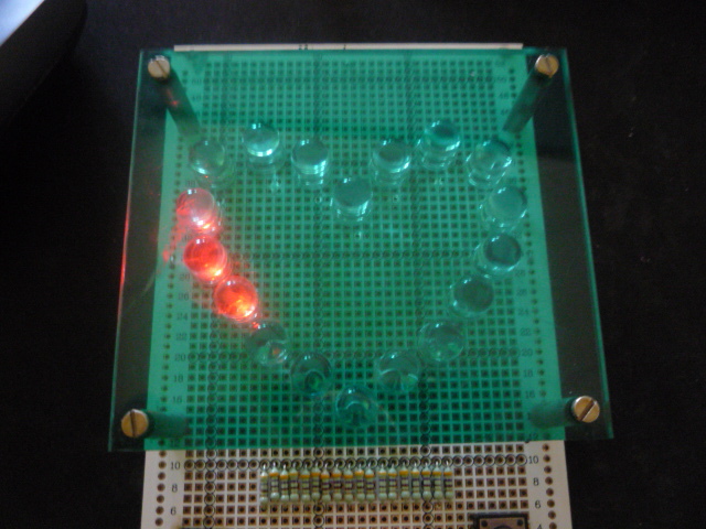
Once I decided to make a gift to my beloved girlfriend. For this, I armed myself with a soldering iron, a programmer and a computer. And, as an artist, made the LED heart. To make the heart special, I tried to implement all sorts of blinking LEDs.
')
Scheme
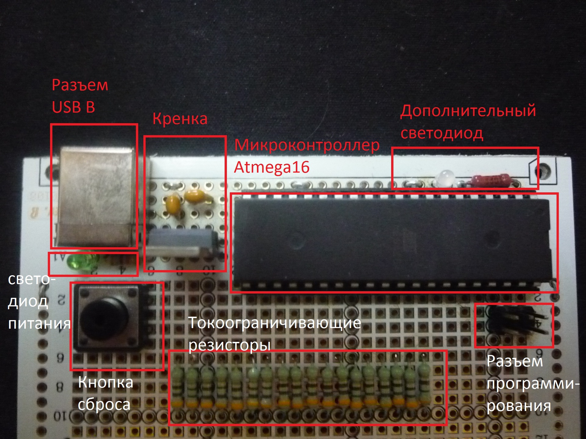
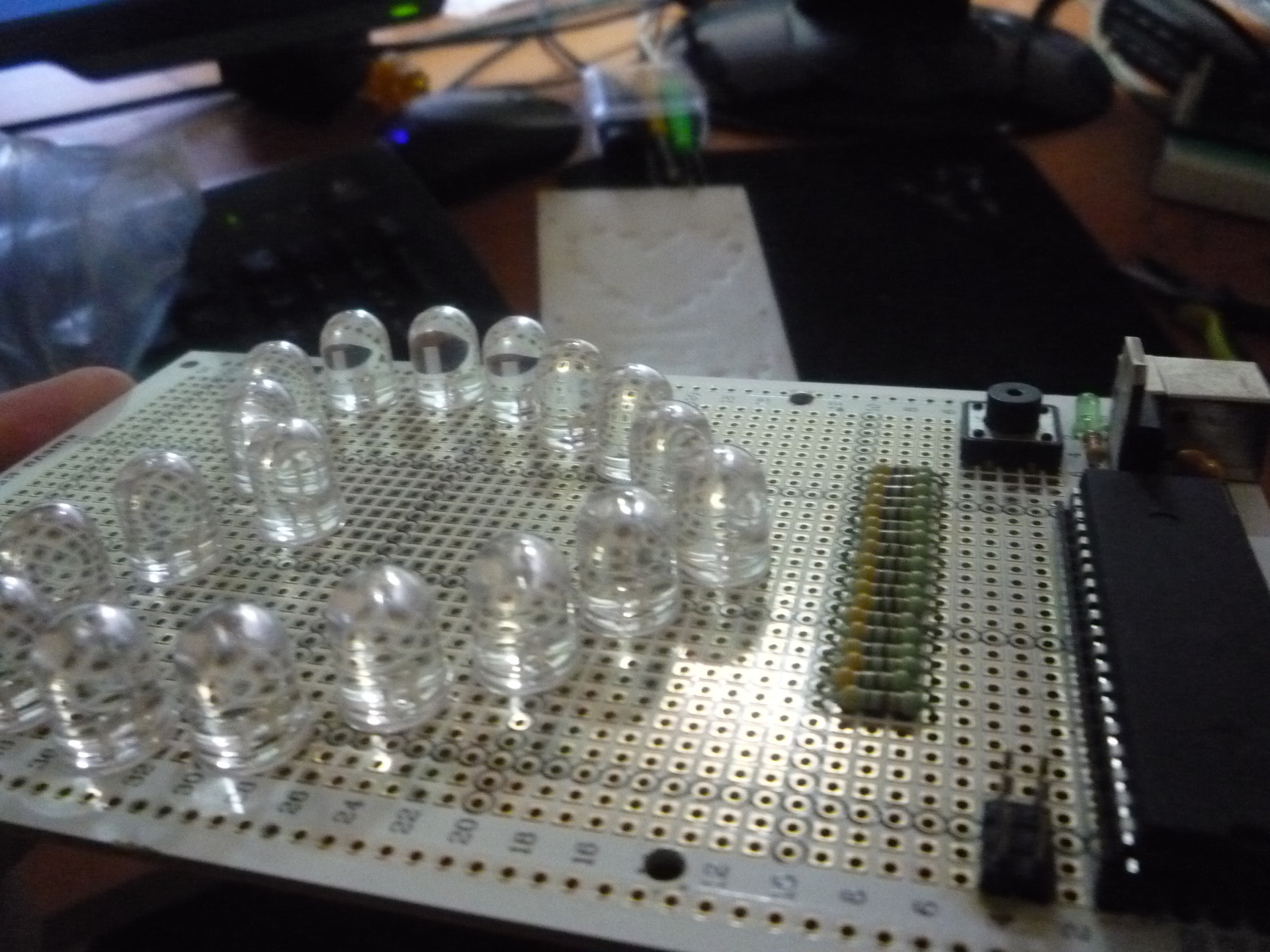
What is the scheme? There is nothing unusual here. The core of the heart, a kind of “pacemaker,” is the well-known AVR Atmega16 microcontroller, surrounded by the minimally necessary strapping. I didn’t clocking from quartz, the microcontroller runs on an internal RC-chain at a frequency of 1 MHz.
Each LED that forms the heart is connected to a separate “foot” of the microcontroller via a 500-ohm current-limiting resistor. Only eighteen LEDs connected to ports A (all pins), C (all pins), D (two pins). LEDs are controlled by a “one”.
Installation
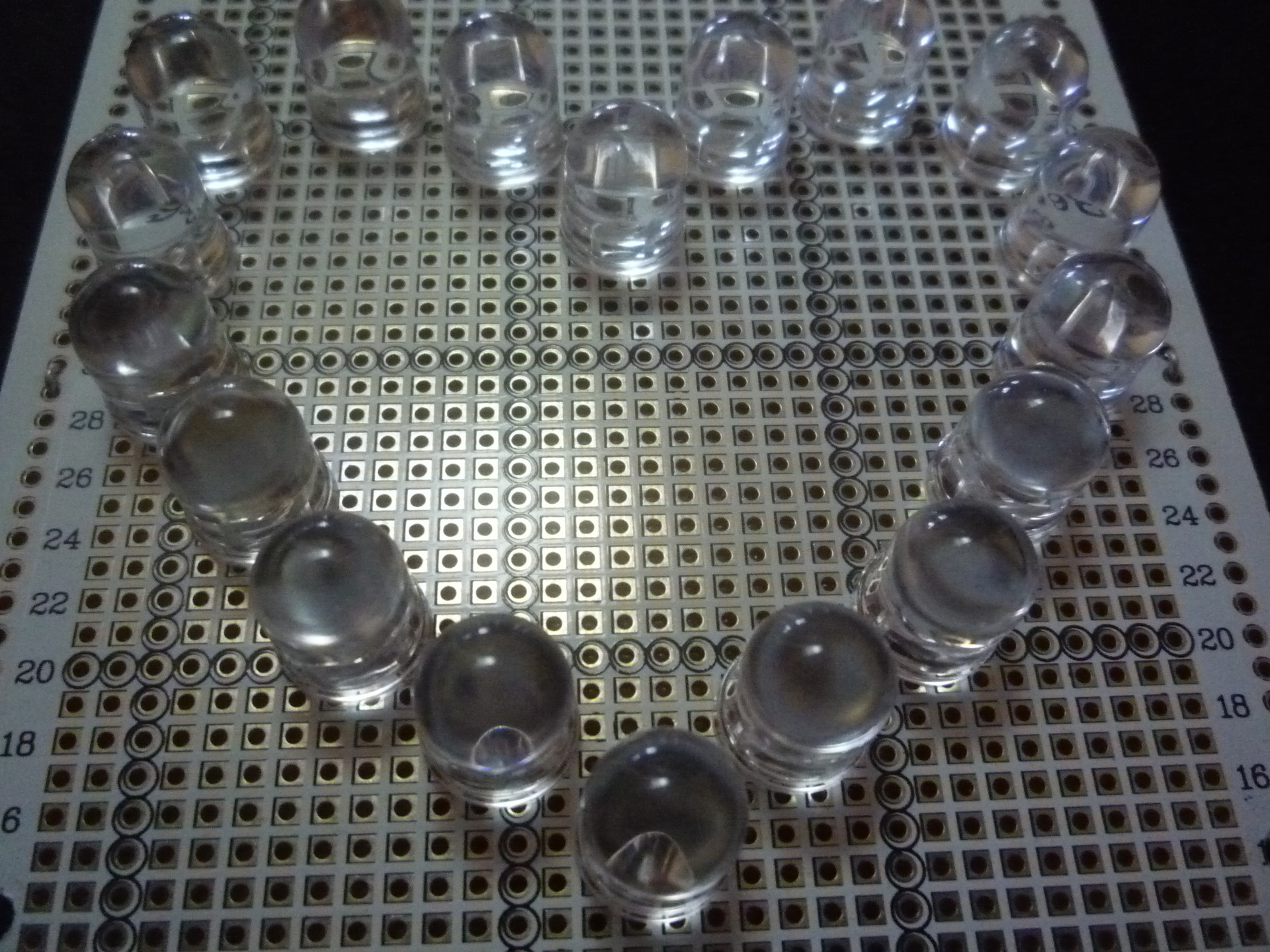
All elements were soldered with MGTF wire on a breadboard.
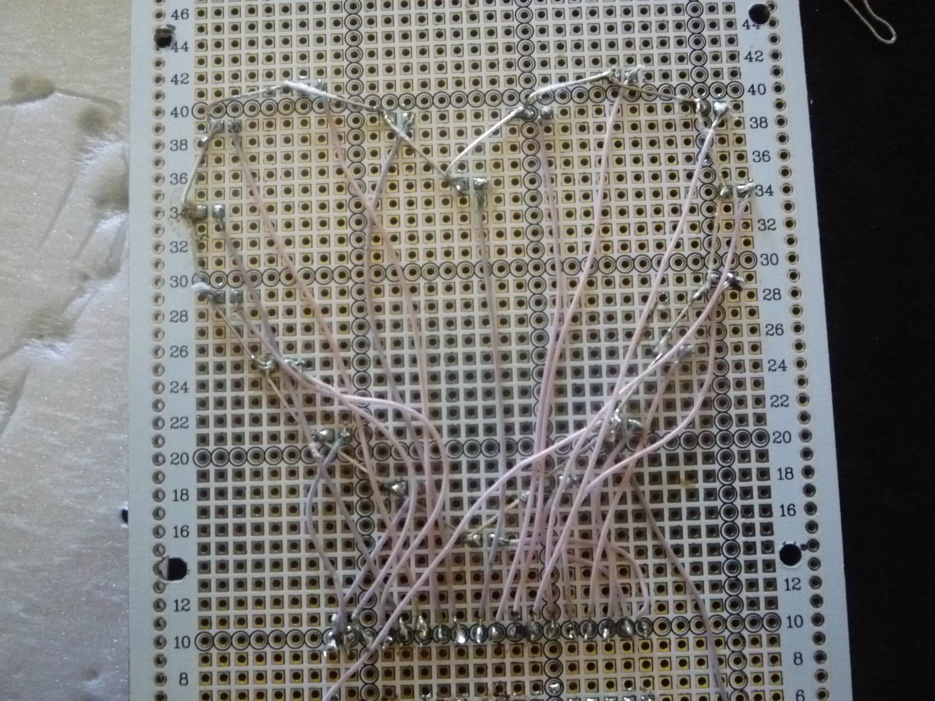
The development board at the back was "wired" with thin foam to protect the installation. Were also made "legs" of the racks, screwed.
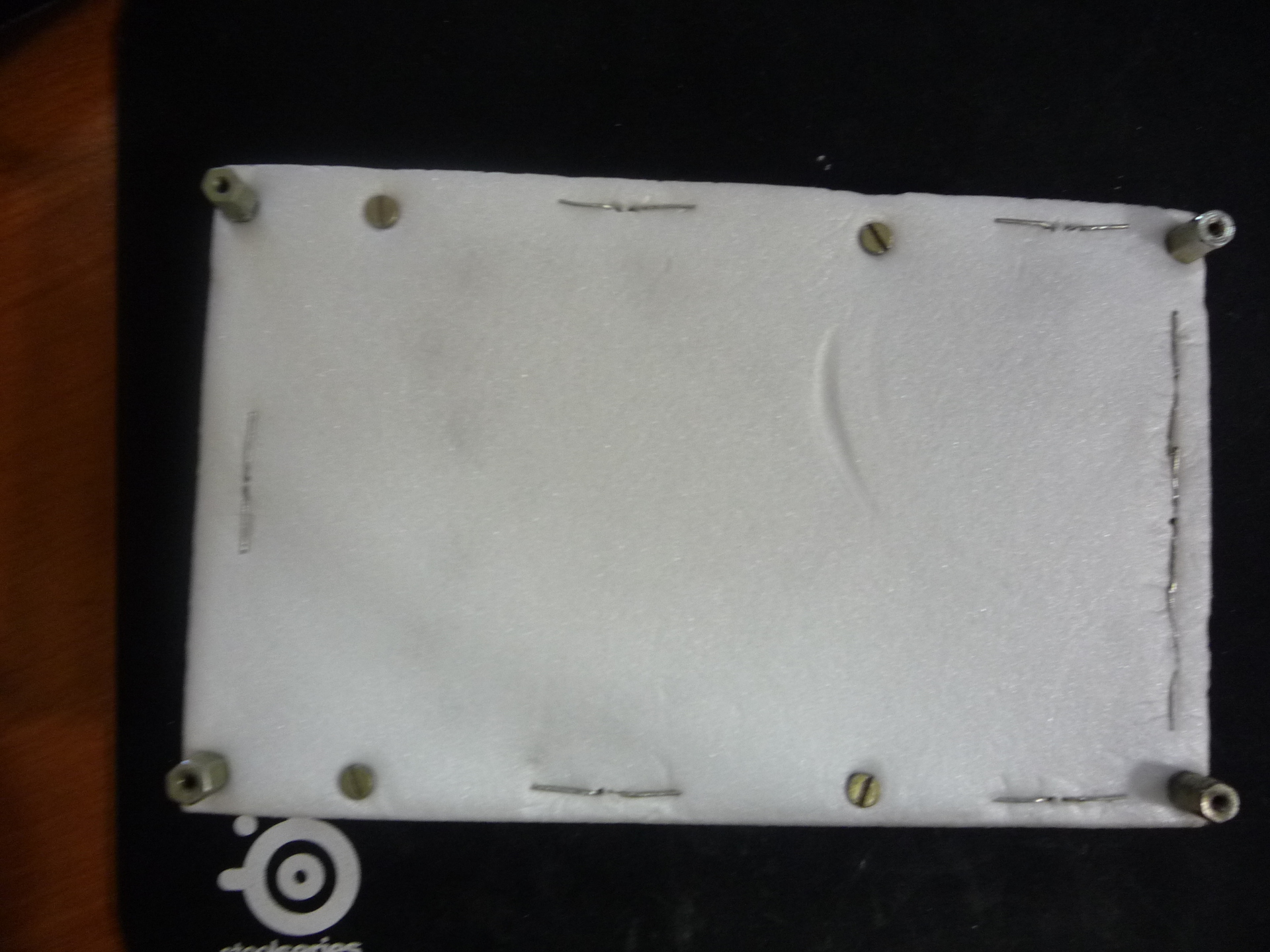
Because the LEDs turned out to be very bright, I had to make a muffling protective screen from green plexiglass and lift it to the racks. What pre-drilled holes.
Program
For programming the Atmega16 microcontroller I decided to use the E-LAB development environment. Why E-LAB? Probably the answer is that at that time the Arduino platform was not yet born. And for the implementation of such a project, a relatively simple and convenient tool was required. E-LAB is such a kind of “grandfather” of the Arduino IDE. E-LAB provides the creation of programs for AVR microcontrollers in the high-level programming language Pascal, which everyone knows. Although Pascal is a high-level language, knowledge of the architecture of AVR microcontrollers and the general principles of their operation is essential for the successful use of this language. E-LAB is a storehouse of libraries for working with peripheral modules built in the microcontroller (timers, PWM, I2C, UART, etc.), and with various external peripheral devices (keyboard, LCD sign, Ethernet, etc.) .d.)
The main logic of the program is to sequentially switch the display modes of the LEDs in the interrupt program timer. When I wrote this program, I did not use version control systems, so the latest version of the program was not preserved. But I found an intermediate version of the program, in which the main modes of operation, in particular the program 18-channel PWM, are present.
Pascal text
program Love_Machine;
{$ NOSHADOW}
{$ WG} {global Warnings off}
// ATmega16 controller
// 3.3 V supply voltage
Device = mega16, VCC = 3.3;
{$ BOOTRST $ 01C00} {Reset Jump to $ 01C00}
Import SysTick, TickTimer;
From System Import LongWord;
Define
// 1 MHz Operating Frequency (Internal RC Chain)
ProcClock = 1,000,000; {Hertz}
SysTick = 10; {msec}
StackSize = $ 0032, iData;
FrameSize = $ 0032, iData;
TickTimer = Timer1;
// Delay switching system
// in milliseconds
Define_USR SysLED_Delay = 500;
Implementation
{$ IDATA}
{------------------------------------------------- -------------}
{Type Declarations}
type
{------------------------------------------------- -------------}
{Const Declarations}
const
TimeCount: Byte = 70;
MOutBits_L1: array [0..7] of Byte = (
$ 00,
$ 00,
$ 00,
$ 00,
$ 00,
$ 00,
$ 00,
$ ff
);
MOutBits_L2: array [0..7] of Byte = (
$ 00,
$ 00,
$ 00,
$ 00,
$ 00,
$ 00,
$ ff,
$ ff
);
MOutBits_L3: array [0..7] of Byte = (
$ 00,
$ 00,
$ 00,
$ 00,
$ 00,
$ ff,
$ ff,
$ ff
);
MOutBits_L4: array [0..7] of Byte = (
$ 00,
$ 00,
$ 00,
$ 00,
$ ff,
$ ff,
$ ff,
$ ff
);
MOutBits_L5: array [0..7] of Byte = (
$ 00,
$ 00,
$ 00,
$ ff,
$ ff,
$ ff,
$ ff,
$ ff
);
MOutBits_L6: array [0..7] of Byte = (
$ 00,
$ 00,
$ ff,
$ ff,
$ ff,
$ ff,
$ ff,
$ ff
);
MOutBits_L7: array [0..7] of Byte = (
$ 00,
$ ff,
$ ff,
$ ff,
$ ff,
$ ff,
$ ff,
$ ff
);
{*
MOutBits: array [0..24] of LongWord = (
% 010000000000000101,
% 010000000000000101,
% 010000000000000101,
% 010000000000000101,
% 010000000000000101,
% 0100000000000001,
% 0100000000000001,
% 0100000000000001,
% 0100000000000001,
% 0100000000000001,
% 0100000000000001,
% 0100000000000001,
% 0100000000000001,
% 0100000000000001,
% 0100000000000001,
% 000000000000000101,
% 000000000000000101,
% 000000000000000101,
% 000000000000000101,
% 000000000000000101,
% 000000000000000001
% 000000000000000001
% 000000000000000001
% 000000000000000001
% 000000000000000001
);
*}
{------------------------------------------------- -------------}
{Var Declarations}
{$ IDATA}
var
OutBitsIndex: Byte;
St_Level: Byte;
St_Timer: Byte;
PortDataA: Byte;
PortDataC: Byte;
PortDataD: Byte;
ShiftCounter: Byte;
TimerTickCounter: LongWord;
{------------------------------------------------- -------------}
{functions}
// Initialization function
// I / O ports
procedure InitPorts;
begin
// The first segment of the heart (8 LEDs)
// Port to output
DDRA: =% 11111111;
// Write the zeros
PortA: =% 00000000;
// The second segment of the heart
// Port to output
DDRC: =% 11111111;
// Write the zeros
PortC: =% 00000000;
// The third segment of the heart ()
// Two output port to output
DDRD: =% 00000011;
// Write the zeros
PortD: =% 00000000;
// system two-color LED (2 legs)
// Port to output
DDRB: =% 00000011;
end initPorts;
// Indication in red
procedure SysLED_Red;
begin
// Pull the 1st pin to the unit
// port B
incl (PortB, 1);
// Pull the 0th output to zero
// port B
excl (PortB, 0);
end SysLED_Red;
// Display Green
procedure SysLED_Green;
begin
// Pull the 0th output to the unit
// port B
incl (portb, 0);
// Pull the 1st pin to zero
// port B
excl (PortB, 1);
end SysLED_Green;
// Toggle display
// green-red
procedure SysLED_SwColor;
begin
// Light Red
SysLED_Red;
//Delay
mDelay (Word (SysLED_Delay));
// Light Green
SysLED_Green;
//Delay
mDelay (Word (SysLED_Delay));
end SysLED_SwColor;
// Program timer interrupt handler
procedure onTickTimer; // (SaveAllRegs);
begin
// SysLED_SwColor;
case St_Timer of
0:
toggle (PortA, 0);
toggle (PortA, 1);
toggle (PortA, 2);
toggle (PortA, 3);
toggle (PortA, 4);
toggle (PortA, 5);
toggle (PortA, 6);
toggle (PortA, 7);
toggle (PortC, 0);
toggle (PortC, 1);
toggle (PortC, 2);
toggle (PortC, 3);
toggle (PortC, 4);
toggle (PortC, 5);
toggle (PortC, 6);
toggle (PortC, 7);
toggle (PortD, 0);
toggle (PortD, 1);
|
one:
PortDataA: = PortDataA ror 1;
PortA: = PortDataA;
PortDataC: = PortDataC ror 1;
PortC: = PortDataC;
PortDataD: = PortDataD ror 1;
PortD: = PortDataD;
|
2:
// PortDataC: = PortDataC ror 1;
// PortC: = PortDataC;
// PortDataD: = PortDataD ror 1;
// PortD: = PortDataD;
if (ShiftCounter = 0) or (ShiftCounter = 18)
then
PortD: = $ 00;
ShiftCounter: = 0;
PortDataA: = $ 01;
PortA: = PortDataA;
inc (ShiftCounter);
elsif (ShiftCounter <8) and (ShiftCounter> 0)
then
PortDataA: = PortDataA rol 1;
PortA: = PortDataA;
inc (ShiftCounter);
elsif (ShiftCounter = 8)
then
PortA: = $ 00;
PortDataC: = $ 01;
PortC: = PortDataC;
inc (ShiftCounter);
elsif (ShiftCounter> 8) and (ShiftCounter <16)
then
PortDataC: = PortDataC rol 1;
PortC: = PortDataC;
inc (ShiftCounter);
elsif (ShiftCounter = 16)
then
PortC: = $ 00;
PortDataD: = $ 01;
PortD: = PortDataD;
inc (ShiftCounter);
elsif (ShiftCounter> 16) and (ShiftCounter <18)
then
PortDataD: = PortDataD rol 1;
PortD: = PortDataD;
inc (ShiftCounter);
endif;
|
3:
inc (TimerTickCounter);
if ((TimerTickCounter mod TimeCount) = 0)
then
inc (St_Level);
if (St_Level> = 16)
then
St_Level: = 1;
endif;
endif;
case St_Level of
0:
PortA: = $ 00;
PortC: = $ 00;
PortD: = $ 00;
|
one:
PortA: = MOutBits_L1 [OutBitsIndex];
PortC: = MOutBits_L1 [OutBitsIndex];
PortD: = MOutBits_L1 [OutBitsIndex];
|
2:
PortA: = MOutBits_L2 [OutBitsIndex];
PortC: = MOutBits_L2 [OutBitsIndex];
PortD: = MOutBits_L2 [OutBitsIndex];
|
3:
PortA: = MOutBits_L3 [OutBitsIndex];
PortC: = MOutBits_L3 [OutBitsIndex];
PortD: = MOutBits_L3 [OutBitsIndex];
|
four:
PortA: = MOutBits_L4 [OutBitsIndex];
PortC: = MOutBits_L4 [OutBitsIndex];
PortD: = MOutBits_L4 [OutBitsIndex];
|
five:
PortA: = MOutBits_L5 [OutBitsIndex];
PortC: = MOutBits_L5 [OutBitsIndex];
PortD: = MOutBits_L5 [OutBitsIndex];
|
6:
PortA: = MOutBits_L6 [OutBitsIndex];
PortC: = MOutBits_L6 [OutBitsIndex];
PortD: = MOutBits_L6 [OutBitsIndex];
|
7:
PortA: = MOutBits_L7 [OutBitsIndex];
PortC: = MOutBits_L7 [OutBitsIndex];
PortD: = MOutBits_L7 [OutBitsIndex];
|
eight:
PortA: = $ FF;
PortC: = $ FF;
PortD: = $ FF;
|
9:
PortA: = MOutBits_L7 [OutBitsIndex];
PortC: = MOutBits_L7 [OutBitsIndex];
PortD: = MOutBits_L7 [OutBitsIndex];
|
ten:
PortA: = MOutBits_L6 [OutBitsIndex];
PortC: = MOutBits_L6 [OutBitsIndex];
PortD: = MOutBits_L6 [OutBitsIndex];
|
eleven:
PortA: = MOutBits_L5 [OutBitsIndex];
PortC: = MOutBits_L5 [OutBitsIndex];
PortD: = MOutBits_L5 [OutBitsIndex];
|
12:
PortA: = MOutBits_L4 [OutBitsIndex];
PortC: = MOutBits_L4 [OutBitsIndex];
PortD: = MOutBits_L4 [OutBitsIndex];
|
13:
PortA: = MOutBits_L3 [OutBitsIndex];
PortC: = MOutBits_L3 [OutBitsIndex];
PortD: = MOutBits_L3 [OutBitsIndex];
|
14:
PortA: = MOutBits_L2 [OutBitsIndex];
PortC: = MOutBits_L2 [OutBitsIndex];
PortD: = MOutBits_L2 [OutBitsIndex];
|
15:
PortA: = MOutBits_L1 [OutBitsIndex];
PortC: = MOutBits_L1 [OutBitsIndex];
PortD: = MOutBits_L1 [OutBitsIndex];
|
endcase;
inc (OutBitsIndex);
if OutBitsIndex> = 8
then
OutBitsIndex: = 0;
endif;
|
endcase;
end;
{------------------------------------------------- -------------}
{Main Program}
{$ IDATA}
// Code executed immediately after Reset'a
begin
// Initialize I / O Ports
InitPorts;
// Set the program timer
// Period = 1 ms
// Frequency = 1 kHz
TickTimerTime (1000);
// Start the timer
TickTimerStart;
// Stop The Timer
TickTimerStop;
// Enable interrupts
EnableInts;
{
// Sequential inclusion
// LEDs with a second interval
incl (PortA, 0);
mDelay (1000);
incl (PortA, 1);
mDelay (1000);
incl (PortA, 2);
mDelay (1000);
incl (PortA, 3);
mDelay (1000);
incl (PortA, 4);
mDelay (1000);
incl (PortA, 5);
mDelay (1000);
incl (PortA, 6);
mDelay (1000);
incl (PortA, 7);
mDelay (1000);
incl (portc, 0);
mDelay (1000);
incl (portc, 1);
mDelay (1000);
incl (portc, 2);
mDelay (1000);
incl (portc, 3);
mDelay (1000);
incl (portc, 4);
mDelay (1000);
incl (portc, 5);
mDelay (1000);
incl (portc, 6);
mDelay (1000);
incl (portc, 7);
mDelay (1000);
incl (PortD, 0);
mDelay (1000);
incl (PortD, 1);
mDelay (1000);
// Go to the first timer mode (Toggle)
St_Timer: = 0;
// 200 ms period
TickTimerTime (200000);
// Start the timer
TickTimerStart;
// Delay 2 seconds
mDelay (2000);
// 150 ms period
TickTimerTime (150000);
// Start the timer
TickTimerStart;
mDelay (2000);
// Stop The Timer
TickTimerStop;
// Period 100 ms
TickTimerTime (100000);
// Start the timer
TickTimerStart;
// Delay 2 seconds
mDelay (2000);
// Stop The Timer
TickTimerStop;
// Period 50 ms
TickTimerTime (50,000);
// Start the timer
TickTimerStart;
// Delay 2 seconds
mDelay (2000);
// Stop The Timer
TickTimerStop;
// Period 25 ms
TickTimerTime (25000);
// Start the timer
TickTimerStart;
// Delay 2 seconds
mDelay (2000);
}
// Stop The Timer
TickTimerStop;
PortDataA: = $ AA;
PortDataC: = $ AA;
PortDataD: = $ AA;
// Transition to the second mode (Shift Inv)
St_Timer: = 1;
// 200 ms period
TickTimerTime (200000);
// Start the timer
TickTimerStart;
// Delay 5 seconds
mDelay (2000);
// Stop The Timer
TickTimerStop;
PortA: = $ 00;
PortC: = $ 00;
PortD: = $ 00;
PortDataA: = $ 00;
PortDataC: = $ 00;
PortDataD: = $ 00;
ShiftCounter: = 0;
// Go to the second mode (Shift One)
St_Timer: = 2;
// 200 ms period
TickTimerTime (200000);
// Start the timer
TickTimerStart;
// Delay 5 seconds
mDelay (5000);
// Stop The Timer
TickTimerStop;
// Transition to the third timer mode (PWM)
St_Timer: = 3;
// Frequency = 1 kHz
TickTimerTime (1000);
// Start the timer
TickTimerStart;
// Main loop
loop
// inc (St_Level);
// if (St_Level> = 9)
// then
// St_Level: = 0;
// endif;
// mDelay (200);
// SysLED_SwColor;
// incl (PortC, 1);
// mDelay (1);
endloop;
end Love_Machine.
A serious disadvantage of E-LAB, was and is that for programming from the environment a special branded programmer is needed. Not having one, I stitched a hex-file into the microcontroller with the “people's” AVR910 programmer of my own production.
Conclusion
I think that now, a similar gift on the Arduino platform can be made by everyone, and thus please their loved ones. There would be a desire.
Source: https://habr.com/ru/post/220981/
All Articles