Reverse Engineering for the smallest: breaking keygen
This post will be really interesting to those who are just beginning to be interested in this topic. For people with experience, he may only cause yawns. Except maybe an epilogue ...
Reverse engineering in the less legal part, where it does not deal with debugging and optimizing its own product, also concerns the following task: “find out how it works for them”. In other words, the restoration of the original algorithm of the program, having on hand its executable file.
In order to hold on to the basics and avoid some of the problems - “hack” is not something, but ... keygen. In 90% it will not be packaged, encrypted or otherwise protected - including the norms of international law ...
So, we need a keygen and disassembler. As for the second, let's assume that it will be Ida Pro. An experimental nameless keygen found on the web:
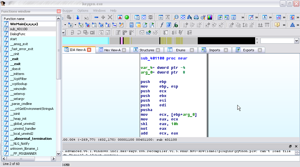
Opening the keygen file in Ida, we see a list of functions.

After analyzing this list, we see several standard functions (WinMain, start, DialogFunc) and a bunch of auxiliary-system functions. These are all standard features that make up the framework.
User functions that represent the implementation of the program's tasks, and not its wrapper from API-system and system calls, the disassembler does not recognize and simply calls sub_number. Considering that there is only one such function here - it should attract our attention as, most likely, containing the algorithm we are interested in or part of it.
')
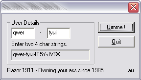
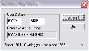
Let's run keygen. He asks for two 4-digit lines. Suppose eight characters are sent to the key calculation function at once. Analyzing the function code sub_401100. The answer to the hypothesis is contained in the first two lines:
The second line unambiguously hints at receiving the function argument at offset 8. However, the size of the argument is a double word equal to 4 bytes, not 8. This means that the function processes one line of four characters most likely in one pass, but it is called twice.
The question that can probably arise is: why is an offset of 8 bytes reserved for receiving the function argument, but pointing to 4, because there is only one argument? As we remember, the stack grows down; adding values to the stack reduces the stack pointer by the corresponding number of bytes. Therefore, after adding the function argument to the stack and before it starts working, something else is added to the stack. This is obviously the return address that is added to the stack after calling the system call function.
We will find places in the program where there are calls to the sub401100 function. There are actually two of them: at the address DialogFunc + 97 and DialogFunc + 113. Instructions of interest to us begin here:
First, the two functions SendDlgItemMessageA are called in a row. This function takes an element handle and sends it a system Msg message. In our case, the Msg in both cases is 0Dh, which is the hexadecimal equivalent of the WM_GETTEXT constant. Here, the values of two text fields in which the user entered “two 4-character strings” are extracted. The letter A in the name of the function indicates that the ASCII format is used - one byte per character.
The first line is written by the offset lParam, the second, which is obvious - by the offset var_1C.
So, after performing the SendDlgItemMessageA functions, the current state of the registers is saved on the stack using the pusha command, then one byte of one of the lines is written to the ecx, edx and eax registers. As a result, each of the registers takes the form: 000000 ##. Then:
Then this value is stored in the “variable” - in the memory area at the offset arg_4. The state of the registers (their previous values), previously stored on the stack, is pulled out of the stack and distributed to the registers. Then the value of arg_4 is written back to the register eah and this value is pushed out of the register to the stack. After that the function call sub_401100 follows.
What is the meaning of these operations? It is very easy to figure out, even in practice, without theory. Put a breakpoint in the debugger, for example, on the push eax instruction (just before the subfunction call) and run the program for execution. Keigen will start, ask to enter lines. Enter qwer and tyui and stop at breakpoint, look at the value of eax: 72657771. Decode to text: rewq. That is, the physical meaning of these operations is string inversion.
We now know that in sub_401100 one of the source strings is transmitted, inverted backwards, in the size of a double word, which completely fits in any of the standard registers. Perhaps you can take a look at the sub_401100 instructions.
At the very beginning there is nothing interesting here - the state of the registers is carefully stored in the stack. But the first team that interests us is the one following the PUSHA instruction. It writes the function argument to the EXC, stored at the offset arg_0. Then this value is transferred to eax. And cut in half: as we remember, in our example, 72657771 is transmitted in sub_401100; a logical left shift of 10h (16 decimal) turns the register value into 77710000.
After this, the register value is inverted by the NOT instruction. This means that in the binary representation of the register, all zeros are turned into ones, and ones - into zeros. Register after the execution of this instruction contains 888FFFF.
The ADD instruction adds (adds, plus, etc.) the resulting value to the initial value of the argument, which is still contained in the eX register (now it is clear why it was written first in eX, and then in eax?). The result is saved in the Ex. Check how it will look like after this operation: FAF47770.
This result is copied from ec to eax, after which the SHR instruction is applied to the content eax. This operation is the opposite of SHL - if the latter shifts digits to the left, then the first shifts them to the right. Just as a logical left shift operation is equivalent to multiplying by powers of two, a logical right shift operation is equivalent to the same division. Let's see what value will be the result of this operation: 7D7A3BB.
Now let's commit another violence against the contents of eax and ecx: the XOR instruction is modulo 2 addition or “exclusive OR”. The essence of this operation, roughly speaking, is that its result is equal to one (true) only if its operands are significant. For example, in the case of 0 xor 1, the result is true, or one. In the case of 0 xor 0 or 1 xor 1, the result will be false, or zero. In our case, as a result of executing this instruction, with regard to the registers eax (7D7A3BB) and exx (FAF47770), the value FD23D4CB is written to the register eax.
The following command LEA ecx, [eax + eax * 8] elegantly and naturally multiplies e by 9 and records the result in ec. Then this value is copied to edx and shifted to the right by 13 digits: we get 73213 in edx and E6427B23 in Ex. Then again xorim ecx and edx, writing in ecx E6454930. Copy it in eax, move it to the left by 9 bits: 8926000, then we invert it, getting 756D9FFF. We add this value to the ech register - we have 5BB2E92F. We copy it in eax, we shift to the right by as much as 17 digits - 2DD9 - and xorym with ecx. We end up with 5BB2C4F6. Then ... then ... what about us? What all?..
So, we save this value to the memory area at var_4 offset, load the register status from the stack, again take the total value from memory and finally retrieve the remaining register states saved at the beginning from the stack. Exit the function. Hooray! .. However, it is still too early to rejoice, so far we have a maximum of four semi-printed characters at the output of the first function call, and yet we still have a whole raw line, and we need to bring this one to the divine form.
Let's move to a higher level of analysis - from the disassembler to the decompiler. Imagine the entire function DialogFunc, which contains calls to sub_401100, in the form of C-like pseudocode. As a matter of fact, this disassembler calls it “pseudocode”, in practice it is practically C code, only ugly. We look:
It is already easier to read than an assembler listing. However, not in all cases you can rely on the decompiler: you need to be ready for hours to monitor the thread of assembler logic, the state of registers and stack in the debugger ... and then give written explanations to the FSB or the FBI. In the evening I have a particularly funny joke.
As I said, it is easier to read, but still far from perfect. Let's analyze the code and give the variables more readable names. We give clear and logical names to the key variables, and simpler and temporary ones.
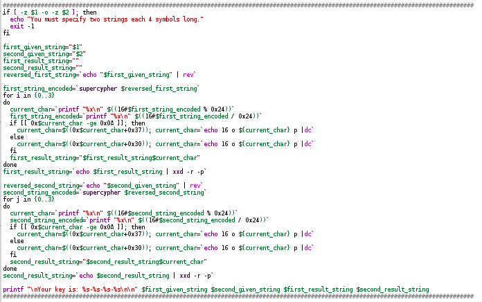
Level complete . The next (and final) goal is to write your keygen using this algorithm. I will, out of habit, write in the Linux shell script bash script language. test $ {# reg1} -gt && reg1 = `echo" $ {reg1: -8} "` is cutting the string that contains the emulated register value, up to 8 low characters. When performing operations, extra high-order bits were added there. All the rest is painstaking emulation of assembly listing. I pointed at the top of the “Abnormal programming” hub, right? ..
bash-implementation of the notorious sub_401100:

The main function of keygen:
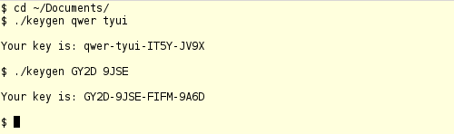
Testing and comparison:
Now we could generate keys to some gaming software directly from the Linux console, but this is impossible for several reasons: firstly, I don’t know what software this target is intended for - I downloaded it at random on the Internet; secondly, the use of fake keys and unlicensed proprietary software is prohibited by international law. ;)

Reverse engineering in the less legal part, where it does not deal with debugging and optimizing its own product, also concerns the following task: “find out how it works for them”. In other words, the restoration of the original algorithm of the program, having on hand its executable file.
In order to hold on to the basics and avoid some of the problems - “hack” is not something, but ... keygen. In 90% it will not be packaged, encrypted or otherwise protected - including the norms of international law ...
In the beginning was the word. Double
So, we need a keygen and disassembler. As for the second, let's assume that it will be Ida Pro. An experimental nameless keygen found on the web:
Opening the keygen file in Ida, we see a list of functions.
After analyzing this list, we see several standard functions (WinMain, start, DialogFunc) and a bunch of auxiliary-system functions. These are all standard features that make up the framework.
User functions that represent the implementation of the program's tasks, and not its wrapper from API-system and system calls, the disassembler does not recognize and simply calls sub_number. Considering that there is only one such function here - it should attract our attention as, most likely, containing the algorithm we are interested in or part of it.
')
Let's run keygen. He asks for two 4-digit lines. Suppose eight characters are sent to the key calculation function at once. Analyzing the function code sub_401100. The answer to the hypothesis is contained in the first two lines:
var_4 = dword ptr -4
arg_0 = dword ptr 8
The second line unambiguously hints at receiving the function argument at offset 8. However, the size of the argument is a double word equal to 4 bytes, not 8. This means that the function processes one line of four characters most likely in one pass, but it is called twice.
The question that can probably arise is: why is an offset of 8 bytes reserved for receiving the function argument, but pointing to 4, because there is only one argument? As we remember, the stack grows down; adding values to the stack reduces the stack pointer by the corresponding number of bytes. Therefore, after adding the function argument to the stack and before it starts working, something else is added to the stack. This is obviously the return address that is added to the stack after calling the system call function.
We will find places in the program where there are calls to the sub401100 function. There are actually two of them: at the address DialogFunc + 97 and DialogFunc + 113. Instructions of interest to us begin here:
Relatively long piece of code
loc_401196: mov esi, [ebp+hDlg] mov edi, ds:SendDlgItemMessageA lea ecx, [ebp+lParam] push ecx ; lParam push 0Ah ; wParam push 0Dh ; Msg push 3E8h ; nIDDlgItem push esi ; hDlg call edi ; SendDlgItemMessageA lea edx, [ebp+var_1C] push edx ; lParam push 0Ah ; wParam push 0Dh ; Msg push 3E9h ; nIDDlgItem push esi ; hDlg call edi ; SendDlgItemMessageA pusha movsx ecx, byte ptr [ebp+lParam+2] movsx edx, byte ptr [ebp+lParam+1] movsx eax, byte ptr [ebp+lParam+3] shl eax, 8 or eax, ecx movsx ecx, byte ptr [ebp+lParam] shl eax, 8 or eax, edx shl eax, 8 or eax, ecx mov [ebp+arg_4], eax popa mov eax, [ebp+arg_4] push eax call sub_401100 First, the two functions SendDlgItemMessageA are called in a row. This function takes an element handle and sends it a system Msg message. In our case, the Msg in both cases is 0Dh, which is the hexadecimal equivalent of the WM_GETTEXT constant. Here, the values of two text fields in which the user entered “two 4-character strings” are extracted. The letter A in the name of the function indicates that the ASCII format is used - one byte per character.
The first line is written by the offset lParam, the second, which is obvious - by the offset var_1C.
So, after performing the SendDlgItemMessageA functions, the current state of the registers is saved on the stack using the pusha command, then one byte of one of the lines is written to the ecx, edx and eax registers. As a result, each of the registers takes the form: 000000 ##. Then:
- The SHL command shifts the bit content of the eax register by 1 byte, or in other words, multiplies the arithmetic content by 100 in the hexadecimal system or by 256 in the decimal. As a result, eax takes the form 0000 ## 00 (for example, 00001200).
- An OR operation is performed between the received eax value and the ecx register in the form 000000 ## (let it be 00000034). As a result, the eax will look like: 00001234.
- The last, fourth byte of the string is written to the “freed” exx.
- The content each is shifted by byte again, freeing up space in the lower byte for the next OR command. Now it looks like this: 00123400.
- The OR instruction is executed, this time between eax and edx, which contains, say, 00000056. Now, eax is 00123456.
- Two steps SHL eax, 8 and OR are repeated, with the result that the new content ecx (00000078) is added to the “end” eax. As a result, eah stores the value 12345678.
Then this value is stored in the “variable” - in the memory area at the offset arg_4. The state of the registers (their previous values), previously stored on the stack, is pulled out of the stack and distributed to the registers. Then the value of arg_4 is written back to the register eah and this value is pushed out of the register to the stack. After that the function call sub_401100 follows.
What is the meaning of these operations? It is very easy to figure out, even in practice, without theory. Put a breakpoint in the debugger, for example, on the push eax instruction (just before the subfunction call) and run the program for execution. Keigen will start, ask to enter lines. Enter qwer and tyui and stop at breakpoint, look at the value of eax: 72657771. Decode to text: rewq. That is, the physical meaning of these operations is string inversion.
We now know that in sub_401100 one of the source strings is transmitted, inverted backwards, in the size of a double word, which completely fits in any of the standard registers. Perhaps you can take a look at the sub_401100 instructions.
Another relatively long piece of code
sub_401100 proc near var_4= dword ptr -4 arg_0= dword ptr 8 push ebp mov ebp, esp push ecx push ebx push esi push edi pusha mov ecx, [ebp+arg_0] mov eax, ecx shl eax, 10h not eax add ecx, eax mov eax, ecx shr eax, 5 xor eax, ecx lea ecx, [eax+eax*8] mov edx, ecx shr edx, 0Dh xor ecx, edx mov eax, ecx shl eax, 9 not eax add ecx, eax mov eax, ecx shr eax, 11h xor eax, ecx mov [ebp+var_4], eax popa mov eax, [ebp+var_4] pop edi pop esi pop ebx mov esp, ebp pop ebp retn sub_401100 endp At the very beginning there is nothing interesting here - the state of the registers is carefully stored in the stack. But the first team that interests us is the one following the PUSHA instruction. It writes the function argument to the EXC, stored at the offset arg_0. Then this value is transferred to eax. And cut in half: as we remember, in our example, 72657771 is transmitted in sub_401100; a logical left shift of 10h (16 decimal) turns the register value into 77710000.
After this, the register value is inverted by the NOT instruction. This means that in the binary representation of the register, all zeros are turned into ones, and ones - into zeros. Register after the execution of this instruction contains 888FFFF.
The ADD instruction adds (adds, plus, etc.) the resulting value to the initial value of the argument, which is still contained in the eX register (now it is clear why it was written first in eX, and then in eax?). The result is saved in the Ex. Check how it will look like after this operation: FAF47770.
This result is copied from ec to eax, after which the SHR instruction is applied to the content eax. This operation is the opposite of SHL - if the latter shifts digits to the left, then the first shifts them to the right. Just as a logical left shift operation is equivalent to multiplying by powers of two, a logical right shift operation is equivalent to the same division. Let's see what value will be the result of this operation: 7D7A3BB.
Now let's commit another violence against the contents of eax and ecx: the XOR instruction is modulo 2 addition or “exclusive OR”. The essence of this operation, roughly speaking, is that its result is equal to one (true) only if its operands are significant. For example, in the case of 0 xor 1, the result is true, or one. In the case of 0 xor 0 or 1 xor 1, the result will be false, or zero. In our case, as a result of executing this instruction, with regard to the registers eax (7D7A3BB) and exx (FAF47770), the value FD23D4CB is written to the register eax.
The following command LEA ecx, [eax + eax * 8] elegantly and naturally multiplies e by 9 and records the result in ec. Then this value is copied to edx and shifted to the right by 13 digits: we get 73213 in edx and E6427B23 in Ex. Then again xorim ecx and edx, writing in ecx E6454930. Copy it in eax, move it to the left by 9 bits: 8926000, then we invert it, getting 756D9FFF. We add this value to the ech register - we have 5BB2E92F. We copy it in eax, we shift to the right by as much as 17 digits - 2DD9 - and xorym with ecx. We end up with 5BB2C4F6. Then ... then ... what about us? What all?..
So, we save this value to the memory area at var_4 offset, load the register status from the stack, again take the total value from memory and finally retrieve the remaining register states saved at the beginning from the stack. Exit the function. Hooray! .. However, it is still too early to rejoice, so far we have a maximum of four semi-printed characters at the output of the first function call, and yet we still have a whole raw line, and we need to bring this one to the divine form.
Let's move to a higher level of analysis - from the disassembler to the decompiler. Imagine the entire function DialogFunc, which contains calls to sub_401100, in the form of C-like pseudocode. As a matter of fact, this disassembler calls it “pseudocode”, in practice it is practically C code, only ugly. We look:
Need more code. Need to build a ziggurat.
SendDlgItemMessageA(hDlg, 1000, 0xDu, 0xAu, (LPARAM)&lParam); SendDlgItemMessageA(hDlg, 1001, 0xDu, 0xAu, (LPARAM)&v15); v5 = sub_401100((char)lParam | ((SBYTE1(lParam) | ((SBYTE2(lParam) | (SBYTE3(lParam) << 8)) << 8)) << 8)); v6 = 0; do { v21[v6] = v5 % 0x24; v7 = v21[v6]; v5 /= 0x24u; if ( v7 >= 10 ) v8 = v7 + 55; else v8 = v7 + 48; v21[v6++] = v8; } while ( v6 < 4 ); v22 = 0; v9 = sub_401100(v15 | ((v16 | ((v17 | (v18 << 8)) << 8)) << 8)); v10 = 0; do { v19[v10] = v9 % 0x24; v11 = v19[v10]; v9 /= 0x24u; if ( v11 >= 10 ) v12 = v11 + 55; else v12 = v11 + 48; v19[v10++] = v12; } while ( v10 < 4 ); v20 = 0; wsprintfA(&v13, "%s-%s-%s-%s", &lParam, &v15, v21, v19); SendDlgItemMessageA(hDlg, 1002, 0xCu, 0, (LPARAM)&v13); It is already easier to read than an assembler listing. However, not in all cases you can rely on the decompiler: you need to be ready for hours to monitor the thread of assembler logic, the state of registers and stack in the debugger ... and then give written explanations to the FSB or the FBI. In the evening I have a particularly funny joke.
As I said, it is easier to read, but still far from perfect. Let's analyze the code and give the variables more readable names. We give clear and logical names to the key variables, and simpler and temporary ones.
The same, only translated from Chinese to Hindu.
SendDlgItemMessageA(hDlg, 1000, 0xDu, 0xAu, (LPARAM)&first_given_string); SendDlgItemMessageA(hDlg, 1001, 0xDu, 0xAu, (LPARAM)&second_given_string); first_given_string_encoded = sub_401100((char)first_given_string | ((SBYTE1(first_given_string) | ((SBYTE2(first_given_string) | (SBYTE3(first_given_string) << 8)) << 8)) << 8)); i = 0; do { first_result_string[i] = first_string_encoded % 0x24; temp_char = first_result_string[i]; first_string_encoded /= 0x24u; if ( temp_char >= 10 ) next_char = temp_char + 55; else next_char = temp_char + 48; first_result_string[i++] = next_char; } while ( i < 4 ); some_kind_of_data = 0; second_string_encoded = sub_401100(byte1 | ((byte2 | ((byte3 | (byte4 << 8)) << 8)) << 8)); j = 0; do { second_result_string[j] = second_string_encoded % 0x24; temp_char2 = second_result_string[j]; second_string_encoded /= 0x24u; if ( temp_char2 >= 10 ) next_char2 = temp_char2 + 55; else next_char2 = temp_char2 + 48; second_result_string[j++] = next_char2; } while ( j < 4 ); yet_another_some_kind_of_data = 0; wsprintfA(&buffer, "%s-%s-%s-%s", &first_given_string, &second_given_string, first_result_string, second_result_string); SendDlgItemMessageA(hDlg, 1002, 0xCu, 0, (LPARAM)&buffer); Epilogue
Level complete . The next (and final) goal is to write your keygen using this algorithm. I will, out of habit, write in the Linux shell script bash script language. test $ {# reg1} -gt && reg1 = `echo" $ {reg1: -8} "` is cutting the string that contains the emulated register value, up to 8 low characters. When performing operations, extra high-order bits were added there. All the rest is painstaking emulation of assembly listing. I pointed at the top of the “Abnormal programming” hub, right? ..
bash-implementation of the notorious sub_401100:
The main function of keygen:
Testing and comparison:
Conclusion
Now we could generate keys to some gaming software directly from the Linux console, but this is impossible for several reasons: firstly, I don’t know what software this target is intended for - I downloaded it at random on the Internet; secondly, the use of fake keys and unlicensed proprietary software is prohibited by international law. ;)
Source: https://habr.com/ru/post/220245/
All Articles