Smart watch do it yourself for 1500 rubles. Part 3 - the program on MK
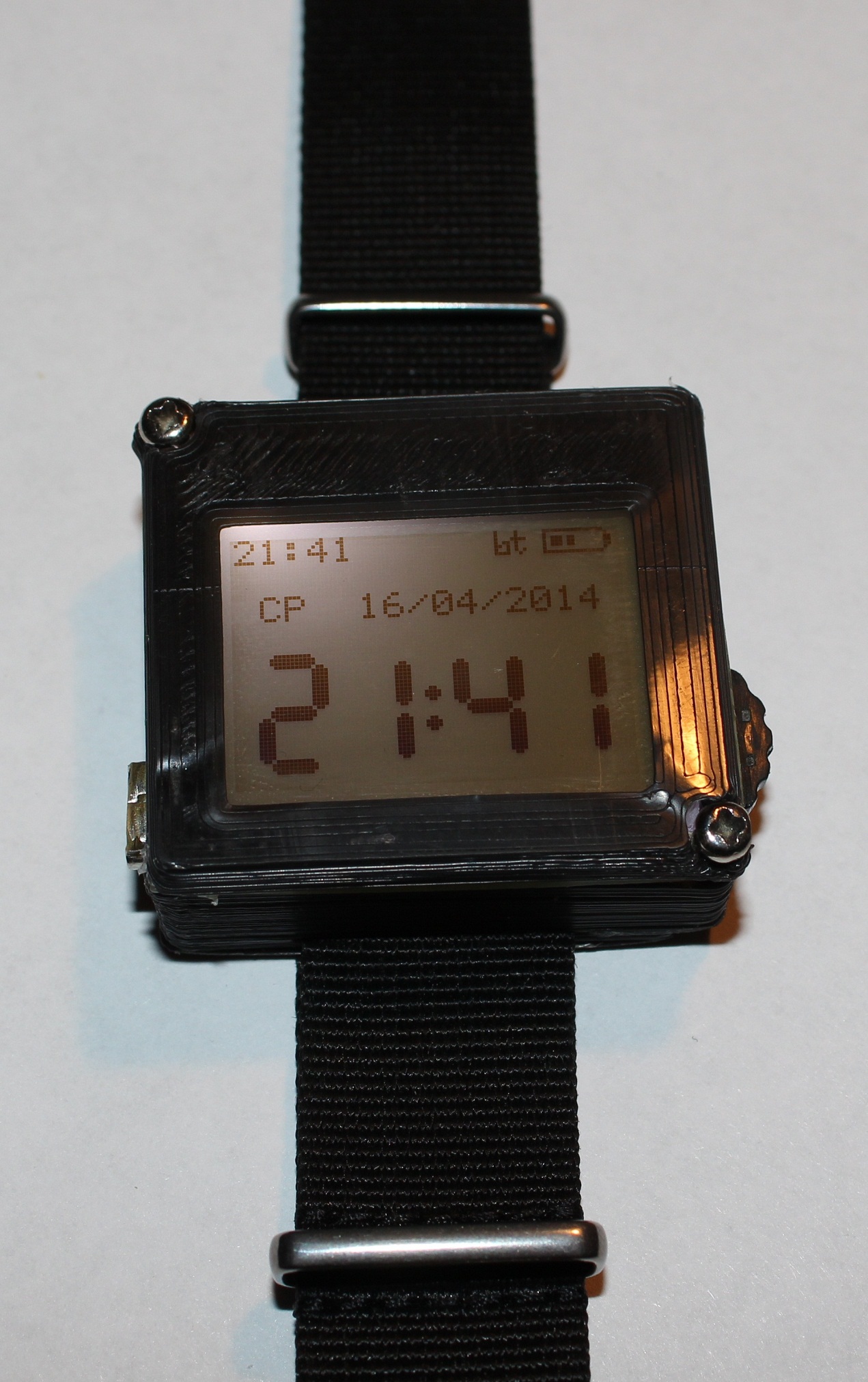
So it's time to put the source code of the MK firmware, but first I want to thank the bigbee for the new case for my watch, which he printed and sent me for free. Also, thanks to Chameleonka for the offer to print the case.
So, the program was written in Code Compmser Studio V 5.3.0
I will not paint the code thoroughly, but I will sign the important points (in my opinion).
Just want to make a reservation that this program is not perfect and is not optimized.
Let's get started
')
The program includes a file Symbols.h, containing a table of characters, icons of the notification panel, numbers for hours. All data is presented in the form of arrays that store data for pixel-by-pixel display on the screen.
Also included is the file TI_USCI_I2C_master.h. This is the standard library from TI for working with the USCI module as an I2C master for receiving and transmitting data.
Inclusions and definitions
#include <msp430g2553.h> #include "Symbols.h" #include "TI_USCI_I2C_master.h" /* Bit operations */ #define BIT_SET(lval, mask) ((lval) |= (mask)) #define BIT_CLR(lval, mask) ((lval) &= ~(mask)) #define BIT_TEST(val, mask) (((val) & (mask))==(mask)) /* BSL */ #define TXD BIT1 // P1.1: BSL TxD #define RXD BIT5 // P1.5: BSL RxD /* BT */ #define BT_TXD BIT1 // P2.1: UART BT TxD #define BT_RXD BIT0 // P2.0: UART BT RxD #define BT_PWR BIT2 // P2.2, P3.2 #define BT_LED BIT3 // P3.3 /* LCD */ #define PIN_RESET BIT2 // P1.2 RESET #define PIN_SCE BIT3 // P1.3 CS #define PIN_SDIN BIT4 // P1.4 SDA //mosi #define PIN_SCLK BIT1 // P3.1 SCK #define PIN_LED BIT0 // P3.0 #define LCD_C 0 // Command #define LCD_D 1 // Data /* Buttons & vibro */ #define B_CENT BIT4 // P2.4 #define B_UP BIT3 // P2.3 #define B_DOWN BIT5 // P2.5 #define vibro BIT4 // P3.4 /* System configuration */ #define TIMER1A_CLOCK 1000000L // Timer1_A clock rate (1 MHz) #define UART_BAUD 9600 // desired UART baud rate #define BT_BITTIME (TIMER1A_CLOCK/UART_BAUD) // Bit interval #define BT_HALF_BT ((BT_BITTIME+1)/2) // Half-bit interval #define Slave_Address 0x68 // address RTC Definition of functions
void check_akkum(void); // void check_bluetooth(void); // BT void uart_tx_bt(char c); // BT void uart_puts_bt(char const* s); // BT void get_time_from_rtc(void); // FLASH void set_time_to_rtc(void); // void LcdCharacter(char character); // void LcdClear(void); // void clear_1(void); // , void Lcd_set_pos(unsigned char c, unsigned char r); // void Lcd_set_pos_pix(unsigned char c, unsigned char r); // void lcd_contrast(unsigned char contrast2); // void lcd_dig(unsigned char num, unsigned char pos_x, unsigned char pos_y); // void lcd_dot(unsigned char num, unsigned char pos_x, unsigned char pos_y); // void LcdWrite(unsigned char dc, unsigned char data); // / void LcdString(char *characters); // void lcd_show_sms(unsigned char a); // void lcd_show_call(unsigned char a); // void lcd_show_bt(unsigned char a); // BT void lcd_show_bat(unsigned char proc); // void lcd_set_time_big(void); // void lcd_set_time_small(void); // ( ) void lcd_show_main(void); // ( ) void menu_setting(unsigned char submenu); // void down_sub_menu(void); // void up_sub_menu(void); // void parse_string(void); // Configure the MK modules to work with external clock modules:
- DCO - Built-in frequency 8MHz;
- Timer0 - PWM for display backlighting;
- Timer1 - Software UART to communicate with BT;
- WDT + - Interval timer for checking hours;
- FLASH - Storage of changeable settings and date / time;
- ADC10 - ADC for determining the voltage on the battery.
Initialization
WDTCTL = WDTPW + WDTHOLD; // // init clocks BCSCTL1 = CALBC1_8MHZ; DCOCTL = CALDCO_8MHZ; BCSCTL2 = 0; // MCLK = 8MHz/1,SMCLK = 8MHz/1 BCSCTL3 = LFXT1S_2; // Mode 2 for LFXT1 : VLO = 12kHz __delay_cycles(800000); // BSL . 0 BIT_SET(P1DIR, TXD | RXD); BIT_CLR(P1OUT, TXD | RXD); edit_time = 0; // FLASH' char *a; a = (char*) 0x104d; contrast = *a++; pwm_width = 0x00ff | (*a++) << 8; timer_off = ((*a++) & 0x00ff) << 8; timer_off |= ((*a++) & 0x00ff); // LCD BIT_SET(P1DIR, PIN_RESET + PIN_SCE + PIN_SDIN); BIT_SET(P3DIR, PIN_SCLK); BIT_CLR(P1OUT, PIN_RESET + PIN_SDIN); BIT_CLR(P3OUT, PIN_SCLK); BIT_SET(P1OUT, PIN_SCE); BIT_SET(P3DIR, PIN_LED); BIT_SET(P3OUT, PIN_LED); BIT_SET(P1OUT, PIN_RESET); // LCD LcdWrite(LCD_C, 0xE2); // LcdWrite(LCD_C, 0x3D); // Charge pump ON LcdWrite(LCD_C, 0x01); // Charge pump=4 LcdWrite(LCD_C, 0xA4); // LcdWrite(LCD_C, 0x2F); // LcdWrite(LCD_C, 0xC0); // - LcdWrite(LCD_C, 0xA0); // - __delay_cycles(800000); LcdWrite(LCD_C, 0xAF); // Display ON LcdClear(); lcd_contrast(contrast); BIT_SET(P3SEL, PIN_LED); BIT_SET(P3DIR, PIN_LED); // TACTL = TASSEL_2 + ID_0 + MC_1 + TACLR; // SMCLK/1 + TACCR0 + counter clear TACCR0 = 0x0fff; // TACCR2 = pwm_width; // TACCTL2 = OUTMOD_6; // // init Bluetooth BIT_SET(P3DIR, BT_PWR); BIT_CLR(P3REN, BT_PWR); BIT_SET(P3OUT, BT_PWR); BIT_SET(P2DIR, BT_PWR); BIT_CLR(P2REN, BT_PWR); BIT_SET(P2OUT, BT_PWR); // ON BIT_CLR(P3DIR, BT_LED); // bt_on = 1; lcd_show_bt(1); //Timer1 uart TA1CTL = TASSEL_2 + ID_3 + MC_2 + TAIE; //SMCLK/8 + Continous up + interrupt enable TA1CCTL1 = OUT; //Tx TA1CCTL0 = CM_2 + SCS + CAP + CCIE; //Rx // Rx TX BIT_SET(P2SEL, BT_TXD + BT_RXD); BIT_SET(P2DIR, BT_TXD); // . BIT_SET(TA1CCTL2, CCIE); // BIT_CLR(P2DIR, B_CENT|B_UP|B_DOWN); // - IN BIT_SET(P2REN, B_CENT|B_UP|B_DOWN); // BIT_SET(P2IE, B_CENT|B_UP|B_DOWN); // BIT_SET(P2IES, B_CENT|B_UP|B_DOWN); // 1/0 (/) BIT_CLR(P2IFG, B_CENT|B_UP|B_DOWN); // // WDT+ , 12 - ACLK - VLO WDTCTL = WDTPW + WDTTMSEL + WDTSSEL; BIT_SET(IE1, WDTIE); // vibro - BIT_SET(P3DIR, vibro); BIT_CLR(P3OUT, vibro); lcd_show_main(); // __enable_interrupt(); edit_time = 0; get_time = 0; set_time = 0; get_time_from_rtc(); // __delay_cycles(8000000); set_time_to_rtc(); // // init ADC ADC10CTL0 = SREF_1 + ADC10SR + REF2_5V + ADC10SHT_2 + REFON + ADC10ON + ADC10IE; ADC10CTL1 = INCH_0; ADC10AE0 |= 0x01; // 0- Interruptions
All interrupt handlers first disable other interrupts, which are turned back on when the handler ends.
When receiving data via BT, either Timer1 is interrupted if the clock is in active mode, or P2 if the clock is in power saving mode.
In LPM3 mode, SMCLK is disabled, respectively, the timer does not work. If the P2 port is interrupted from BT, we transfer the MC to the active mode and translate the BT_RXD pin to the Timer1 input.
At the end of data reception (the end of message symbol 0x00), the received string is processed. The first character of the string is an identifier. “1” - the phone connected to the clock; "2" - incoming SMS; “3” - incoming call; "4" - the text that you just need to display the clock; “5” - date and time sent from the phone.
Parse string
unsigned int il; unsigned char z,k; switch (inputString[0]) { case '1': { // BT BIT_SET(P3OUT, vibro); __delay_cycles(1600000); BIT_CLR(P3OUT, vibro); __delay_cycles(1600000); BIT_SET(P3OUT, vibro); __delay_cycles(1600000); BIT_CLR(P3OUT, vibro); __delay_cycles(1600000); BIT_SET(P3OUT, vibro); __delay_cycles(1600000); BIT_CLR(P3OUT, vibro); lcd_show_bt(2); bt_connect = 1; break; } case '2': { // current_screen = 1; lcd_show_sms(1); lcd_show_call(0); clear_1(); Lcd_set_pos(0, 1); z = 1; il = 1; k = 15; if (multiscreen) { current_screen = 4; while (il < 105) { LcdCharacter(inputString[il]); if (++il > k){ Lcd_set_pos(0, ++z); k += 15; } } LcdCharacter(0x7f); } else while (inputString[il] != 0x00) { LcdCharacter(inputString[il]); if (++il > k){ Lcd_set_pos(0, ++z); k += 15; } } BIT_SET(P3OUT, vibro); __delay_cycles(2800000); BIT_CLR(P3OUT, vibro); __delay_cycles(2400000); BIT_SET(P3OUT, vibro); __delay_cycles(8000000); BIT_CLR(P3OUT, vibro); break; } case '3': { // current_screen = 1; lcd_show_sms(0); lcd_show_call(1); clear_1(); Lcd_set_pos(0, 2); il = 1; z = 2; k = 15; while (inputString[il] != 0x00) { LcdCharacter(inputString[il]); if (++il > k){ Lcd_set_pos(0, ++z); k += 15; } } call_true = 1; BIT_SET(P3OUT, vibro); __delay_cycles(1600000); BIT_CLR(P3OUT, vibro); __delay_cycles(800000); BIT_SET(P3OUT, vibro); __delay_cycles(8000000); BIT_CLR(P3OUT, vibro); __delay_cycles(1600000); BIT_SET(P3OUT, vibro); __delay_cycles(1600000); BIT_CLR(P3OUT, vibro); __delay_cycles(800000); BIT_SET(P3OUT, vibro); __delay_cycles(8000000); BIT_CLR(P3OUT, vibro); break; } case '4': { // current_screen = 1; lcd_show_sms(0); lcd_show_call(0); clear_1(); Lcd_set_pos(0, 1); il = 1; z = 1; k = 15; if (multiscreen) { current_screen = 4; while (il < 105) { LcdCharacter(inputString[il]); if (++il > k){ Lcd_set_pos(0, ++z); k += 15; } } LcdCharacter(0x7f); } else while (inputString[il] != 0x00) { LcdCharacter(inputString[il]); if (++il > k){ Lcd_set_pos(0, ++z); k += 15; } } break; } case '5': { // edit_time = 1; s10 = inputString[1] & 0x0f; s1 = inputString[2] & 0x0f; m10 = inputString[3] & 0x0f; m1 = inputString[4] & 0x0f; h10 = inputString[5] & 0x0f; h1 = inputString[6] & 0x0f; dw = (inputString[7] & 0x0f) + 1 ; d10 = inputString[8] & 0x0f; d1 = inputString[9] & 0x0f; mo10 = inputString[10] & 0x0f; mo1 = inputString[11] & 0x0f; ye10 = inputString[14] & 0x0f; ye1 = inputString[15] & 0x0f; set_time = 1; break; } default: { break; } } if (!multiscreen) for (il = 313; il > 0; il--) inputString[il] = 0; The P2 interrupt handler also checks for button presses. If the button is pressed, it exits the power saving mode. Also, for each button in the P2 interrupt handler, there is a “long” pressing test cycle.
WDT + interrupt handler checks the status of BT, gives the command to update the time from the RTC, gives the command to turn on the ADC.
The ADC10 interrupt handler issues a command to update the battery status. The ADC10 interrupt is triggered after the conversion is completed.
Work with FLASH
// FLASH char *Flash_ptrC; Flash_ptrC = (char *) 0x1040; // Point to beginning of seg C FCTL2 = FWKEY + FSSEL_1 + FN1; // MCLK/3 for Flash Timing Generator FCTL1 = FWKEY + ERASE; // Set Erase bit FCTL3 = FWKEY ; // Clear LOCK *Flash_ptrC = 0x00; // Dummy write to erase Flash seg C FCTL1 = FWKEY + WRT; // Set WRT bit for write operation Flash_ptrC = (char *) 0x1040; // Point to beginning *Flash_ptrC++ = s10; // 0x1040 *Flash_ptrC++ = s1; // 0x1041 *Flash_ptrC++ = m10; // 0x1042 *Flash_ptrC++ = m1; // 0x1043 *Flash_ptrC++ = h10; // 0x1044 *Flash_ptrC++ = h1; // 0x1045 *Flash_ptrC++ = dw; // 0x1046 *Flash_ptrC++ = d10; // 0x1047 *Flash_ptrC++ = d1; // 0x1048 *Flash_ptrC++ = mo10; // 0x1049 *Flash_ptrC++ = mo1; // 0x104a *Flash_ptrC++ = ye10; // 0x104b *Flash_ptrC++ = ye1; // 0x104c *Flash_ptrC++ = contrast; // 0x104d *Flash_ptrC++ = (pwm_width & 0xff00) >> 8; // 0x104e *Flash_ptrC++ = (timer_off & 0xff00) >> 8; // 0x104f *Flash_ptrC++ = (timer_off & 0x00ff); // 0x1050 FCTL1 = FWKEY; // Clear WRT bit FCTL3 = FWKEY + LOCK; // Set LOCK // FLASH char *a; a = (char*) 0x1040; s10 = *a++; s1 = *a++; m10 = *a++; m1 = *a++; h10 = *a++; h1 = *a++; dw = *a++; d10 = *a++; d1 = *a++; mo10 = *a++; mo1 = *a++; ye10 = *a++; ye1 = *a++; contrast = *a++; pwm_width = 0x00ff | (*a++) << 8; timer_off = ((*a++) & 0x00ff) << 8; timer_off |= ((*a++) & 0x00ff); Sources of the program here
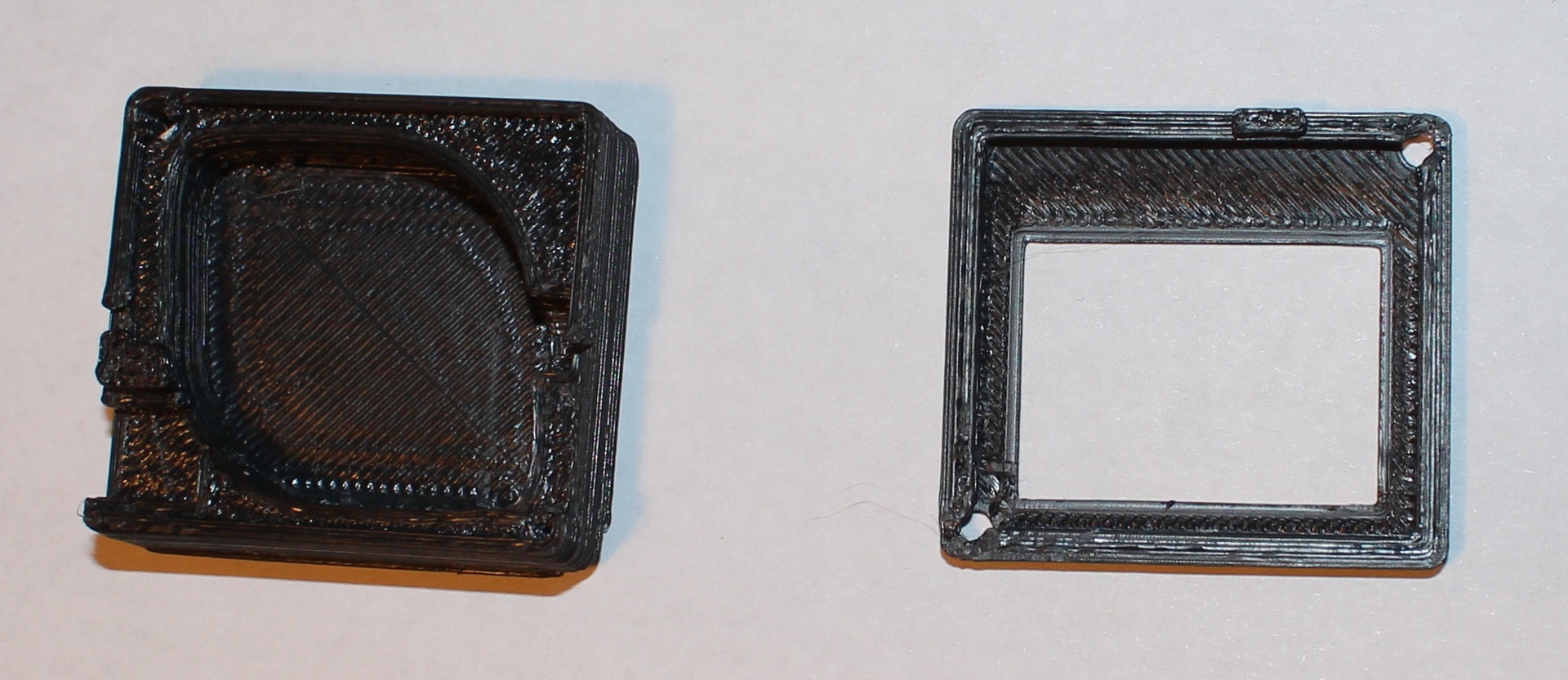
And another photo of the new body:

As always, I look forward to questions and comments.
Part 1 - Start
Part 2 - Board and Components
Source: https://habr.com/ru/post/219773/
All Articles