Suspend the CD, or a practical example of modeling based on OpenSCAD for 3D printing

In this article I would like to share the experience of using the free program OpenSCAD, for 3D modeling of the figure provided in the picture.
It will be shown step by step all the way of modeling and finished, printed 3D detail at the end.
')
With this part, you can hang the cd-disk on a string. There are not so many benefits for humanity of the planet, but thanks to the solution of this hobby problem I (for the first time) tried OpenSCAD, and in half an hour “from scratch” I drew a 3D model.
OpenSCAD is a free and open program for 3D modeling, but unlike other 3D programs, the mouse is used only to view the finished part, and the drawing itself is based on the compiled program in the OpenSCAD language.
The essence of the program in the OpenSCAD language is quite simple - in it we give commands for drawing geometric primitives, over which we can perform the operations of rotation, movement, scaling. And with a plus to this we can carry out “arithmetic” commands on figures, for example, addition, subtraction.
A simple illustration of the idea:
10 10 And we get the following result:

Installing OpenSCAD
To install, download the version for your OS from the official site (http://www.openscad.org/). At the moment, the version from 03.2014 .
After the start of the program we will see 2 areas:

Left - to enter the program in the OpenSCAD language,
Right - the result of the drawing.
To draw the program, you must press F5 , for full rendering - F6 .
I note that when opening a file - it is not necessary to edit it in the OpenSCAD environment, you can edit it in your favorite text editor, for drawing in the open version when editing with an external editor - you must press F4 .
Hello world
Let's try to draw a cube :
cube();We write in the left text zone (10 is the side of the cube):
cube(10); Note that each line in the program ends with a semicolon .
Press F5, we can see on the right - the cube - we can rotate it by capturing it with the mouse, use the roller to increase / decrease, and the right button to move the viewing point.

And try to draw a sphere , the command:
sphere(10) cube(10); sphere(10); View the result F5:

Now add the subtraction command :
difference() { OBJ1; OBJ2;} difference() { OBJ1; OBJ2;} .Commands are written as a function call, if there are no parameters, then empty brackets, and then those objects or objects to which this function should be applied.
This is what subtraction will look like.
difference(){ cube(10); sphere(10); } And here is the result:
I think the basics are clear.
Now back to our main task.
Suspension simulation
To make the CD hang on a thread, in a horizontal position:
- There must be something where you can fix the thread
- The disc must rely on something
- The thread attachment point should be in the center of the disk, when viewed from above, and should be above the plane when viewed from the side
Let's start with the attachment point of the thread, or rather what is between it and the base of the disk.
Cross modeling
I decided to perform this fragment in the form of a cross, which goes up like a truncated pyramid.
Ok, at the beginning we make a cross.
To do this, draw two rectangular parallelepipeds, perpendicular to each other.
Note : for simplicity of the text - I will call “rectangular parallelepiped” - “cuboid”, that is, this is a variation of the cube.
When drawing shapes, by default they go from the center, to the positive sides of the X, Y, Z axes. This can be seen in our first example - and the cube was drawn in the positive zone (whereas the sphere is initially drawn in the center of coordinates).
But there is an option when the center of the drawn figure will be in the center of coordinates. To do this, use the attribute
center = true .The time has come to think about the size. The diameter of the internal hole of the CD - 15 mm. So the bottom of the cross should be no more than 15 mm, for the stock we take 14 mm.
The first part of the cross:
cube([14,1,15], center=true); Happened:

If we specify each wall of the "cube", then we should use the record
[x, y, z] , the second parameter (center = true), we indicated that the "cuboid" will be drawn in the center of coordinates.We have indicated:
14 is the width of the “cuboid” - it should be no more than 15 mm - the inner hole of the CD-ROM disk.
1 - wall thickness
15 is the height of the “cuboid”, since it is in the center of Z, then in the upper part there will be 15/2 = 7.5 mm - this will be the height to the point of attachment.
Next, we need the second part of the cross, for this we need to turn the same “cuboid” 90 degrees, relative to the Z axis.
The rotation function looks like:
rotate(a = deg, v = [x, y, z]) { ... }Where in the parameters of the function the angle of rotation (a) is indicated, and the vector (v) relative to which the rotation takes place.
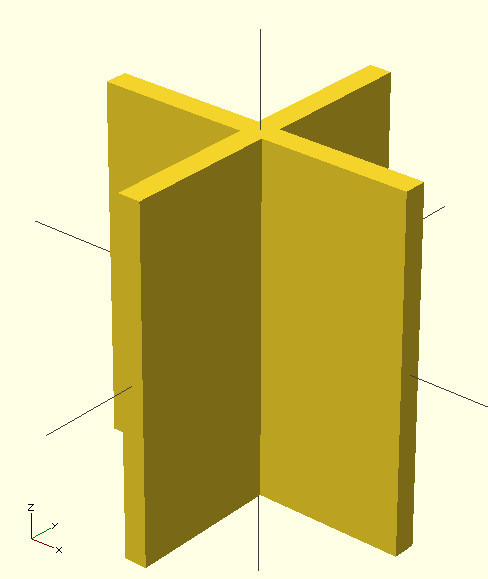
This is how the program will look like:
cube([14,1,15], center=true); rotate(a=90, v=[0,0,1]){ cube([14,1,15], center=true); } And the result
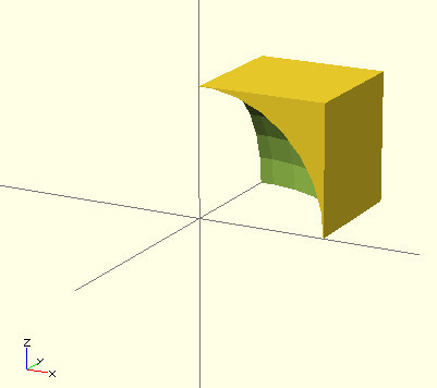
Now we need to remove the extra part that is under the zero plane (below).
To do this, we can draw the bottom of the cube, and subtract it from our figure. But the cube will be drawn in the center, we need to move it down.
The move command looks like this:
translate(v = [x, y, z]) { ... }Where the parameters indicate the vector (v) to which the object must be moved (specified in the function body).
We draw a cube with a side of 15 mm, and move it down by 15/2 mm (yes, you can specify mathematical operations) - it turns out to be completely under the plane.
Here is the updated code:
cube([14,1,15], center=true); rotate(a=90, v=[0,0,1]){ cube([14,1,15], center=true); } translate(v=[0,0,-15/2]){ cube(15, center=true); } And here is the result:

Now we use the command of subtraction already known to us - we need to subtract from the cross, a cube. But the problem is - to subtract two objects are needed - we have three - two “cuboids” (cross), and a cube.
To do this, use the merge command :
union(){ OBJ1; OBJ2; ... } union(){ OBJ1; OBJ2; ... } union(){ OBJ1; OBJ2; ... } .It turns out the following code (with union and subtraction):
difference(){ union(){ cube([14,1,15], center=true); rotate(a=90, v=[0,0,1]){ cube([14,1,15], center=true); } } translate(v=[0,0,-15/2]){ cube(15, center=true); } } Result

The cross turned out, now we need to make it pyramidal.
For this purpose, we would have approached a cone, and the operation of "intersection" when there remains only that part of the figures, which coincides in both figures.
But the commands for drawing a cone are not in OpenSCAD.
But there is a cylinder drawing command :
cylinder(h = 10, r = 10, [r2 = 20,]);where besides the basic two parameters (for getting a cylinder) - the base radius [r] and the height [f] is the third [r2] - the vertex radius, with which you can draw a cone if set to 0. Or a truncated cone - if you set the value not equal to the base radius.
That's what we need.
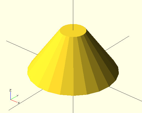
We will determine the size, the base of the cone in diameter should be 14, that is, the radius 7. Height 15/2 mm. Let the radius of the upper base be 1mm, the size itself will be 2mm, we will place an eyelet for it on it.
We will draw a cone in the center of coordinates, so it will be necessary to lift it up halfway up (15/4).
Fragment:
translate(v=[0,0,7/2]){ cylinder(h=7, r=7, r2=2, center=true); } Here is what it looks like:
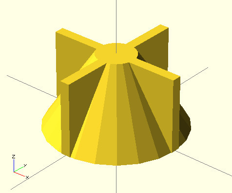
Result code:
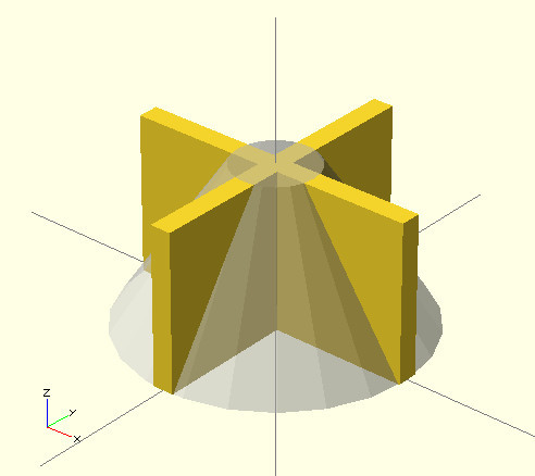
difference(){ union(){ cube([14,1,15], center=true); rotate(a=90, v=[0,0,1]){ cube([14,1,15], center=true); } } translate(v=[0,0,-15/2]){ cube(15, center=true); } } translate(v=[0,0,15/4]){ cylinder(h=15/2, r=7, r2=2, center=true); } And the result:
Note that because of the drawn cone, we do not see what is inside. In OpenSCAD, it is possible for the view mode to make the selected figures translucent, for this it is necessary at the beginning of the line, before the command add "%".
Here is the code:
difference(){ union(){ cube([14,1,15], center=true); rotate(a=90, v=[0,0,1]){ cube([14,1,15], center=true); } } translate(v=[0,0,-15/2]){ cube(15, center=true); } } %translate(v=[0,0,15/4]){ cylinder(h=15/2, r=7, r2=2, center=true); } And what happens:
Ok, now we need to get the intersection of our crosses and cones.
Intersection command :
intersection() { OBJ1; OBJ2; ...} intersection() { OBJ1; OBJ2; ...}Add to our code:
intersection(){ difference(){ union(){ cube([14,1,15], center=true); rotate(a=90, v=[0,0,1]){ cube([14,1,15], center=true); } } translate(v=[0,0,-15/2]){ cube(15, center=true); } } translate(v=[0,0,15/4]){ cylinder(h=15/2, r=7, r2=2, center=true); } } And we get the result:
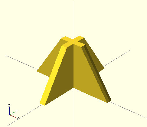
Stand for mounting the thread is ready.
Further it will be easier, we draw an eyelet for the thread.
Modeling the eyelet for the thread
Ear - it will be a little ring. We will create it by subtracting flat cylinders.
To do this, we draw a cylinder, whose height will be equal to the thickness of the ear, inside it we draw a smaller cylinder, and subtract it from the larger one. Further, what turned out is rotated 90 degrees around the y axis, and lifted up to the top of our cross.
Here is the code snippet:
translate(v=[0,0,15/2]){ rotate(a=90, v=[1,0,0]){ difference(){ cylinder(h=1, r=2, center=true); cylinder(h=1, r=1, center=true); } } } And the result
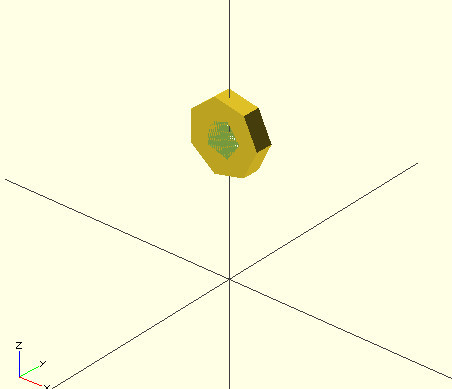
Here is this in the code of our program:
intersection(){ difference(){ union(){ cube([14,1,15], center=true); rotate(a=90, v=[0,0,1]){ cube([14,1,15], center=true); } } translate(v=[0,0,-15/2]){ cube(15, center=true); } } translate(v=[0,0,15/4]){ cylinder(h=15/2, r=7, r2=2, center=true); } } translate(v=[0,0,15/2]){ rotate(a=90, v=[1,0,0]){ difference(){ cylinder(h=1, r=2, center=true); cylinder(h=1, r=1, center=true); } } } And here is the result:
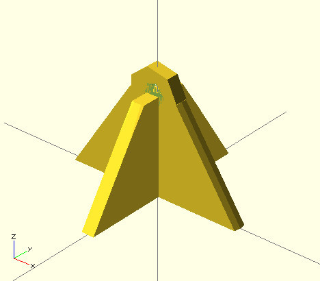
That is, there is a mount for the thread, now we need to make a base for the CD.
Disc base
We will act slyly - we will not draw it. We will use the Rafts.
What is Raft?
Raft (raft) is a technical substrate, which generates a program for 3D printing, it is a way to increase the adhesion of the printed 3D figures.
This is what the Raft looks like, in fact, it is a mesh below:
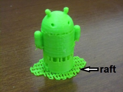
The raft is automatically calculated according to the contour of the base of the figure, and it is indented around, as a rule, 5 mm.
We just need it - the substrate, the layer under our figure will provide support for the CD.
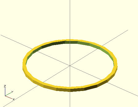
Base ring
The only subtlety is that the raft will be in the shape of a cross, but this is easy to fix - we will draw a thin ring at the bottom.
We draw two cylinders, with a height of 0.5 mm, an outer diameter of 14 mm, that is, a radius of 7 mm, an inner radius of 6.5 mm, and subtract - we get a ring, lift it up to 0.25 (since we drew in the center of coordinates).
Here is the fragment code:
translate(v=[0,0,0.25]){ difference(){ cylinder(h=0.5, r=7, center=true); cylinder(h=0.5, r=6.5, center=true); } } Result:
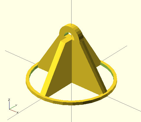
And here is the final drawing code :
intersection(){ difference(){ union(){ cube([14,1,15], center=true); rotate(a=90, v=[0,0,1]){ cube([14,1,15], center=true); } } translate(v=[0,0,-15/2]){ cube(15, center=true); } } translate(v=[0,0,15/4]){ cylinder(h=15/2, r=7, r2=2, center=true); } } translate(v=[0,0,15/2]){ rotate(a=90, v=[1,0,0]){ difference(){ cylinder(h=1, r=2, center=true); cylinder(h=1, r=1, center=true); } } } translate(v=[0,0,0.25]){ difference(){ cylinder(h=0.5, r=7, center=true); cylinder(h=0.5, r=6.5, center=true); } } System variables
Possibly noted - that the circles are “angular”, to increase the number of segments for drawing circles, you can set the parameter (at the very beginning of the code):
$fn=30; Then it will be more beautiful:
STL generation
Finally!
Now, do not forget to press F6 , for rendering. And in the menu File -> Export -> Export as STL ... , the STL file is saved.
Now we load the received STL into the 3D printing program, do not forget to set the Raft option in the settings (5 mm).
This is what Cura looks like:
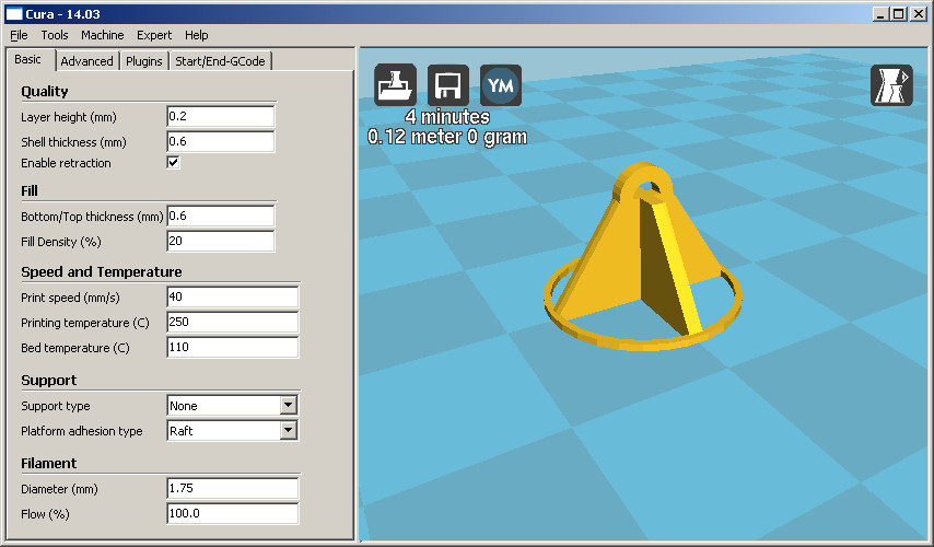
And we start printing.
Result
Here is the detail in action:

And here is our raft:

As a conclusion
This is of course the most basic features of OpenSCAD (the possibilities of creating its functions, the use of variables were not considered), but even they are enough to make a 3D model relatively quickly.
If you do not know where to perform 3D printing in your city, you can do:
- search in hackspaces in your city, as a rule there are 3d printers, and they are available for small orders
- You can search for a fab lab, there should also be a 3d printer
- search service 3d printing (in your city)
Download model
Modelka and code can be downloaded from Thingiverse .
Source: https://habr.com/ru/post/219601/
All Articles