Threshold decoder
Hello friends!
A couple of months ago, I began to talk about the noise-immune coding methods. The first article was devoted to the Chase algorithm. She is here . Many were interested in this direction, so I decided to continue. The next step is a very curious, promising, and importantly simple to understand threshold decoder. Let's start!
The threshold decoder provides an extremely simple decoding based on the principle of "majority voting".
An encoder is a register queue filled with bits of a vector that needs to be encoded. Processing begins at zero cell. For a bit located in the zero cell, the necessary characteristics are calculated, and the bits that have left the queue are moved to the end of the queue, to the twelfth cell, and can be used to calculate the necessary data for the bit located in the zero cell. The coding mechanism will work until all the bits of the original vector are in the zero cell. In front of the encoder is a key that has two positions. In the first position, the key skips the bits from the channel to the register until the register is full. After the register is filled, the key is transferred to the state two, encoding begins, and bits from the last (12th) cell of the register fall into the zero cell, after calculating the characteristics necessary for them.

It can be said that the presented coder is defined using the “generator polynomial” g (x) = 1 + x + x ^ 4 + x ^ 6.
Thus, with the encoding process, two parts of the encrypted message will be received, which later will be combined and transmitted to the channel as a single vector. The first - informational (u) will contain the bits of the original message transmitted to the straight line from the zero cell of the register of the message being encoded. The second is that the check (v) will contain bits obtained by adding bits from register cells with indices corresponding to nonzero powers of the “generating polynomial” g (x).
')
Suppose we need to encrypt the following message: 0111011011011. The information branch (u) will fully correspond to the original message, i.e. will be equal to "1101101101110".
The check branch (v) will consist of bits obtained by adding “modulo two” bits, from the 0th, 1st, 4th, and 6th cells of the register.
Example:
1. In the register: 1 0 1 1 1 0 1 1 0 1 1 0 1
V = 1 ⊕ 0 ⊕ 1 1 = 1;
2. In the register: 1 1 0 1 1 1 0 1 1 0 1 1 0
V = 1 ⊕ 1 ⊕ 1 ⊕ 0 = 1;
......
13. In the register: 0 1 1 1 0 0 1 0 1 1 0 1 1
V = 0 ⊕ 1 ⊕ 0 ⊕ 1 = 0;
After the "circle" of the encoder, the test part will be a vector: "111000000010".
Therefore, the vector “1011101101101111000000001010” will be sent to the channel.
It should be noted that the format of the vector [u | v] is not the only correct one. And it can be easily replaced with any other format, for example: [u1 | v1 | u2 | v2 ... un | vn]
Consider the operation of the threshold decoder. At the first step of the decoder operation, with the help of the coder included in it, the check bits are calculated, for the information bits received from the channel of the branch u, it is added “modulo two” with the accepted check bits from the branch v. As a result, a syndrome is formed in the syndrome register, which indicates the presence of errors. In front of the encoder register, a key is located in the decoder, which works similarly to the key in the encoder. In the first position, it “lets in” the bits from the channel to the encoder, and after the start of decoding, the bits coming from the twelfth cell of the encoder register are sent to the zero cell. The key in front of the syndrome register works similarly. The only difference is that in the first state, it skips the bits into the register not immediately from the channel, but from the adder located in front of the key.
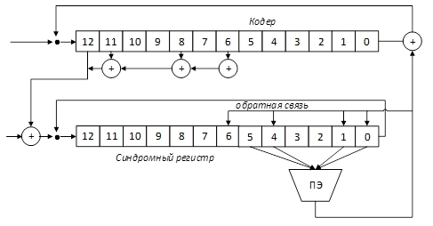
After the syndrome register is filled, the information symbol is decoded from the 0th cell, for which the sum of the syndrome register elements corresponding to the symbol being decoded is compared in the threshold element (PE). In the event that the sum is greater than the threshold, the PE output is set to 1, which leads to a change in the information symbol and related checks. Otherwise, PE will be 0.
The considered decoder is a decoder with feedback, since the correction in the information register, the error is also removed from the syndrome register due to feedback.
Let the error message “10111 1 1101101 1110000000010” be entered into the original message “10111011011011110000000010”.
The syndrome register will contain the following values: "00000011001010" (the very first bit is the cell "0" of the syndrome register in the picture)
1. In the syndrome register: “0000011001010” → “0000011001010”
At the threshold: 1, 1 <2 → no changes. The result is the value "1";
2. In the syndrome register: “0000110010100” → “0000110010100”
At the threshold 1, 1 <2 → no changes. The result is the value "1";
......
6 In the syndrome register: “1100101000000” → “0000000000000”.
At the threshold of 4, 4> 2 → there is a change. The result is the value "0", changes are made in the syndrome;
As a result, after decoding, we will receive the message "1 1 0 1 1 0 1 1 0 1 1 1 0". The error has been fixed. And after the inversion of the positions of all bits, we get the original message "0 1 1 1 0 1 1 0 1 1 0 1 1".
The threshold decoder is a successful combination of ease of implementation, efficiency and speed. Its development is a multithreshold decoder. Tell about which I will try in the near future.
Thank you all who read. I will be glad to constructive comments / comments. I tried to be intelligible :)
A couple of months ago, I began to talk about the noise-immune coding methods. The first article was devoted to the Chase algorithm. She is here . Many were interested in this direction, so I decided to continue. The next step is a very curious, promising, and importantly simple to understand threshold decoder. Let's start!
How does it work
The threshold decoder provides an extremely simple decoding based on the principle of "majority voting".
An encoder is a register queue filled with bits of a vector that needs to be encoded. Processing begins at zero cell. For a bit located in the zero cell, the necessary characteristics are calculated, and the bits that have left the queue are moved to the end of the queue, to the twelfth cell, and can be used to calculate the necessary data for the bit located in the zero cell. The coding mechanism will work until all the bits of the original vector are in the zero cell. In front of the encoder is a key that has two positions. In the first position, the key skips the bits from the channel to the register until the register is full. After the register is filled, the key is transferred to the state two, encoding begins, and bits from the last (12th) cell of the register fall into the zero cell, after calculating the characteristics necessary for them.
It can be said that the presented coder is defined using the “generator polynomial” g (x) = 1 + x + x ^ 4 + x ^ 6.
Thus, with the encoding process, two parts of the encrypted message will be received, which later will be combined and transmitted to the channel as a single vector. The first - informational (u) will contain the bits of the original message transmitted to the straight line from the zero cell of the register of the message being encoded. The second is that the check (v) will contain bits obtained by adding bits from register cells with indices corresponding to nonzero powers of the “generating polynomial” g (x).
')
Encoder example
Suppose we need to encrypt the following message: 0111011011011. The information branch (u) will fully correspond to the original message, i.e. will be equal to "1101101101110".
The check branch (v) will consist of bits obtained by adding “modulo two” bits, from the 0th, 1st, 4th, and 6th cells of the register.
Example:
1. In the register: 1 0 1 1 1 0 1 1 0 1 1 0 1
V = 1 ⊕ 0 ⊕ 1 1 = 1;
2. In the register: 1 1 0 1 1 1 0 1 1 0 1 1 0
V = 1 ⊕ 1 ⊕ 1 ⊕ 0 = 1;
......
13. In the register: 0 1 1 1 0 0 1 0 1 1 0 1 1
V = 0 ⊕ 1 ⊕ 0 ⊕ 1 = 0;
After the "circle" of the encoder, the test part will be a vector: "111000000010".
Therefore, the vector “1011101101101111000000001010” will be sent to the channel.
It should be noted that the format of the vector [u | v] is not the only correct one. And it can be easily replaced with any other format, for example: [u1 | v1 | u2 | v2 ... un | vn]
Decoder operation
Consider the operation of the threshold decoder. At the first step of the decoder operation, with the help of the coder included in it, the check bits are calculated, for the information bits received from the channel of the branch u, it is added “modulo two” with the accepted check bits from the branch v. As a result, a syndrome is formed in the syndrome register, which indicates the presence of errors. In front of the encoder register, a key is located in the decoder, which works similarly to the key in the encoder. In the first position, it “lets in” the bits from the channel to the encoder, and after the start of decoding, the bits coming from the twelfth cell of the encoder register are sent to the zero cell. The key in front of the syndrome register works similarly. The only difference is that in the first state, it skips the bits into the register not immediately from the channel, but from the adder located in front of the key.
After the syndrome register is filled, the information symbol is decoded from the 0th cell, for which the sum of the syndrome register elements corresponding to the symbol being decoded is compared in the threshold element (PE). In the event that the sum is greater than the threshold, the PE output is set to 1, which leads to a change in the information symbol and related checks. Otherwise, PE will be 0.
The considered decoder is a decoder with feedback, since the correction in the information register, the error is also removed from the syndrome register due to feedback.
Let the error message “10111 1 1101101 1110000000010” be entered into the original message “10111011011011110000000010”.
The syndrome register will contain the following values: "00000011001010" (the very first bit is the cell "0" of the syndrome register in the picture)
1. In the syndrome register: “0000011001010” → “0000011001010”
At the threshold: 1, 1 <2 → no changes. The result is the value "1";
2. In the syndrome register: “0000110010100” → “0000110010100”
At the threshold 1, 1 <2 → no changes. The result is the value "1";
......
6 In the syndrome register: “1100101000000” → “0000000000000”.
At the threshold of 4, 4> 2 → there is a change. The result is the value "0", changes are made in the syndrome;
As a result, after decoding, we will receive the message "1 1 0 1 1 0 1 1 0 1 1 1 0". The error has been fixed. And after the inversion of the positions of all bits, we get the original message "0 1 1 1 0 1 1 0 1 1 0 1 1".
Epilogue
The threshold decoder is a successful combination of ease of implementation, efficiency and speed. Its development is a multithreshold decoder. Tell about which I will try in the near future.
Thank you all who read. I will be glad to constructive comments / comments. I tried to be intelligible :)
Source: https://habr.com/ru/post/219159/
All Articles