We make the management of "smart home" via the Internet in a couple of minutes
Good day. Many of us, including me, have long had the idea of creating their own “Smart Home”. But it was postponed due to the great complexity of implementation from both the hardware and software side, which required its creator to be a “guru” in many areas.
In this article I will tell you about a very simple and quite functional way to manage the smart home system via the Internet. On its creation in the presence of the necessary components will take just a few minutes.
')
Intrigued? I ask under the cat.
One day, roaming the Internet in search of information about “Smart Homes,” came across an interesting video where a man in a white coat showed how to manage ARDUINO via the Internet. Later it turned out that this man is one of the developers of the project on kickstarter.com called Ninja Blocks.
Here, that same video.
Ninja Blocks is a very interesting and quite successful project that offers control and control of large peripherals of home devices using their module (which they offer to buy for 199 enemy units). The module interacts with the cloud, through which the device is managed. There are also applications for iOS and Android with the help of which management is also possible.
Ninja Blocks developers were not too lazy and wrote their library for ARDUINO for which many thanks!
The cloud is not quite simple, it not only sends and receives data, it is also programmable by the user who creates the so-called RULES. Thus, the cloud becomes an online “brain” of the “Smart Home”.
FOR EXAMPLE: when you press a button, the cloud waits for 30 seconds, and then turns on a relay, waits another 60 seconds and turns it off.
Rules are easily created from the control panel.
To repeat his example, Ethetnet Shield was needed. At that time, I had at my disposal a module based on enc28j60. But no matter how I tried to repeat the example using different libraries, nothing happened. A module compatible with the native Ethernet library for ARDUINO, i.e. based on the w5100 chip. Shield was ordered from heaven and everything was postponed for a long month.
If you have already watched the video above, you will understand what we need:
- compatible ARDUINO board
- w5100 thernet shield
- account on a.ninja.is
- different small things in the form of resistors, buttons and LEDs
So. The fee has come. All collected, connected, downloaded.
It was amazing, but it all worked)) But there is always “BUT”. Literally a couple of minutes noticed that the LED stopped responding to control through the site. Rebooting the controller helped, but only for the same couple of minutes. At the same time, the button always worked in parallel. Yes, it was a serious problem with which the "Smart Home" does not build.
After studying this example, several questions arose:
1. How to manage multiple devices receiving data (LEDs)?
2. How to add several devices sending data (button, temperature sensor)?
3. How to fix the control for the LEDs through the panel, which “falls off” after a couple of minutes?
The search began with a not very popular section on the developer forum called ARDUINO. A solution was found to correct the problem with the management. One of the forum participants finalized the project library. The most amazing thing is that for half a year the developers have not updated the library on github. Apparently they fear competition for themselves from projects based on Arduino)).
Below you can download the already corrected library.
A few hours of experimentation and study of the blurred explanations of the developers on the forum and library gave their fruits. All questions were successfully resolved ... =)
And so now in the case.
Library for Arduino is engaged only in receiving and sending data.
The main parameter in the data is the device ID to which the server accesses or from which it receives information. View the full list here. ninjablocks.com/pages/device-ids Each ID has its own widget in the control panel.
In the Serial Monitor, sending or receiving a single command or data looks like this:
Now consider what's inside.
“G”: “0” - the GUID parameter indicates the sequence number within the group of devices with the same ID. For example, 3 temperature sensors with the same ID = 1 are installed. Then for the first sensor the GUID will be 0, for the second one - 1 and 2 for the third.
"V": 0 - the VID parameter is an identifier for devices as well as an ID.
“D”: 1 — The DID (Device ID) parameter indicates the type of device. For example, the temperature sensor has ID = 1 or 31, button - 5.
“GUID”: “ETHERSHIELDBLOCK_0_0_1” - it's hard to say why this is necessary, but in general it contains the name of the ARDUINO block (which can be changed at the beginning of the example from the library) and all the above perechischennye parameters.
"DA": 27 - well, the data itself, which we transmit. For a button or a relay, this is 0 or 1, for an RGB LED it is a color code such as FFFFFF.
Conventionally, all sensors and devices can be divided into two types. The first type only transmit information (button, temperature and humidity sensor). And the second type only accept it. Here lies one nuance. The control panel does not initially know what is connected to the controller. And if the first type itself will inform about itself, when they will transmit data and the panel will immediately create for them, depending on their ID. So for the second type you need to create widgets in the control panel by sending data.
How to send data from multiple devices with the same ID.
Everything is very simple before each sending data, we must specify the sequence number of the device (GUID)
When receiving data for several devices with the same ID, we need to check what the GUID is.
Let's return to devices of the second type. To create a widget in the control panel, it’s enough just to send data on its behalf. Create a widget with an ON / OFF switch for each of the two LEDs by writing the following in a void setup loop:
After receiving this data, the panel will create a widget for them.
Now I bring to your attention a simple program for working with Ninja Blocks.
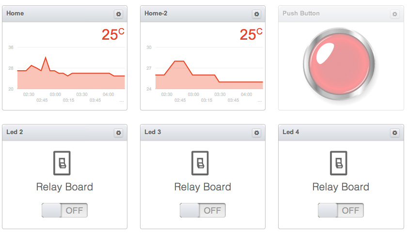
- Manages 4th LEDs
- Sends the testimony of 2 ds18b20 temperature sensors with an interval of 60 seconds
- Every 20 seconds synchronizes the position of the ON / OFF switches with the status of the LEDs. Since the control panel does not monitor in any way whether the data reached the controller and therefore it sometimes happens that the ON position on the panel and in fact the output is turned off. This method allows you to set the switches in the panel to the correct position every 20 seconds if they were not right before.
- A button is connected, when clicked, the programmed script is executed.
I tried to provide the code with detailed comments.
Prepared a small demo video
Let's summarize a little.
Advantages:
- Management and control from anywhere in the world (if there is an Internet)
- It is assembled and configured in minutes.
- very simple and inexpensive
- Availability of special scenarios
- A wide list of widgets in the control panel.
- If you add a TP-Link TL-MR3020 router ($ 20) and a 3G modem, then you can use it in the country and other places without the Internet.
- If there is no desire to pull the network cable, then it is enough to buy TP-Link TL-WR702N for $ 15, which will work as a wi-fi shield
- Good stability at work. For 2 days of testing, not a single team was lost, everything works clearly.
Disadvantages:
- The main disadvantage of this system is the impossibility of working without the Internet.
- There is a delay when switching on varies from a fraction of a second to several
- The library eats a lot of space - as much as 16 KB, if you add a library for nrf24l01, then almost nothing remains. You'll have to switch to Mega most likely.
- The application for smartphones does not allow viewing sensor readings. Device management is not very convenient, you can not see the current on / off status.
Future plans:
- Add a connection test in the code and in case of its absence, the Arduino will act independently and will reboot the TP-Link TL-MR3020 and 3G modem if it works in conjunction with them.
- Add nrf24l01 to control and monitor other sensors.
It is very interesting to hear your opinion and constructive criticism. Original questions are welcome! Fuh ...
FILES:
Corrected library.
PS During operation, the w5100 chip on the Etherten Shield is very hot to a temperature of about 45-50 degrees. This is normal?
Find out the current temperature of my Shield here .
In this article I will tell you about a very simple and quite functional way to manage the smart home system via the Internet. On its creation in the presence of the necessary components will take just a few minutes.
')
Intrigued? I ask under the cat.
One day, roaming the Internet in search of information about “Smart Homes,” came across an interesting video where a man in a white coat showed how to manage ARDUINO via the Internet. Later it turned out that this man is one of the developers of the project on kickstarter.com called Ninja Blocks.
Here, that same video.
Ninja Blocks is a very interesting and quite successful project that offers control and control of large peripherals of home devices using their module (which they offer to buy for 199 enemy units). The module interacts with the cloud, through which the device is managed. There are also applications for iOS and Android with the help of which management is also possible.
Ninja Blocks developers were not too lazy and wrote their library for ARDUINO for which many thanks!
The cloud is not quite simple, it not only sends and receives data, it is also programmable by the user who creates the so-called RULES. Thus, the cloud becomes an online “brain” of the “Smart Home”.
FOR EXAMPLE: when you press a button, the cloud waits for 30 seconds, and then turns on a relay, waits another 60 seconds and turns it off.
Rules are easily created from the control panel.
To repeat his example, Ethetnet Shield was needed. At that time, I had at my disposal a module based on enc28j60. But no matter how I tried to repeat the example using different libraries, nothing happened. A module compatible with the native Ethernet library for ARDUINO, i.e. based on the w5100 chip. Shield was ordered from heaven and everything was postponed for a long month.
If you have already watched the video above, you will understand what we need:
- compatible ARDUINO board
- w5100 thernet shield
- account on a.ninja.is
- different small things in the form of resistors, buttons and LEDs
So. The fee has come. All collected, connected, downloaded.
It was amazing, but it all worked)) But there is always “BUT”. Literally a couple of minutes noticed that the LED stopped responding to control through the site. Rebooting the controller helped, but only for the same couple of minutes. At the same time, the button always worked in parallel. Yes, it was a serious problem with which the "Smart Home" does not build.
After studying this example, several questions arose:
1. How to manage multiple devices receiving data (LEDs)?
2. How to add several devices sending data (button, temperature sensor)?
3. How to fix the control for the LEDs through the panel, which “falls off” after a couple of minutes?
The search began with a not very popular section on the developer forum called ARDUINO. A solution was found to correct the problem with the management. One of the forum participants finalized the project library. The most amazing thing is that for half a year the developers have not updated the library on github. Apparently they fear competition for themselves from projects based on Arduino)).
Below you can download the already corrected library.
A few hours of experimentation and study of the blurred explanations of the developers on the forum and library gave their fruits. All questions were successfully resolved ... =)
And so now in the case.
Library for Arduino is engaged only in receiving and sending data.
The main parameter in the data is the device ID to which the server accesses or from which it receives information. View the full list here. ninjablocks.com/pages/device-ids Each ID has its own widget in the control panel.
In the Serial Monitor, sending or receiving a single command or data looks like this:
{"GUID": "ETHERSHIELDBLOCK_0_0_1","G": "0","V": 0,"D": 1,"DA": 27} Now consider what's inside.
“G”: “0” - the GUID parameter indicates the sequence number within the group of devices with the same ID. For example, 3 temperature sensors with the same ID = 1 are installed. Then for the first sensor the GUID will be 0, for the second one - 1 and 2 for the third.
"V": 0 - the VID parameter is an identifier for devices as well as an ID.
“D”: 1 — The DID (Device ID) parameter indicates the type of device. For example, the temperature sensor has ID = 1 or 31, button - 5.
“GUID”: “ETHERSHIELDBLOCK_0_0_1” - it's hard to say why this is necessary, but in general it contains the name of the ARDUINO block (which can be changed at the beginning of the example from the library) and all the above perechischennye parameters.
"DA": 27 - well, the data itself, which we transmit. For a button or a relay, this is 0 or 1, for an RGB LED it is a color code such as FFFFFF.
Conventionally, all sensors and devices can be divided into two types. The first type only transmit information (button, temperature and humidity sensor). And the second type only accept it. Here lies one nuance. The control panel does not initially know what is connected to the controller. And if the first type itself will inform about itself, when they will transmit data and the panel will immediately create for them, depending on their ID. So for the second type you need to create widgets in the control panel by sending data.
How to send data from multiple devices with the same ID.
Everything is very simple before each sending data, we must specify the sequence number of the device (GUID)
NinjaBlock.guid = "1"; // 0 1-, 1 2- .. NinjaBlock.deviceID=(1); // ID NinjaBlock.send("24"); // When receiving data for several devices with the same ID, we need to check what the GUID is.
if (strcmp(NinjaBlock.strGUID,"1") == 0) // GUID 1 Let's return to devices of the second type. To create a widget in the control panel, it’s enough just to send data on its behalf. Create a widget with an ON / OFF switch for each of the two LEDs by writing the following in a void setup loop:
NinjaBlock.guid = "0"; NinjaBlock.deviceID=(1002); NinjaBlock.send("0"); NinjaBlock.guid = "1"; NinjaBlock.deviceID=(1002); NinjaBlock.send("0"); After receiving this data, the panel will create a widget for them.
Now I bring to your attention a simple program for working with Ninja Blocks.
- Manages 4th LEDs
- Sends the testimony of 2 ds18b20 temperature sensors with an interval of 60 seconds
- Every 20 seconds synchronizes the position of the ON / OFF switches with the status of the LEDs. Since the control panel does not monitor in any way whether the data reached the controller and therefore it sometimes happens that the ON position on the panel and in fact the output is turned off. This method allows you to set the switches in the panel to the correct position every 20 seconds if they were not right before.
- A button is connected, when clicked, the programmed script is executed.
Program code
#include <SPI.h> #include <Ethernet.h> #include <NinjaBlockEthernet.h> //#include <MemoryFree.h> #define DEFAULT_VENDOR_ID 0 // ID #define LED_DEVICE_ID 1002 // ID 2- #define BUTTON_DEVICE_ID 5 // ID #define TEMP_ID 1 // ID #include <OneWire.h> #include <DallasTemperature.h> // ds18b20 #define ONE_WIRE_BUS 2 // 2 #define ENABLE_SERIAL false // serial monitor byte button = 5; byte led_1 = 7; byte led_2 = 6; byte led_3 = 4; byte led_4 = 3; boolean isButtonDown = false; int time =500; // int timeup=500; // OneWire oneWire(ONE_WIRE_BUS); DallasTemperature sensors(&oneWire); void setup(){ sensors.begin(); // pinMode(button, INPUT); // pinMode(led_1, OUTPUT); pinMode(led_2, OUTPUT); pinMode(led_3, OUTPUT); pinMode(led_4, OUTPUT); #if ENABLE_SERIAL Serial.begin(9600); Serial.println("Starting.."); #endif delay(1000); // This delay is to wait for the Ethernet Controller to get ready NinjaBlock.host = "api.ninja.is"; NinjaBlock.port = 80; NinjaBlock.nodeID = "ETHERSHIELDBLOCK"; // NinjaBlock.token = " "; // Get yours from https://a.ninja.is/hacking NinjaBlock.guid = "0"; NinjaBlock.vendorID=DEFAULT_VENDOR_ID; NinjaBlock.deviceID=LED_DEVICE_ID; NinjaBlock.deviceID=TEMP_ID; if (NinjaBlock.begin()==0) // NinjaBlock.guid = "0"; // 2- 1- NinjaBlock.deviceID=(1002); NinjaBlock.send("0"); NinjaBlock.guid = "1"; // 2- NinjaBlock.deviceID=(1002); NinjaBlock.send("0"); NinjaBlock.guid = "2"; // 3- NinjaBlock.deviceID=(1002); NinjaBlock.send("0"); NinjaBlock.guid = "3"; // 4- NinjaBlock.deviceID=(1002); NinjaBlock.send("0"); } void loop() { // // if ( timeup == 1) // ( 20 ) { if( digitalRead(led_1)== HIGH) // 1 { NinjaBlock.guid = "0"; // NinjaBlock.deviceID=(1002); // ID NinjaBlock.send("1"); // 1 , } if(digitalRead(led_1)== LOW) // 1 , 0 { NinjaBlock.guid = "0"; NinjaBlock.deviceID=(1002); NinjaBlock.send("0"); Serial.println( " Led-1 OFF UPdate"); } if(digitalRead(led_2)== HIGH) { NinjaBlock.guid = "1"; NinjaBlock.deviceID=(1002); NinjaBlock.send("1"); Serial.println( " Led-2 ON UPdate"); } if(digitalRead(led_2)== LOW) { NinjaBlock.guid = "1"; NinjaBlock.deviceID=(1002); NinjaBlock.send("0"); Serial.println( " Led-2 OFF UPdate"); } if(digitalRead(led_3)== HIGH) { NinjaBlock.guid = "2"; NinjaBlock.deviceID=(1002); NinjaBlock.send("1"); Serial.println( " Led-3 ON UPdate"); } if(digitalRead(led_3)== LOW) { NinjaBlock.guid = "2"; NinjaBlock.deviceID=(1002); NinjaBlock.send("0"); Serial.println( " Led-3 OFF UPdate"); } if(digitalRead(led_4)== HIGH) { NinjaBlock.guid = "3"; NinjaBlock.deviceID=(1002); NinjaBlock.send("1"); Serial.println( " Led-4 ON UPdate"); } if(digitalRead(led_4)== LOW) { NinjaBlock.guid = "3"; NinjaBlock.deviceID=(1002); NinjaBlock.send("0"); Serial.println( " Led-4 OFF UPdate"); } timeup=2000; } // END - // timeup= timeup-1; // delay(1); // // if(NinjaBlock.receive()) { // // // Return values are: // NinjaBlock.strGUID // NinjaBlock.intVID // NinjaBlock.intDID // NinjaBlock.intDATA - if data is integer // NinjaBlock.strDATA - if data is string (note char[64]) if (NinjaBlock.IsDATAString) { //Serial.print("strDATA="); //Serial.println(NinjaBlock.strDATA); if (NinjaBlock.intDID == 1002) // .. ID { if (strcmp(NinjaBlock.strGUID,"0") == 0) // 4- .. GUID { if (strcmp(NinjaBlock.strDATA,"1") == 0) // GUID , { // 1 digitalWrite(led_1, HIGH); } else if (strcmp(NinjaBlock.strDATA,"0") == 0) // 0 - { digitalWrite(led_1, LOW); } } if (strcmp(NinjaBlock.strGUID,"1") == 0) // 2- { if (strcmp(NinjaBlock.strDATA,"1") == 0) { digitalWrite(led_2, HIGH); } else if (strcmp(NinjaBlock.strDATA,"0") == 0) { digitalWrite(led_2, LOW); } } if (strcmp(NinjaBlock.strGUID,"2") == 0) // 3- { if (strcmp(NinjaBlock.strDATA,"1") == 0) { digitalWrite(led_3, HIGH); } else if (strcmp(NinjaBlock.strDATA,"0") == 0) { digitalWrite(led_3, LOW); } } if (strcmp(NinjaBlock.strGUID,"3") == 0) // 4- { if (strcmp(NinjaBlock.strDATA,"1") == 0) { digitalWrite(led_4, HIGH); } else if (strcmp(NinjaBlock.strDATA,"0") == 0) { digitalWrite(led_4, LOW); } } } } } // // if (digitalRead(button) == HIGH) { // if (!isButtonDown) { // #if ENABLE_SERIAL Serial.println("Button Down"); #endif NinjaBlock.guid = "0"; // NinjaBlock.deviceID=5; // ID 5 NinjaBlock.send(1); // 1 - isButtonDown = true; // } } else { if (isButtonDown) { // #if ENABLE_SERIAL Serial.println("Button Up"); #endif NinjaBlock.guid = "0"; // NinjaBlock.deviceID=5; // ID 5 NinjaBlock.send(0); // 0 - isButtonDown = false; // - } } if (time==1) // ( 60 ) { sensors.requestTemperatures(); // Serial.println(sensors.getTempCByIndex(0)); NinjaBlock.guid = "0"; // NinjaBlock.deviceID=(1); // ID NinjaBlock.send(sensors.getTempCByIndex(0)); // Serial.println(sensors.getTempCByIndex(1)); // NinjaBlock.guid = "1"; NinjaBlock.deviceID=(1); NinjaBlock.send(sensors.getTempCByIndex(1)); time=6000; // } time=time-1; // delay (9); } I tried to provide the code with detailed comments.
Prepared a small demo video
Let's summarize a little.
Advantages:
- Management and control from anywhere in the world (if there is an Internet)
- It is assembled and configured in minutes.
- very simple and inexpensive
- Availability of special scenarios
- A wide list of widgets in the control panel.
- If you add a TP-Link TL-MR3020 router ($ 20) and a 3G modem, then you can use it in the country and other places without the Internet.
- If there is no desire to pull the network cable, then it is enough to buy TP-Link TL-WR702N for $ 15, which will work as a wi-fi shield
- Good stability at work. For 2 days of testing, not a single team was lost, everything works clearly.
Disadvantages:
- The main disadvantage of this system is the impossibility of working without the Internet.
- There is a delay when switching on varies from a fraction of a second to several
- The library eats a lot of space - as much as 16 KB, if you add a library for nrf24l01, then almost nothing remains. You'll have to switch to Mega most likely.
- The application for smartphones does not allow viewing sensor readings. Device management is not very convenient, you can not see the current on / off status.
Future plans:
- Add a connection test in the code and in case of its absence, the Arduino will act independently and will reboot the TP-Link TL-MR3020 and 3G modem if it works in conjunction with them.
- Add nrf24l01 to control and monitor other sensors.
It is very interesting to hear your opinion and constructive criticism. Original questions are welcome! Fuh ...
FILES:
Corrected library.
PS During operation, the w5100 chip on the Etherten Shield is very hot to a temperature of about 45-50 degrees. This is normal?
Find out the current temperature of my Shield here .
Source: https://habr.com/ru/post/219107/
All Articles