Accident Alert Info Panel Project (Part 2)
Greetings to all.
The first part examined the concept of the info panel itself, which I collect for the office (where, I recall, normal monitoring of some servers is difficult, including because of the network topology - a gray subnet with some important equipment that does not require access to Internet, but its performance depends on the performance of telephony services, in particular, TDM and E1 ).
Now there is enough material to continue the topic.
Here are the indicators:
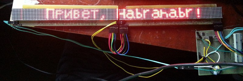
')
At the end of the project will be given all the code with explanations.
The code is distributed under the license WTFPL .
For information on the license, as well as for the code for the Ethernet module ENC28J60 one more thanks to Lifelover .
The project is not finished yet, further there will be a continuation.
Unfortunately, at the moment the device is not yet assembled, and I had to wait quite a bit (during development I encountered unpleasant difficulties both in the manufacture of boards and in the purchase of some consumables).
The display modules are ready (2 of 3), although it is possible to work only with them. Partially assembled "library" of work with the LED-display.
So far there is no interaction interface between the two controllers (here the question is for the habrovans, how to do better - I myself tend to implement through UART)
Who are interested - welcome under cat.
Warning: A lot of photos.
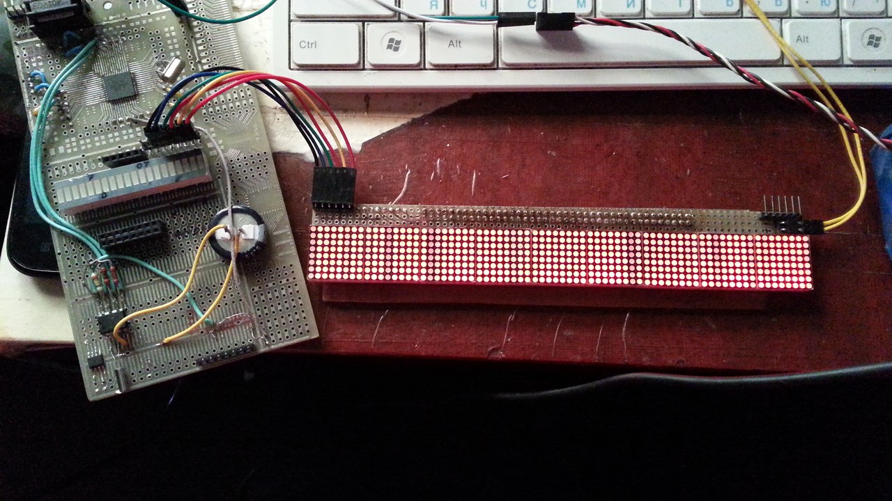
At present, only the module responsible for displaying information on the display works well.
Implemented dynamic display (refresh rate of about 125Hz). The module is controlled from the ATmega48 controller (on the mecket - ATmega1284p ). Both operate at a clock frequency of 12 MHz and 3.3V power (for compatibility with a microSD card and Ethernet module). The power of the display module - should be 5V 0 ~ 2.2A / module, that is, a little more than 10W when the screen is full.
In typical operation (for example, the clock / calendar mode), the device will consume a minimum of power).
At the moment, the issue of nutrition is relevant, but I tend to the option:
48V (PoE) -> 5V (Fly-Back) -> 3.3V (LDO).
The 3.3V power supply circuit should not consume more than 0.5A of current (the Ethernet module’s joint operation (~ 150-250mA) and 2 controllers (hardly more than 20mA), SD cards (did not measure, but hardly more than 50mA), real-time clock (DS1307), although the latter plan to power from 5V through the power filters).
Now two modules of identification are assembled, the same photo as in the title, but without cropping. Photo below.
The overall concept of the device was slightly revised from the first post. Now it will consist of two processors, as usual, Master (ATMefa1284p) and Slave (ATMega48). The CPU board is not ready yet (since the periphery is not completely selected and you do not want to redo everything several times). Now there are some questions about the sound, for example, is it worth bothering to play streaming audio (8bit, ~ 22kHz) directly from the network, or is it easier to drop the idea? The option of reading sound files from an SD card is tempting, but then there is the problem of managing them, as well as (perhaps downloading them to the card directly from the network). Probably, I will stop on the second variant.
The master will be responsible for network support, sound (possibly), as well as (possibly) the simplest telnet access.
Later I will try to implement software update over the network (if straightforward hands are enough), or from an SD card (or rather, uSD in SPI mode). Hands do not reach to assemble breadboard.
Indicator boards a little earlier
There will be 3.
The electronics board is in the process ... until you get rid of it. The photoresist is washed away when developed.
Photos of the next failure: (Now Positiv 20). It seems that this method is not given to me yet.
Initially, a single board with adapters was planned ... it was decided to completely abandon the adapters and switch to something more convenient. Chose a circuit board with wiring. Rough, but it solves the problem.
Electronics board assembly
upd 2014-05-11 : It was possible to win the "driver" of the display, having received a soft scroll of lines across the entire "screen".
On this day, a small victory can be seen here .
I apologize for the link to the VC, but I haven’t yet found another place to upload the video. If someone tells me, I will be grateful.
The second indicator board is being prepared - all the components have already been assembled, it remains to solder the matrices themselves.
The code ... does not tolerate criticism yet, because it will be finished. Although now you can arbitrarily change the dimension of the screen and it will not affect its performance (within reasonable limits).
RAM usage is minimal. Only under the text buffer (or graphics, but 1 frame), and several penemennyh. Fits in available RAM at 512 bytes.
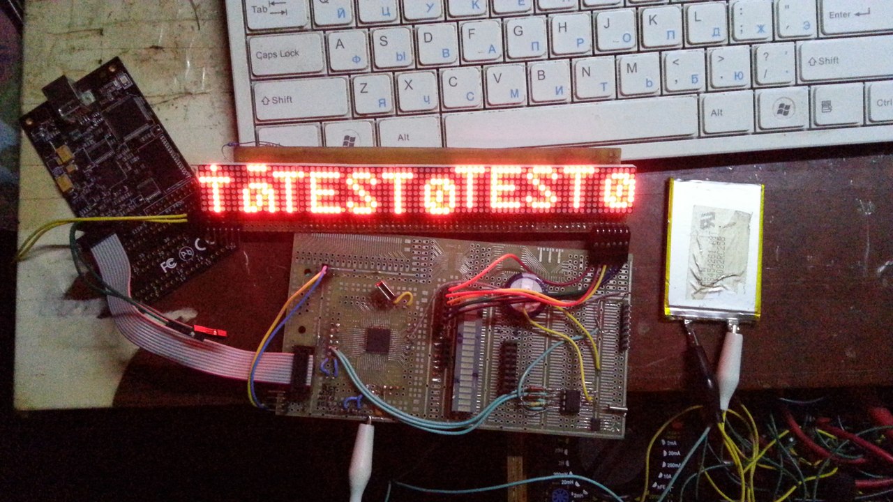
upd 2014-06-02 : Two indicators are ready, the code is scaled to the indicators in a couple of movements - change one define and rebuild the project. The photo was higher.
The control code works, but is not yet sharpened for processing by two controllers. On the breadboard, it works only on one controller, while the second is waiting for its turn. On the 48th mega there is no JTAG, so debugging on hardware will be much more difficult. I try to fix all the bugs before assembling the controller board.
The question arose whether it was possible to update the software of the “neighboring” controller from a flash drive. The most convenient (from the fact that it is easy to connect - microSD / SPI, but you have to write your bootloader). Now I am thinking about the Slave firmware version via the standard ISP interface connected to the Master (I’ll have to output the programming connectors to both controllers, as well as jumpers, so that the Master can update the screen driver software.
Thanks to Alexeyslav for the help on SPI indicator management. This option was considered, but was accidentally forgotten. Now the data is output by the foot-drag method on the controller.
\\ However, it consumes few resources, therefore it is not so fatal.
\\ When I describe the new version - I will try to give the signal plots.
A bit of code:
The first part examined the concept of the info panel itself, which I collect for the office (where, I recall, normal monitoring of some servers is difficult, including because of the network topology - a gray subnet with some important equipment that does not require access to Internet, but its performance depends on the performance of telephony services, in particular, TDM and E1 ).
Now there is enough material to continue the topic.
Here are the indicators:
')
At the end of the project will be given all the code with explanations.
The code is distributed under the license WTFPL .
For information on the license, as well as for the code for the Ethernet module ENC28J60 one more thanks to Lifelover .
The project is not finished yet, further there will be a continuation.
Unfortunately, at the moment the device is not yet assembled, and I had to wait quite a bit (during development I encountered unpleasant difficulties both in the manufacture of boards and in the purchase of some consumables).
The display modules are ready (2 of 3), although it is possible to work only with them. Partially assembled "library" of work with the LED-display.
So far there is no interaction interface between the two controllers (here the question is for the habrovans, how to do better - I myself tend to implement through UART)
Who are interested - welcome under cat.
Warning: A lot of photos.
At present, only the module responsible for displaying information on the display works well.
Implemented dynamic display (refresh rate of about 125Hz). The module is controlled from the ATmega48 controller (on the mecket - ATmega1284p ). Both operate at a clock frequency of 12 MHz and 3.3V power (for compatibility with a microSD card and Ethernet module). The power of the display module - should be 5V 0 ~ 2.2A / module, that is, a little more than 10W when the screen is full.
In typical operation (for example, the clock / calendar mode), the device will consume a minimum of power).
At the moment, the issue of nutrition is relevant, but I tend to the option:
48V (PoE) -> 5V (Fly-Back) -> 3.3V (LDO).
The 3.3V power supply circuit should not consume more than 0.5A of current (the Ethernet module’s joint operation (~ 150-250mA) and 2 controllers (hardly more than 20mA), SD cards (did not measure, but hardly more than 50mA), real-time clock (DS1307), although the latter plan to power from 5V through the power filters).
Now two modules of identification are assembled, the same photo as in the title, but without cropping. Photo below.
Hidden text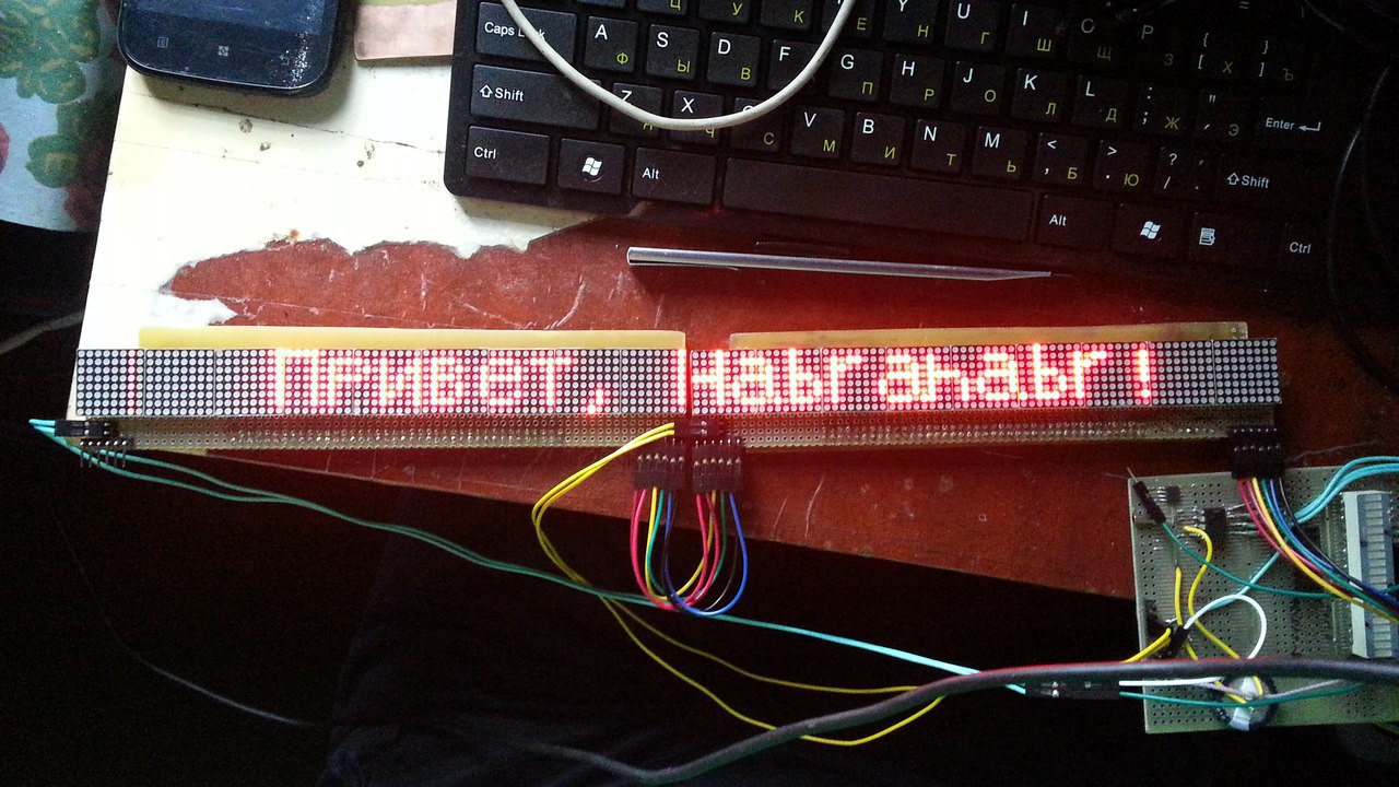 Two display modules have earned together.
Two display modules have earned together.The overall concept of the device was slightly revised from the first post. Now it will consist of two processors, as usual, Master (ATMefa1284p) and Slave (ATMega48). The CPU board is not ready yet (since the periphery is not completely selected and you do not want to redo everything several times). Now there are some questions about the sound, for example, is it worth bothering to play streaming audio (8bit, ~ 22kHz) directly from the network, or is it easier to drop the idea? The option of reading sound files from an SD card is tempting, but then there is the problem of managing them, as well as (perhaps downloading them to the card directly from the network). Probably, I will stop on the second variant.
The master will be responsible for network support, sound (possibly), as well as (possibly) the simplest telnet access.
Later I will try to implement software update over the network (if straightforward hands are enough), or from an SD card (or rather, uSD in SPI mode). Hands do not reach to assemble breadboard.
Indicator boards a little earlier
Hidden text
I know, pretty scary.
I know, pretty scary.
There will be 3.
The electronics board is in the process ... until you get rid of it. The photoresist is washed away when developed.
Photos of the next failure: (Now Positiv 20). It seems that this method is not given to me yet.
Hidden text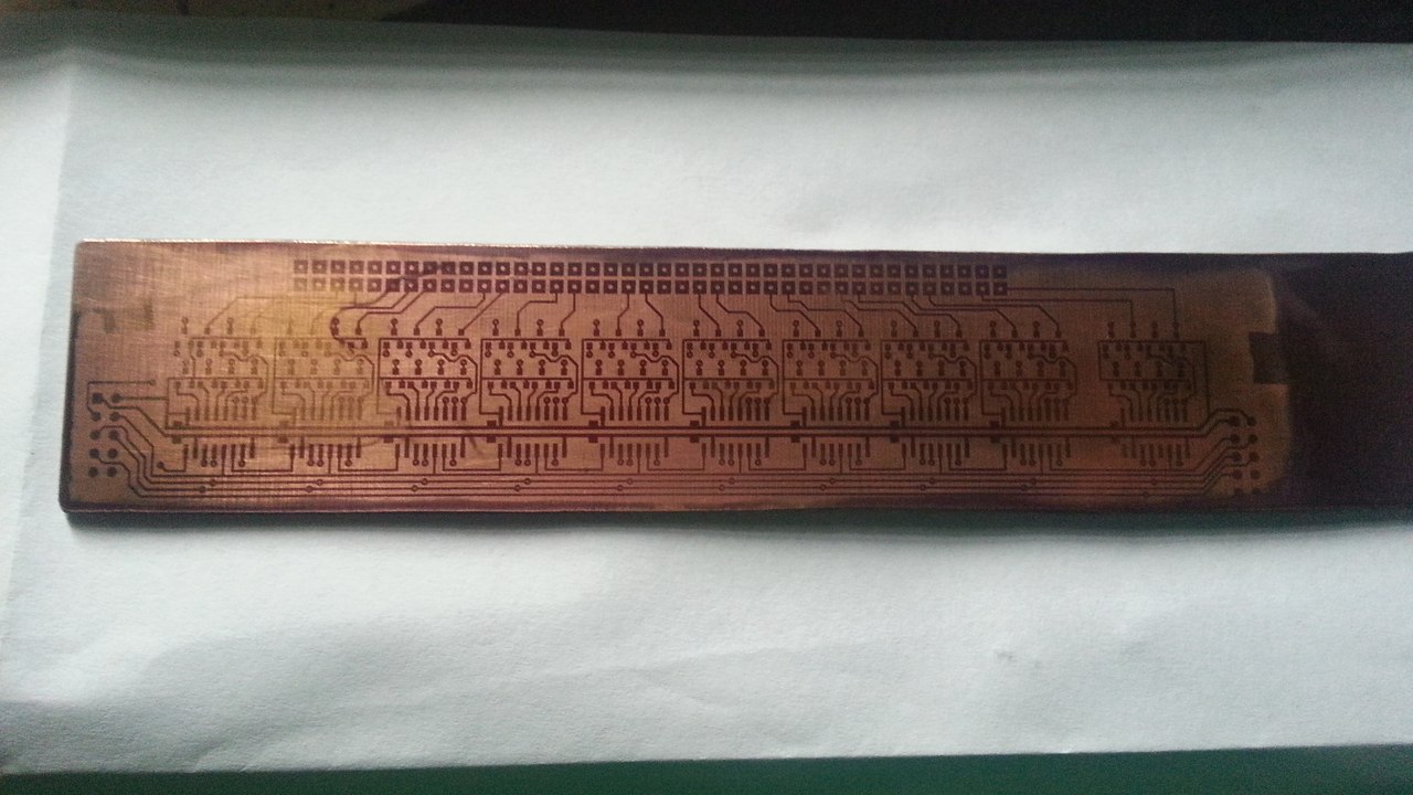
The best thing that has been done so far ... unfortunately, is also damaged. The streaks and uneven layer of resist did their insidious business.
More often it turns out something like this:

Mon-VShch-50 three-year exposure is ... very sad.
The best thing that has been done so far ... unfortunately, is also damaged. The streaks and uneven layer of resist did their insidious business.
More often it turns out something like this:
Mon-VShch-50 three-year exposure is ... very sad.
Initially, a single board with adapters was planned ... it was decided to completely abandon the adapters and switch to something more convenient. Chose a circuit board with wiring. Rough, but it solves the problem.
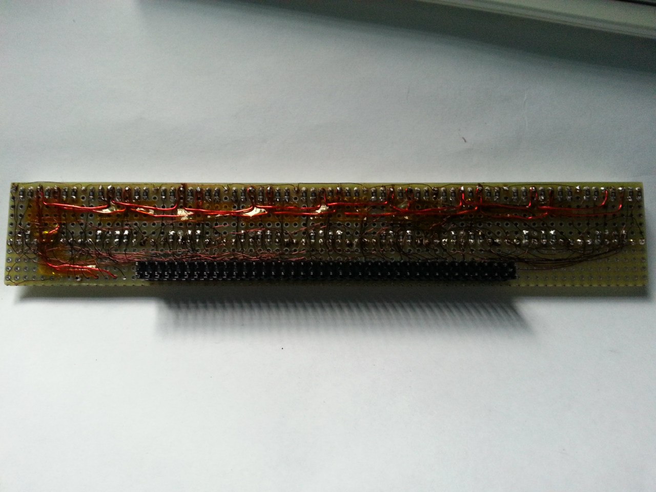
Electronics board assembly
Hidden text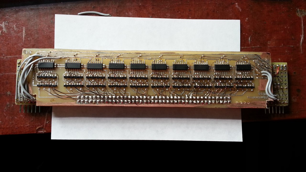
The board itself has already been soldered, an array of indistor keys, shift registers.
Even all the rows and columns work.
In the process of debugging.
For some reason, the string is output with errors. (Obsolete)
The board itself has already been soldered, an array of indistor keys, shift registers.
Even all the rows and columns work.
In the process of debugging.
For some reason, the string is output with errors. (Obsolete)
upd 2014-05-11 : It was possible to win the "driver" of the display, having received a soft scroll of lines across the entire "screen".
On this day, a small victory can be seen here .
I apologize for the link to the VC, but I haven’t yet found another place to upload the video. If someone tells me, I will be grateful.
The code ... does not tolerate criticism yet, because it will be finished. Although now you can arbitrarily change the dimension of the screen and it will not affect its performance (within reasonable limits).
RAM usage is minimal. Only under the text buffer (or graphics, but 1 frame), and several penemennyh. Fits in available RAM at 512 bytes.
upd 2014-06-02 : Two indicators are ready, the code is scaled to the indicators in a couple of movements - change one define and rebuild the project. The photo was higher.
The control code works, but is not yet sharpened for processing by two controllers. On the breadboard, it works only on one controller, while the second is waiting for its turn. On the 48th mega there is no JTAG, so debugging on hardware will be much more difficult. I try to fix all the bugs before assembling the controller board.
The question arose whether it was possible to update the software of the “neighboring” controller from a flash drive. The most convenient (from the fact that it is easy to connect - microSD / SPI, but you have to write your bootloader). Now I am thinking about the Slave firmware version via the standard ISP interface connected to the Master (I’ll have to output the programming connectors to both controllers, as well as jumpers, so that the Master can update the screen driver software.
Thanks to Alexeyslav for the help on SPI indicator management. This option was considered, but was accidentally forgotten. Now the data is output by the foot-drag method on the controller.
\\ However, it consumes few resources, therefore it is not so fatal.
\\ When I describe the new version - I will try to give the signal plots.
A bit of code:
led.h
/* LED AlarmPanel. */ // : (3*9)*8 // 27*8 = 216 . #define MATRIX_COUNT 16 // #define ARRAY_SIZE MATRIX_COUNT * 8 // . #define VisibleChars ARRAY_SIZE / 6 #define LED_MODE_OFF 0 #define LED_MODE_TXT_SCROLL 1 #define LED_MODE_TXT_NO_SCROLL 2 #define LED_MODE_IMG 3 #define LED_MODE_MAX LED_MODE_IMG void LED_Reset(void); // . , . void LED_PushBits(unsigned char DataByte, unsigned char Bits); // . void LED_FirstLine(void); // . void LED_NextLine(void); // ( ) void LED_Sync(void); // "" - , "Latch" . "". //char HEX(unsigned char dataNibble); // // HEX ( [0..15], ). void LED_DrawChar(uint8_t CharN, uint8_t LineNum, /*uint8_t SkipCols,*/ uint8_t ShowCols); // . . (, , ) void LED_DrawString(void); // . 1ms (1000/8 = 125Hz), , 2 (500/8 = 62.5Hz) //void LED_NewString(alarm_packet_t *data); // . , , , . void LED_DrawImg(void); // . , . . // , 8 ( , ). void LED_Poll(void); // , "", . // , , . // . // - . led.c
#include "led.h" //#define TextScrollMS 50 uint8_t DataArray[ARRAY_SIZE]; // . uint8_t CurrMode; // : {0=, 1= , 2= , 3=} uint8_t CurrLength; // ( ). uint8_t CurrLine; // int16_t CurrSkipChars; // // 127 ( 128-), ... int16. uint8_t CurrColSkip; // ( ) volatile uint8_t TextScrollDelayMS; volatile uint16_t LastMS; void LED_SetMode(uint8_t NewMode) { if (NewMode <= LED_MODE_MAX) { CurrMode = NewMode; } else { CurrMode = LED_MODE_OFF; }; }; void LED_Poll(void){ if (CurrMode == LED_MODE_OFF) { return; }; if (CurrMode == LED_MODE_TXT_SCROLL) { LED_DrawString(); }; if (CurrMode == LED_MODE_TXT_NO_SCROLL) { LED_DrawString(); }; if (CurrMode == LED_MODE_IMG) { LED_DrawImg(); }; }; void LED_Reset(void) { char t; CurrLine = 0; CurrSkipChars = -VisibleChars; LED_PORT |= (1<<LED_OE); // Z- LED_PORT |= (1<<LED_DATA_V); // . for (t=0;t<8;t++) { LED_PORT |= (1<<LED_C_V); // 0 LED_PORT &= ~(1<<LED_C_V); // , . }; LED_PORT &= ~(1<<LED_OE); // Z- .. }; void LED_PushBits(unsigned char DataByte, unsigned char Bits) { while (Bits > 0) // { Bits--; // 1 if (DataByte & 0x80) // = 1 ( ) { LED_PORT |= (1<<LED_DATA_H); // "Data" } else { LED_PORT &= ~(1<<LED_DATA_H); // - }; LED_PORT |= (1<<LED_C_H); // LED_PORT &= ~(1<<LED_C_H); // 1 . DataByte <<= 1; // 1. }; // , . }; void LED_FirstLine(void) { LED_PORT &= ~(1<<LED_DATA_V); // LED_PORT |= (1<<LED_C_V); // LED_PORT &= ~(1<<LED_C_V); // . LED_PORT |= (1<<LED_DATA_V); // // LED_Sync(); // }; void LED_NextLine(void) { LED_PORT |= (1<<LED_C_V); // LED_PORT &= ~(1<<LED_C_V); // . CurrLine++; // CurrLine &= 0x07; // 7 // , if (CurrLine==0) { LED_FirstLine(); // , , if (((ticks_count - LastMS) > TextScrollDelayMS)|(ticks_count < LastMS)) { LastMS = ticks_count; // if (CurrMode == LED_MODE_TXT_SCROLL) { CurrColSkip--; // 1 if (CurrColSkip == 255) // , .. { CurrColSkip = 5; // 5/6 ... CurrSkipChars++; // 1 . }; // if (CurrSkipChars > CurrLength) { // (- ) CurrSkipChars = -VisibleChars; }; } else { CurrColSkip = 0; CurrSkipChars = 0; }; }; }; }; void LED_Sync(void) { // LED_PORT |= (1<<LED_OE); // Z- LED_PORT |= (1<<LED_LATCH); // LED_PORT &= ~(1<<LED_LATCH); // . . LED_PORT &= ~(1<<LED_OE); // . . }; void LED_DrawChar(uint8_t CharN, uint8_t LineNum, /*uint8_t SkipCols,*/ uint8_t ShowCols) { unsigned char temp = 0; unsigned char cols; cols = ShowCols; // if (cols == 0) { return; }; if (CharN == 168) { // temp = pgm_read_byte(&CharsRu[65][LineNum]); }; if (CharN == 184) { // temp = pgm_read_byte(&CharsRu[66][LineNum]); }; if (CharN > 191) { // temp = pgm_read_byte(&CharsRu[CharN-192][LineNum]); }; if ((CharN > 32)&(CharN <= 126)) { // temp = pgm_read_byte(&Chars[CharN-32][LineNum]); }; // RAM. , +1 (, 1 .... , ). LED_PushBits(temp, cols); // }; void LED_DrawString(void) { int16_t First; // int16_t Last; // int16_t SymbolsSkip; // // , . uint8_t i; // "i" - 40 ! uint8_t EndedWithChar; // , ... . SymbolsSkip = CurrSkipChars-1; // while (SymbolsSkip < 0) { SymbolsSkip ++; // 0 LED_PushBits(0, 6); // ( ). }; // . // , . if (CurrSkipChars <= 0) // { First = -1; // . } else { First = CurrSkipChars-2; // - -2 // // . }; Last = First + CurrSkipChars + VisibleChars; // . // ( ) if (Last > First) { // , if (Last > CurrLength-1) { // . Last = CurrLength-1; // , . // , ( ) + - - 1 // -1 - , , . SymbolsSkip = VisibleChars + CurrSkipChars - Last - 1; }; if (SymbolsSkip > 0) { EndedWithChar = 0; } else { EndedWithChar = 1; }; // - , , . // 1 ... for (i = First+1; i < Last; i++) { // , . LED_DrawChar(DataArray[i], CurrLine, 6); }; // ... , . if (EndedWithChar) { LED_DrawChar(DataArray[Last], CurrLine, 6-CurrColSkip); } else { LED_DrawChar(DataArray[Last], CurrLine, 6); }; // .. if (SymbolsSkip > 0) { // // ,... for (i=1;i<SymbolsSkip;i++) { // ... . LED_PushBits(0, 6); }; // - - . LED_PushBits(0, 6-CurrColSkip); }; }; LED_Sync(); // . LED_NextLine(); // . }; void LED_DrawImg(void) { uint8_t i; // // - *8 ( ) // . for (i = CurrLine*MATRIX_COUNT; i<CurrLine*(MATRIX_COUNT+1); i++) { // ... , 8 . LED_PushBits(DataArray[i], 8); }; // , MATRIX_COUNT . // . LED_Sync(); // . LED_NextLine(); // . }; Source: https://habr.com/ru/post/218859/
All Articles