Musical toy on STM32 from improvised means
Good afternoon, dear habrovchane.
One evening I got bored and I decided to assemble a small electronic device from components lying around the house, purely for entertainment, without any practical purpose. Anyone can repeat it, even a printed circuit board is not required - the device is assembled from the minimum of electronic components to the canopy, glued with epoxy to some unwanted board, exclusively as a structural element, soldered with the help of wires and flooded with the same epoxy for reliability.
So, do an electronic flute!
In fact, the device is very far from the flute in the spectrum of the sound extracted from it. But he has an RGB-LED that changes color depending on the notes played, and the sounds are made by a piezo-squeaker, thanks to which the flute's consumption is very low.
Let's immediately look at the result:
Component selection
Actually, the device started with the tweeters - I saw among my components a pair of SMD piezo emitters from the company Murata, namely PKLCS1212E4001 and PKLCS1212e2000-r1, similar to it. These are two ordinary piezo emitters of very small dimensions (10 x 12 x 3 mm), one with a peak response in 4000 Hz, the second in 2000 Hz. Unlike the speakers, they consume almost no current, the piezoplate bends when voltage is applied, so a square wave at 4 KHz causes the plate to vibrate at the same frequency, making a loud sound. The consumption is about 0.3 mA at 3.3V.
Since the consumption is so low - why not make a small electronic device powered by a battery? After all, we will not need any amplifiers and powerful current sources. True, it will have to pay for this very curve of the frequency response of the pischalok - no, they can reproduce an arbitrary sound signal, for the experiment I even output WAV to them, but the sound leaves much to be desired, therefore we will “feed” them with the usual meander. And changing its duty cycle will change the volume of the sound.
')

Frequency response tweeters
Here the presence of two different piezo-emitters plays into the hands - in sum, they will give a slightly smoother frequency response and cover a larger frequency range.
So, with a sound emitter, we decided. With the power source, too, no questions - good old CR2032, a lithium battery with a very low level of self-discharge, voltage from 3V (fully charged), up to 2V (fully discharged). For her, I found this convenient SMD holder:

SMD battery holder
Of course, we need a microphone in order to capture external noise, it is the signal from the microphone that will control the duty cycle of a rectangular signal fed to the emitters. Any electret will suit, for example, such :

Electret microphone
Choose a note will be a variable resistor, again, any one will do, but it's better to take a little more resistance so that it does not draw a lot of current from the battery. I took 50 kom.

Variable resistor
You can replace the resistor with several buttons, the game will become much more convenient, but the dimensions of the device will increase (and the number of wires that will have to be led to these buttons, and this, given the chosen method of installation, is a very unpleasant circumstance!)
To make the device more interesting, add an RGB-LED. Of course, this will have a strong effect on consumption, but hardly anyone will play this “flute” long enough for the battery to sit down, so that's okay. I chose the SMD LED KAA-3528EMBSGC .
It remains to the controller - took what was at hand, STM32F100C4 , at one time they were worth almost 20 rubles in Terra for some kind of action, and I could not help myself, I bought them a whole bag. The controller is not in the most convenient case for mounting on the “knee” - LQFP48, with a pitch of 0.5 mm.
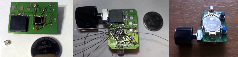
Actually, almost all the details are shown in the photo below (and a piece of some old board to which it all stuck) - a second squeaker was added to them (there is only one in the photo, the one on 4 KHz), a couple of SMD buttons and a handle for potentiometer.

Device details
As for the buttons - initially I planned to select all notes with a variable resistor (and the notes were planned to have two full octaves), but then I realized that then the device would turn out quite uncomfortable and added two buttons. One chooses “sharps”, that is, it shifts the currently selected note a semitone up, and the second shifts the selected note by a whole octave. Thus, instead of 2 (octaves) * 12 (half tones) = 24 positions of the potentiometer, you will need to track only 7, corresponding to seven notes, and change semitones and octaves by pressing the buttons if necessary.
Device layout
Of course, I did not draw the outline of this whole affair, instead using the STM software to select the controller configuration, MicroXplorer. It turned out such a beautiful picture:

So, what and with what we will connect?
- For a start, we need two PWM channels for our two tweeters. In principle, this is a moot point - you can get by with one and put both tweeters in parallel, then they will always feed on the signal of the same frequency and duty cycle.
You can select the channel for each beeper, then the frequencies will be the same, and the duty ratio (and hence the envelope shape!) Can be set individually. And, finally, each timer can be assigned a separate timer, then it will be possible to set different frequencies and different duty cycles.
Since the circuit will be filled with epoxy, after which it will be impossible to change something in it, I decided to output the signals necessary for the implementation of all the options to a small debugging connector in order to be able to change the solution later.
Therefore, we take a timer, say, TIM3, and select a pair of its channels for outputting PWM - these are the pins PA6 and PA7. - Of course, you need three PWM channels to control the RGB LED. Considering the voltage of the battery and its internal resistance, we will feed directly through the pins of the controller, without resistors - we will not give more than 10 mA for each pin, on the blue diode it drops so much that it will not even be able to bring it to maximum brightness at our maximum 3V power supply.
We will derive the fourth channel for the situation mentioned in item 1 - if anything, let them squeak.
So, choose TIM1 and pins PA8, PA9, PA10, PA11 to output PWM. - Definitely have to remove the analog signal from the microphone and potentiometer, for this we use the built-in ADC - pins PA2 and PA3.
Since we started talking about the analog signal, we will immediately think how to take the signal from the microphone. The traditional circuit includes a capacitor, for cutting the DC component, a resistive divider to shift the signal by half the power, the preamp to use the entire dynamic range of the ADC. We will do without all this. We will cut off the constant component programmatically, the dynamic range is not so important to us, therefore we will connect a microphone like this:
As a result, the output will get about 2V in a quiet state, and from ~ 1.5 to ~ 2.5 with loud sounds near the microphone.
The potentiometer, of course, will turn on as a divider between the power supply and the ground, deriving the midpoint to the adjacent ADC channel. - We will need to remove the signal from the two buttons - for this we will use the free pins PA0 and PA1 for now, turn on the internal one, so we just connect the pins through the button to the ground.
- We will definitely need a debugging interface. In principle, it is enough to bring out SWDIO and SWCLK (as well as ground and power), but in reality, the RESET pin will not really, really hurt - since we will set up the sleep mode, we will be left without debug as soon as the controller falls asleep. And it can be changed only by STM utility with a RESET pin, software reset will not work. So let's not play with fire, but just pull out the ground, power, PA13, PA14 pins and NRST pin on the debugger connector.
- The last item is optional, but it makes debugging easier when working with analog signals - we will output the DAC channel to the same connector to which the pins for flashing were brought out - with its help we will be able to watch any intermediate analog signal during processing
That is, in fact, all the iron. Then begins the longest part - the assembly circuit without a printed circuit board. If you are not averse to spending this time fussing with ferric chloride, you can dilute the described scheme on a small board and skip the following points.
Soldering
There is nothing to describe here, I attach a few photos of the process. The microcircuit is glued “upside down”, a thin stripped and debonded wire is soldered to each required leg, and gently retracted to the side. When all the wires are set aside, the connection is checked and, if all is well, the chip is filled with a drop of epoxy. After that, the wires can be pulled without fear. The wire that goes in a ring is the ground, the controller is connected to the ground and to the power supply on each side.

Solder the ground. The old board came in handy - I used its ground to unite the land.

Solder the debugging interface and check that the controller is running.

Solder all other pins

Fill with epoxy

Almost assembled device, it remains to place the second squeaker and top up with epoxy

All is ready
On this, the hardware is finished, go to the firmware.
Firmware
The firmware is pretty simple. We create an empty project under our STM32F100C and begin to prescribe initialization:
GPIO Initialization
#define GPIO_Red GPIO_Pin_9 #define GPIO_Green GPIO_Pin_10 #define GPIO_Blue GPIO_Pin_11 #define GPIO_SHARP GPIO_Pin_0 #define GPIO_OCT GPIO_Pin_1 #define GPIO_FreePWM GPIO_Pin_8 #define GPIO_BUZZER1 GPIO_Pin_6 #define GPIO_BUZZER2 GPIO_Pin_7 void InitGPIO() { GPIO_InitTypeDef GPIO_InitStructure; RCC_APB2PeriphClockCmd(RCC_APB2Periph_GPIOA | RCC_APB2Periph_AFIO, ENABLE); GPIO_InitStructure.GPIO_Pin = GPIO_BUZZER1 | GPIO_BUZZER2 | GPIO_FreePWM |GPIO_Red|GPIO_Green|GPIO_Blue; GPIO_InitStructure.GPIO_Mode = GPIO_Mode_AF_PP; GPIO_InitStructure.GPIO_Speed = GPIO_Speed_50MHz; GPIO_Init(GPIOA, &GPIO_InitStructure); GPIO_InitStructure.GPIO_Pin = GPIO_SHARP | GPIO_OCT; GPIO_InitStructure.GPIO_Mode = GPIO_Mode_IPU; GPIO_InitStructure.GPIO_Speed = GPIO_Speed_10MHz; GPIO_Init(GPIOA, &GPIO_InitStructure); } Here we set up our GPIO - all PWM channels are output controlled by peripherals in the Push-Pull mode (GPIO_Mode_AF_PP), the buttons are input pins pulled to power. ADC channels and so default are configured as analog inputs.
ADC Initialization
#define SIGNAL_OFFSET 850 void InitADC() { ADC_InitTypeDef ADC_InitStructure; RCC_APB2PeriphClockCmd(RCC_APB2Periph_ADC1, ENABLE); ADC_InitStructure.ADC_ScanConvMode = ENABLE; ADC_InitStructure.ADC_ContinuousConvMode = DISABLE; ADC_InitStructure.ADC_ExternalTrigConv = ADC_ExternalTrigConv_None; ADC_InitStructure.ADC_DataAlign = ADC_DataAlign_Right; ADC_Init(ADC1, &ADC_InitStructure); ADC_InjectedSequencerLengthConfig(ADC1, 2); ADC_InjectedChannelConfig(ADC1, ADC_Channel_2, 1, ADC_SampleTime_1Cycles5); ADC_SetInjectedOffset(ADC1, ADC_InjectedChannel_1, SIGNAL_OFFSET); ADC_InjectedChannelConfig(ADC1, ADC_Channel_3, 2, ADC_SampleTime_1Cycles5); ADC_ExternalTrigInjectedConvConfig(ADC1, ADC_ExternalTrigInjecConv_None); ADC_Cmd(ADC1, ENABLE); } Here we set up two ADC channels. We will use it in the “injected channels” mode, which means that we have as many as four registers for the data, that is, we can take up to four measurements from different channels and not care that some data grind others.
We say that we need the SCAN mode - that is, the conversion of all these channels one by one. Channel 2 is responsible for the microphone, so we say that we have an offset of 850 units - this number will automatically be deducted from the result of the conversion. To calculate it, it is enough to set this offset to zero and see what value is removed from the ADC in silence.
Timer initialization
void InitTimers() { RCC_APB1PeriphClockCmd(RCC_APB1Periph_TIM3, ENABLE); RCC_APB2PeriphClockCmd(RCC_APB2Periph_TIM1, ENABLE); TIM_TimeBaseInitTypeDef TIM_TimeBaseStructure; TIM_OCInitTypeDef TIM_OCInitStructure; TIM_TimeBaseStructure.TIM_Period = 0xFFF; TIM_TimeBaseStructure.TIM_Prescaler = 0; TIM_TimeBaseStructure.TIM_ClockDivision = 0; TIM_TimeBaseStructure.TIM_CounterMode = TIM_CounterMode_Up; TIM_TimeBaseInit(TIM3, &TIM_TimeBaseStructure); TIM_OCInitStructure.TIM_OCMode = TIM_OCMode_PWM1; TIM_OCInitStructure.TIM_OutputState = TIM_OutputState_Enable; TIM_OCInitStructure.TIM_Pulse = 0x00; TIM_OCInitStructure.TIM_OCPolarity = TIM_OCPolarity_High; TIM_OC1Init(TIM3, &TIM_OCInitStructure); TIM_OC1PreloadConfig(TIM3, TIM_OCPreload_Enable); TIM_OC2Init(TIM3, &TIM_OCInitStructure); TIM_OC2PreloadConfig(TIM3, TIM_OCPreload_Enable); TIM_SetCompare1(TIM3, 0x00); TIM_SetCompare2(TIM3, 0x00); TIM_ARRPreloadConfig(TIM3, ENABLE); TIM_Cmd(TIM3, ENABLE); TIM_CCxCmd(TIM3, TIM_Channel_1, ENABLE); TIM_CCxCmd(TIM3, TIM_Channel_2, ENABLE); TIM_TimeBaseStructure.TIM_Period = 0xFFF; TIM_TimeBaseStructure.TIM_Prescaler = 0; TIM_TimeBaseStructure.TIM_ClockDivision = 0; TIM_TimeBaseStructure.TIM_CounterMode = TIM_CounterMode_Up; TIM_TimeBaseInit(TIM1, &TIM_TimeBaseStructure); TIM_OCInitStructure.TIM_OCMode = TIM_OCMode_PWM1; TIM_OCInitStructure.TIM_OutputState = TIM_OutputState_Enable; TIM_OCInitStructure.TIM_Pulse = 0x000; TIM_OCInitStructure.TIM_OCPolarity = TIM_OCPolarity_Low; TIM_OC1Init(TIM1, &TIM_OCInitStructure); TIM_OC2Init(TIM1, &TIM_OCInitStructure); TIM_OC3Init(TIM1, &TIM_OCInitStructure); TIM_OC4Init(TIM1, &TIM_OCInitStructure); TIM_CCxCmd(TIM1, TIM_Channel_1, DISABLE); TIM_CCxCmd(TIM1, TIM_Channel_2, ENABLE); //R TIM_CCxCmd(TIM1, TIM_Channel_3, ENABLE); //G TIM_CCxCmd(TIM1, TIM_Channel_4, ENABLE); //B TIM_Cmd(TIM1, ENABLE); TIM_CCPreloadControl(TIM1, DISABLE); TIM_CtrlPWMOutputs(TIM1, ENABLE); } The largest initialization function, setting up two timers. We adjust both to PWM, the frequency of what controls the LEDs will be fixed, the frequency of the squeaker, of course, will change. Since the system frequency is 8 MHz (the smaller, the better, it will consume less!), we will have to change the width of the PIM to achieve the required output frequencies (up to 4 KHz +), but more on that later.
Now consider the implementation of the main function of the device - the interrupt handler from the system timer ticking with a frequency of 1 KHz.
Initially, I assumed the use of the calculated power of the captured signal to modulate the pulse that feeds the piezo emitters, but it turned out that this does not sound very good, despite the filters. As a result, the simplest solution turned out to be the most pleasing to the ear: the signal power acts as a “trigger”, exceeding the threshold (in absolute value and derivative) starts the playback process.
The envelope is generated by a process slightly similar to the discharge of a capacitor: when the threshold is exceeded, we enter into the working variable Envelope some initial value START_VAL - this is an instant “charging” of our capacitor. Further, at each interrupt processing, a new signal value is obtained from the old by multiplying by 0.987 - a purely empirically selected value, which, moreover, depends on the frequency with which interrupts occur. Thus, Envelope (t) = START_VAL * 0.987 ^ t. In order not to use soft floats, we use a fixed comma, multiplying by 0.987 is equal to multiplying 64684 and dividing by 65,536 (shift by 16 to the right). I.e,
#define ENV_DECR 64684 //0,987 Envelope = (Envelope*ENV_DECR)>>16; We limit the output ClippedEnvelope value to some number, say, 4000, also chosen empirically. Then the output value will be 4000 when the Envelope is greater than 4000, or the Envelope value itself when it is smaller. As a result, we obtain a decreasing exponent with a “shelf” —a short period of time, during which the output signal does not depend on time and is maximum.

ClippedEnvelope value
This signal can be directly set as the duty ratio, if not for two BUT:
- To change the frequency of the sound, you will have to change the period of the timer, and with our system frequency there will no longer be 12-bit PWM at 4KHz.
- For a PWM piezorestiller with a maximum duty cycle, it does not differ from a minimum PWM, so the maximum sound volume will be at the meander (the duty cycle is 50%).
Consequently, the period of the TimerPeriod timer is specified by the note selected at the moment, and the maximum value of the comparison register will be half the period ( TimerPeriod / 2), which will mean a square wave with a 50% duty cycle, which means the maximum sound volume.
Then, at this frequency, the value of our ClippedEnvelope signal, equal to 4000, should set this maximum to half of the period, which means
u16 OutEnvelope = (TimerPeriod/2)*ClippedEnvelope/4000; The values of TimerPeriod will be selected according to the table, which can either be calculated at the start using the well-known formula
 , or even set constants, which I did to maintain accuracy. The formula sets the frequency ratios (and, respectively, periods) for a uniformly tempered pitch . We can only choose the base note, from which we will count all the rest - I took the note To the third octave at a frequency of 1046.5 Hz. For the current value of the controller frequency (8 MHz), the corresponding period is equal to 7644 timer ticks.
In this case, to reproduce the notes of the next octave, it is enough for us to divide the current value of the period by 2. And to reproduce the “sharps” (by a half tone), divide the period by
 .
.In order not to start the second array with the predicted "sharps", we will again use a fixed comma - divide by 1.059463 means multiply by 61858 and divide by 65536.
Let's check our calculations: according to the table in Wikipedia, the frequency of the C-sharp (C #) note is 1108.7 hertz. Our period for Do is 7644.
c_sh = (7644 * 61858) >> 16 = 7215
We divide the timer frequency (8 000 000) by the received period, we get 1108.8 Hz - very close.
Practically all the questions were considered, the illumination remained - let's first implement an auxiliary function for calculating the color of the LED, and then proceed to the code for the interrupt handler.
Calculate RGB color components
void Spectrum(u8 position, u32* r, u32* g, u32* b) { if(position<85) { *r=85-position; *g=position; *b=0; } if(position>84&&position<170) { *r=0; *g=170-position; *b=position-85; } if(position>169) { *r=position-170; *g=0; *b=255-position; } *r*=3; *g*=3; *b*=3; } For this, I propose the following implementation. The byte position parameter indicates where we are in the spectrum, and the function writes the byte values of R, G, and B into the pointers passed to it (higher-dimensional pointers for interfacing with the rest of the code).
The implementation is very simple and transparent - if we look at the spectrum, we will see that we can distinguish 3 fragments of equal length. From zero to 1/3 of the spectrum, the intensity of the red color drops from a maximum to zero, at the same time the intensity of green grows from zero to a maximum (it covers the red-orange-yellow-green parts). From one-third to two-thirds the same thing happens with green (drops to zero) and blue (grows to maximum) colors (covers green-blue-blue parts), and finally, the last part - red gains strength again, and blue reduces intensity , covers the blue-violet portions and loops again in red.
As an input parameter, you can take the position of the potentiometer, but even better - take, say, the last three positions - then even having played three notes in a row, we still see a change of colors. The “byte” of the input value will help us - we will not invent anything, but simply add up all three positions of the potentiometer, since at the output, in any case, we get a number from the range 0-255.
At the same time, let's not forget that we still have the second octave and the button for selecting the sharps, so that we take them into account,
ResistorValue = ((res*highOctave)+sharp)>>5; Here, res is the value read from the ADC channel, highOctave takes the values 1 and 2 depending on the pressed octave selection button, and sharp adds a small offset if the sharps button is pressed. We shift all this by 5, because The value of the ADC is 12-bit - in the end, the output value will be 8-bit, as required by the color calculation function.
The following is the implementation of the interrupt handler:
System Timer Interrupt Handler
#define HALF_TONE 61858 //0.9438782 #define ENV_DECR 64684 //0,987 #define START_VAL 7500 #define CLIPPING_VAL 4000 #define POWER_TH 400 #define DPOWER_TH 500 #define SLEEP_INTERVAL 10 u16 Notes[7] = {7644, 6810, 6067, 5726, 5102, 4545, 4050}; u16 ResLin[] = {10, 249, 480, 900, 2000, 3685, 4095}; s32 Envelope=0; u32 TimerPeriod=0; s32 LastPower=0; u16 ResistorValue[3]; u32 Sleeped = 0; u16 sharp=0, highOctave=0; void SysTick_Handler() { volatile s16 mic; volatile u16 res; mic = (s16)ADC_GetInjectedConversionValue(ADC1, ADC_InjectedChannel_1); res = ADC_GetInjectedConversionValue(ADC1, ADC_InjectedChannel_2); ADC_SoftwareStartInjectedConvCmd(ADC1, ENABLE); s32 power = mic; power = (power*((s32)mic))>>9; s32 dP = power-LastPower; LastPower=power; //linearizing resistor u8 n; for(n=0;n<6;n++) if(res<ResLin[n]) break; if(power>POWER_TH && dP> DPOWER_TH) { //got signal! Sleeped=0; TimerPeriod=Notes[n]; sharp=0; highOctave=1; if(!GPIO_ReadInputDataBit(GPIOA, GPIO_SHARP)) { sharp = 0x700; TimerPeriod=(TimerPeriod*HALF_TONE)>>16; } if(!GPIO_ReadInputDataBit(GPIOA, GPIO_OCT)) { TimerPeriod/=2; highOctave = 2; } if(Envelope<CLIPPING_VAL) { ResistorValue[0] = ResistorValue[1]; ResistorValue[1] = ResistorValue[2]; ResistorValue[2] = ((res*highOctave)+sharp)>>5; } TIM_SetAutoreload(TIM3, TimerPeriod); Envelope=START_VAL; } Envelope = (Envelope*ENV_DECR)>>16; if(Envelope<50) { Envelope=0; Sleeped++; StopPeripherals(); u32 interval=SLEEP_INTERVAL; if(Sleeped>1000) interval*=8; Stop(interval); } u16 ClippedEnvelope=Envelope; if(Envelope>CLIPPING_VAL) ClippedEnvelope=CLIPPING_VAL; u16 OutEnvelope = (TimerPeriod/2)*ClippedEnvelope/4000; //Debug DAC //DAC_SetChannel1Data(DAC_Align_12b_R, dP); u32 r=0,g=0,b=0; u8 sPos = 0; for(u8 i=0;i<3;i++) sPos+=ResistorValue[i]; Spectrum(sPos,&r,&g,&b); r*=ClippedEnvelope; g*=ClippedEnvelope; b*=ClippedEnvelope; r>>=11; g>>=9; b>>=8; TIM_SetCompare1(TIM3, OutEnvelope); TIM_SetCompare2(TIM3, OutEnvelope); TIM_SetCompare2(TIM1, r); TIM_SetCompare3(TIM1, g); TIM_SetCompare4(TIM1, b); } Here we have almost considered everything, except for the linearization of the potentiometer - it turned out that it is terribly non-linear closer to the edges of the range. So, for example, we need to divide its maximum rotation angle (about 275 degrees) into 7 sectors, but it turns out that almost the entire first sector has a value taken from the ADC equal to 0. Toward the end of the first sector, it begins to increase sharply, the linear part goes then, closer to the end of the last sector, again sharply rises to the limit value. It saves the graduated scale, on which I turned the potentiometer approximately at the required angle and looked at the real value of the ADC, which I then entered into the ResLin array.
The second point that may catch the eye is shear operations after calculating the color. First, the obtained values of the color components must be multiplied by the envelope so that the diode flashes in time with the music. Therefore, we already get 12 bits + 8 bits = 20 bits. It is necessary to shift the result by 8 to prevent overflow.
And the difference in the magnitude of the shift is due to the fact that different voltage drops on the diodes of different colors, which is why the red diode at the same PWM value shines brighter than green, and, moreover, than blue. By setting a different shift, we slightly compensate for this so that the white color looks really white rather than yellowish.
The last stage is energy saving. In the active mode, the device consumes 5.5 mA (and up to 10-15 with the LED flash). Acceptable for a working device, but completely unacceptable for a waiting signal. We will lead the device to sleep, as soon as the envelope value reaches 0 (more precisely, when it reaches 50, then we equate it manually to zero, because the exponent will get to zero for a long time, and even a 1/4096 portage enough to produce sound).
Therefore, we tune the RTC to 1 KHz:
RTC setup
void InitRTC() { RCC_APB1PeriphClockCmd(RCC_APB1Periph_PWR | RCC_APB1Periph_BKP, ENABLE); PWR_DeInit(); PWR_BackupAccessCmd(ENABLE); RCC_LSICmd(ENABLE); while(RCC_GetFlagStatus(RCC_FLAG_LSIRDY) == RESET); RCC_RTCCLKConfig(RCC_RTCCLKSource_LSI); RCC_RTCCLKCmd(ENABLE); RTC_WaitForSynchro(); RTC_WaitForLastTask(); RTC_SetPrescaler(40); RTC_WaitForLastTask(); while(RTC_GetFlagStatus(RTC_FLAG_SEC|RTC_FLAG_ALR) == RESET); EXTI_InitTypeDef EXTI_InitStructure; EXTI_InitStructure.EXTI_Line = EXTI_Line17; EXTI_InitStructure.EXTI_Mode = EXTI_Mode_Interrupt; EXTI_InitStructure.EXTI_Trigger = EXTI_Trigger_Rising; EXTI_InitStructure.EXTI_LineCmd = ENABLE; EXTI_Init(&EXTI_InitStructure); NVIC_InitTypeDef NVIC_InitStructure; NVIC_InitStructure.NVIC_IRQChannel = RTCAlarm_IRQn; NVIC_InitStructure.NVIC_IRQChannelPreemptionPriority = 0; NVIC_InitStructure.NVIC_IRQChannelSubPriority = 1; NVIC_InitStructure.NVIC_IRQChannelCmd = ENABLE; NVIC_Init(&NVIC_InitStructure); } We define auxiliary functions - fall asleep for a specified number of milliseconds, turning off the peripherals, turning on the peripherals back and the RTC Alarm interrupt handler:
Energy saving features
void Stop(u32 delay) { RTC_SetCounter(0); RTC_WaitForLastTask(); RTC_SetAlarm(RTC_GetCounter()+delay); RTC_WaitForLastTask(); PWR_EnterSTOPMode(PWR_Regulator_ON, PWR_STOPEntry_WFI); } void StopPeripherals() { ADC_Cmd(ADC1, DISABLE); TIM_Cmd(TIM1, DISABLE); TIM_Cmd(TIM3, DISABLE); } void StartPeripherals() { ADC_Cmd(ADC1, ENABLE); TIM_Cmd(TIM1, ENABLE); TIM_Cmd(TIM3, ENABLE); ADC_SoftwareStartInjectedConvCmd(ADC1, ENABLE); SysTick_Config(SystemCoreClock/1000); } void RTCAlarm_IRQHandler() { EXTI_ClearITPendingBit(EXTI_Line17); StartPeripherals(); } To ensure that the system behaves adequately during the game, we will fall asleep to SLEEP_INTERVAL = 10 ms, this is completely unnoticeable, however, it reduces the consumption to 1.1 mA. And in order not to waste extra energy when the device is postponed, we will count our intervals in the Sleeped variable, and if we have counted more than 1000 (about 10 seconds) without an input signal, we start falling asleep at SLEEP_INTERVAL * 8, reducing the consumption to 0.7 mA.
Unfortunately, I didn’t succeed in reducing consumption - not the most suitable for low consumption controller, a potentiometer with a resistance lower than it should (I planned 50K, 100K would be necessary, but I soldered, it looks like, by mistake, 24K), perhaps - some small leakage through the power supply circuit of the microphone and so on. However, the toy will come down, the battery has a capacity of 150 mAh, so it should be enough for almost 9 days of waiting.
On this I have everything, good devices to you!
Source: https://habr.com/ru/post/218525/
All Articles