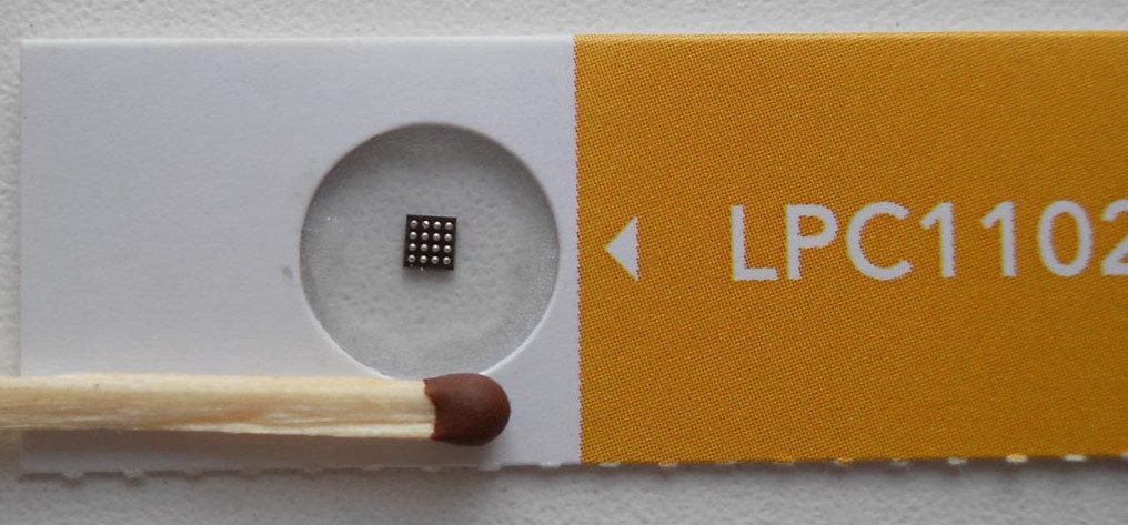
LPC1102 and warm lamp indicator
I was forced to write this text by the article “Freescale reduced the size of the world's smallest microcontroller on ARM architecture” . Three days before the publication of this article, I finished my small project, in which the NXP LPC1102 controller was used - this is a direct competitor described in the article Freescale KL02 and possibly the new KL03. Next will be a comparison of two microcontrollers from NXP (Philips) and Freescale (Motorola), and my project on the LPC1102.
Comparison
At the moment, the documentation on KL03 is not available (only announced), so he will not participate in the comparison, in fact, not much and wanted to, the new KL03 differs little from last year’s KL02. Here are the main differences:
- dimensions are reduced by as much as 0.33mm, for KL02 1.99x1.94mm, for the new KL03 - 1.99 x 1.61mm;
- added 8 kByte ROM in which the factory loader is located.
- reduced the size of the RAM from 4kByte at KL02 to 2kbyte at KL03.
Cuts in two times the most valuable resource - RAM is not the most ingenious idea, but obviously this is the price of adding 8 KB of ROM and reducing the size of the case. After all, the case here, in fact, is the silicon chip itself.
So, we will compare the two closest representatives.
')
<style type="text/css"> .tg {border-collapse:collapse;border-spacing:0;} .tg td{font-family:Arial, sans-serif;font-size:14px;padding:10px 5px;border-style:solid;border-width:1px;overflow:hidden;word-break:normal;} .tg th{font-family:Arial, sans-serif;font-size:14px;font-weight:normal;padding:10px 5px;border-style:solid;border-width:1px;overflow:hidden;word-break:normal;} </style> | LPC1102UK | MKL02Z32CAF4R | |
|---|---|---|
| Dimensions | 2.17 x 2.32 mm | 1.99 x 1.94 mm |
| Lead Pitch | 0.5 mm | 0.4 mm. |
| Number of pins | sixteen | 20 |
| Architecture | ARM Cortex-M0 | ARM Cortex-M0 + |
| Supply voltage | 1.8 - 3.6 V | 1.71-3.6 V |
| Working temperature | -40-85 ° | -40-85 ° |
| Core frequency | 50 MHz | 48MHz |
| PROM | 32K | 32K |
| Ram | 8K | 4K |
| ROM | 16K | - |
| ADC | 10bit | 12bit |
| DAC | - | 6bit |
| SPI | one | one |
| I2C | one | 2 |
| UART | one | one |
| Timers | 2-32bit, 2-16bit | 3-16bit |
| Debugging | SWD | SWD |
The differences by the tenths of a millimeter in the sizes of the cases seem to me quite insignificant, I very much doubt that this may somehow influence the choice between these two processors.
The pitch of conclusions, 0.4 in Motorola versus 0.5 in Philips, in terms of the development of a printed circuit board, the choice is obvious in favor of the latter. Such a small step is an inevitable consequence of the miniaturization of the body. A small step allowed us to add another series of conclusions, with KL02 there are 20, with LPC - 16.
To add “+” to the name of the architecture was undoubtedly worth it, the main and indisputable plus of this plus is extremely low power consumption. In justification of LPC1102, it can be said that it is older than the ARM Cortex M0 + architecture.
Given the difference in architecture, comparing performance, relying on the clock frequency is simply not correct, I find it difficult to say that it is better / higher / faster / more productive. 50 and 48 MHz is very much for those tasks where such miniaturization may be required, in most cases the frequency will be reduced to reduce power consumption. Therefore, the clock frequency will be one of the last criteria when choosing one or another.
32Kb of flash memory “for the program” is more than enough for such a crumb, and your bootloader also fits; there are no questions here. But with the RAM there are questions. NXP tried and
ROM is a permanent storage device, i.e. memory without the possibility of reprogramming. In this memory is the factory (stitched in the manufacture of the chip) boot allows you to flash the user program in a new chip. The firmware is carried out on one of the available interfaces, for example, UART. And this factory loader is only in LPC1102, in KL02 there is simply no such thing. According to the announcement, the factory loader will appear in KL03.
The SPI serial interface is present in both controllers, however, in the controller from NXP this interface is much more functional, which only costs 8 frames of the FIFO buffer (in Freescale - 1 frame) and many more chips that are not in KL02. But there is one significant drawback - the SPI_CLK output is combined with SWD_CLK. This means that it is not possible to debug the SPI operation using the JTAG / SWD adapter. There is a way out; for the debugging period, solder the LPC1104 instead of the LPC1102, where these signals are separated into different terminals.
I2C is unremarkable, but KL02 has two such interfaces, LPC1102 has one. Why I personally don’t understand the two, the bus-type interface, i.e. You can connect multiple devices to one interface, so why two? ... but oh well, let it be, it doesn't seem to interfere.
With timers and their digit capacity, the LPC1102 is richer than that of a competitor. There are 32-bit and more capture / compare outputs. NXP supporters can not but rejoice.
Both controllers have an SWD interface for debugging and programming. Who does not know this two-wire interface, not counting the common wire. Very convenient, unlike JTAG with its multiple signals.
I also want to add the presence of a unique 80-bit identifier in each chip to the piggy bank of the Freescale controller's advantages, sometimes a very useful thing.
As a result, I would say that in my project, all other things being equal, I would choose the Phillips (NXP) controller, stupidly because of 8K of RAM, well, closer it is somehow more familiar or something. Although of course it all depends on the task.
The project on the LPC1102, warm lamp LED.
Hard
Furrowed the Internet, I do not remember in search of what, and then came across such a miracle.

HP Indicator HDSP-2001
A miniature graphical LED display sized to a standard DIP12 package. Gold-plated findings, ceramic case, glass cover (the seller claimed that the sapphire crystal ...) - just a delight, now they do not. The indicator has four familiarity, 7x5 pixels each. The control method is visible from the structural scheme - the shift register 4 * 7bit plus five inputs for enumerating the columns. There is also a shift register output that allows you to easily increase the bit depth.

Block diagram of the HDPS-2001 indicator
Ordered. We arrived. It is urgent to turn on, see how it works. To do this, we take, no, not Arduino, not RasberryPi, not any whale start, which is enough, and not even STM32xxx, and not even AVR, God bless him, but take LPC1102, which has been collecting dust for a long time.
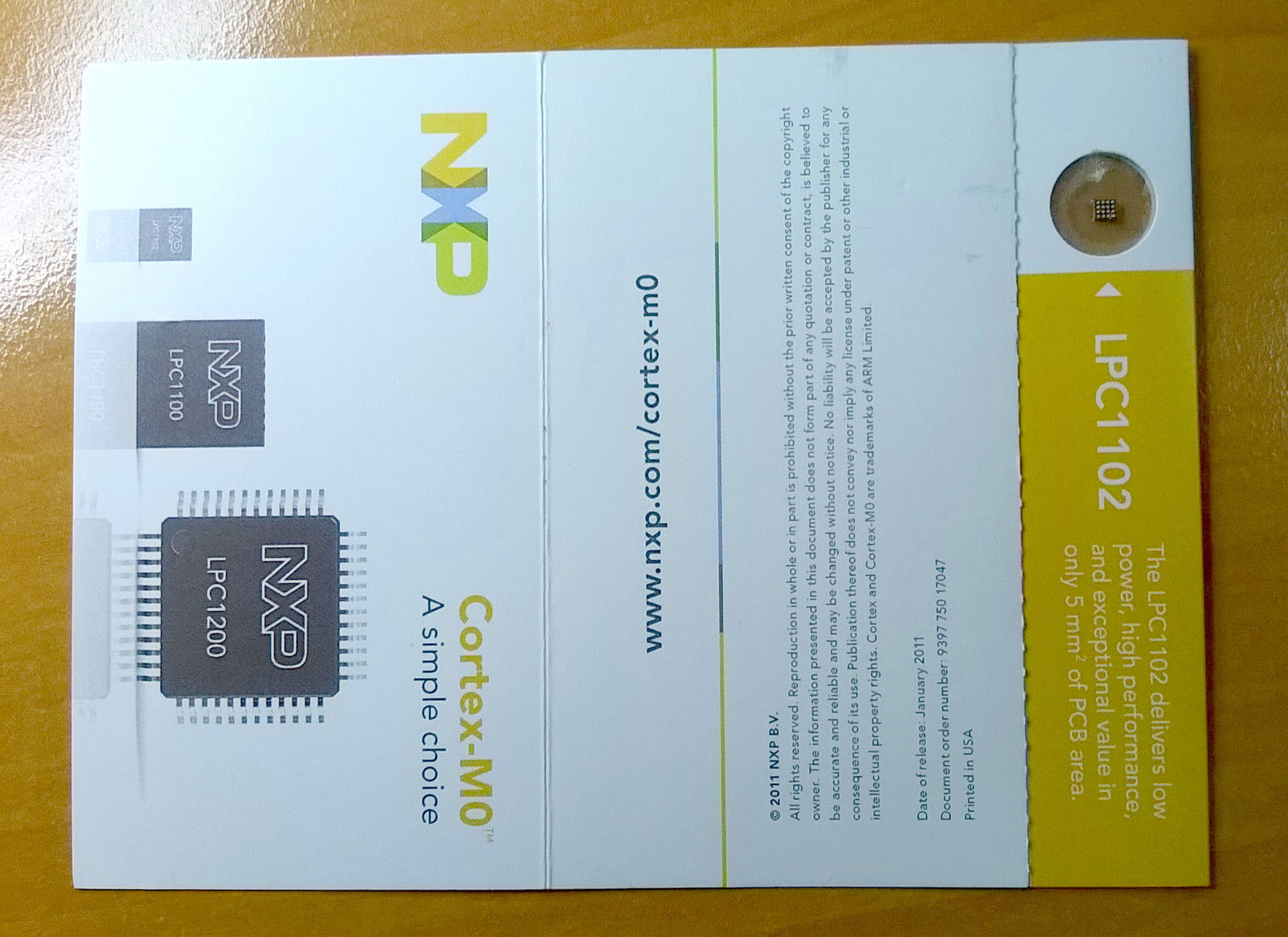
NXP Gift
No, well, and what to
View sweroo

Bottom view

Not yet filled with epoxy resin LPC1102
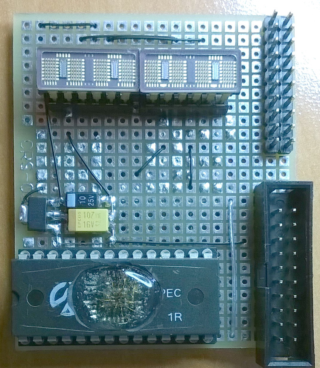
The pictures show the final result when I made this layout, did not plan to write an article - there are no intermediate pictures.
And you can see the following:
- bread board
- standard 20 pin JTAG connector;
- 3.3V linear voltage regulator;
- two HDSP-2001 indicators inserted into the connector.
- LPC1102 microcontroller is decoupled for convenience instead of a crystal in some kind of DIP chip.
- on the reverse side are the keys for igniting the columns.
I am sorry, there is no electrical concept. I wanted to run everything faster. This is fundamentally wrong, a competent engineer should draw a scheme for any trifle, no matter how simple it is. Since Everything is quickly forgotten and in a week it will be very difficult to change something in the circuit design.
Soft
The software was written in C on IAR. Set a goal to make a simple running line. First of all, the “screen buffer” is a two-dimensional array of 8x5 bytes; 8-familiarity, in each familiarity 5 columns, each column 7 bits. Interruption of the system timer 2ms. In the interrupt, turn off the previous column, load the data of the next 8 columns into the shift registers from the “screen buffer” and light them, and so on every 2 ms. The attentive reader remembers that the signals SWD_CLK and SPI_CLK are combined on the same output, therefore the SPI is software, 7-bit. The most difficult is done!
Next, write your putchar which will work with our “screen buffer”, you will need a 5x7 font. The font is not difficult to do yourself, but I took it ready (link below). We write the SetPos function - to indicate in which familiarity to output. Well, the standard printf picks up our redefined putchar. Then every 200 ms to output a line to a new place - the creeping line is ready.
Conclusion
Everything described was done in three evenings, most of the time it took to “cooking” the LPC1102 inside some kind of chip was a topic worthy of a separate post. Having experience, ready and customized tools, sometimes straight arms and most importantly an irresistible desire, this is real. The project has no practical application, just wanted, could, did.
Links
[1] www.nxp.com/products/microcontrollers/cortex_m0_m0/lpc1100/LPC1102UK.html#documentation - LPC1102
[2] www.freescale.com/webapp/sps/site/prod_summary.jsp?code=KL02&fpsp=1&tab=Documentation_Tab - KL02
[3] www.freescale.com/webapp/sps/site/prod_summary.jsp?code=KL03&fpsp=1&tab=Documentation_Tab - KL03
[4] electronix.ru/forum/lofiversion/index.php/t44983.html - Font 5x7, thanks to the user with the nickname “AHTOXA”
[5] www.hparchive.com/PARTS/HP-Displays-HDSP-2010.pdf - Technical documentation for the indicator
Source: https://habr.com/ru/post/218233/
All Articles