Like a car gyro on the steering wheel, measured

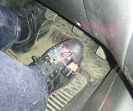
And not only the gyroscope was tied to the steering wheel! The second was on the foot, and the third was pulled by rubber rings to the ashtray cover. All these tricks - in order to find out if the steering wheel does not “lag” and if the gas pedal does not “tupit”.
Although the steering wheel is mechanically connected to the wheels and the accelerator pedal to the throttle, the car does not immediately respond to the driver’s commands. Especially if the gearbox is automatic, and the electronics "tupit." Delays make control much more difficult and can lead to undesirable oscillations. Therefore, it is important to know how fast the car responds to driver commands.
The first way to find delays is to use data from the OBD (On-Board Diagnostics) port. This port is connected to the vehicle's diagnostic bus (CAN bus). That it is used in the service for reading the error codes of the engine and transmission. It also contains information about the current engine speed, fuel consumption, the angle of the gas pedal, the opening of the throttle, etc.
To connect to the car's tire, I bought a typical Chinese “obd reader” for a thousand rubles.
This device can be connected to any modern car. However, a cheap reader does not give more information than on car devices. Those. for our purposes it is useless. On the whole, there are a number of problems with the diagnostic port and bus:
- closed protocols and bus data standards
- unknown accuracy / accuracy of data
- unpredictable delays
- I do not understand anything
- Therefore, it was decided to assemble their own measuring instruments from improvised gyroscopes and arduins.
')
Measurement Technique
The first gyroscope was “securely” tied to the steering wheel with masking tape. He determined the steering angle. The second gyro is pulled to the driver's leg with hair ties. He passed on the brake / gas pedal. The last device was fixed in the cabin. In addition to the gyroscope, he had an accelerometer and collected data from other sensors. Then the data was sent to the laptop via a virtual COM port via usb.
As the captain suggests, in order to measure delays, it is necessary to synchronize the time on all sensors. Now synchronization is released “vlob”: the receiving sensor subtracts the magic constant from the time of signal arrival (determined by interruption from the wireless module) - the time required to send and receive data.

To determine this magic constant Zhetsko pressed the sensors to each other and rotated. The delay between the readings gives just that “magic constant”.
About sensors
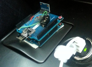
Two modules based on Arduino Uno were assembled:
- Additional scheme (shild) for prototyping, mounted on top of arduin;
- gyro based on MPU-6050, soldered to shield;
- radio module nrf24l01 +, soldered to the shield.
One model based on arduino micro:
- double-sided board for laser-iron technology;
- logic level matching board 5v <-> 3.3v;
- MPU-6050 based gyroscope on I2C interface;
- radio nrf24l01 +.
Measurements
I don’t have a car, so we tested it on a Mitsubishi Lancer of my friend, Konstantin.
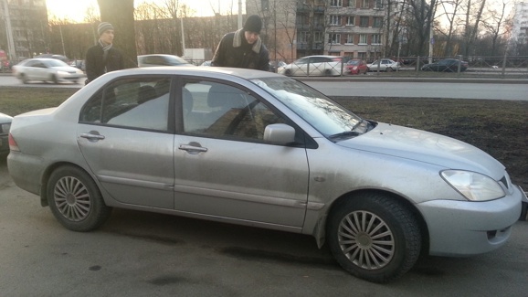
All tests were conducted on a dead end section of a public road, so the speeds are not great.
Kostya was driving at a speed of about 30 km / h, actively turning the steering wheel and modulating the gas pedal. Nearby training cars jumped to the sides, observing our inadequate actions of a used Lancer.
At that time I was sitting with a laptop in the passenger seat and was managing to receive data from the sensors.
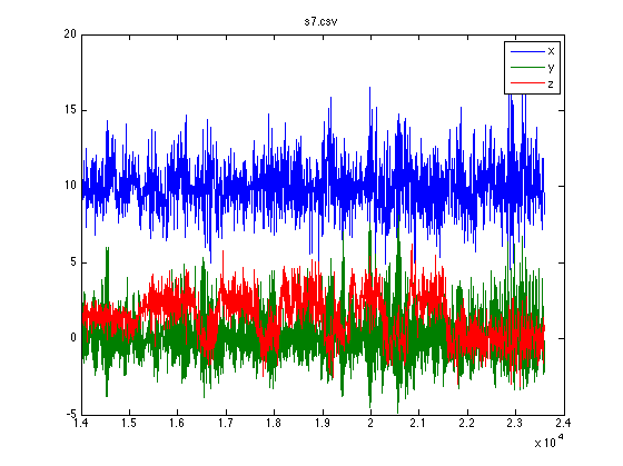
The following graph shows typical readings of a gyroscope attracted to the leg:
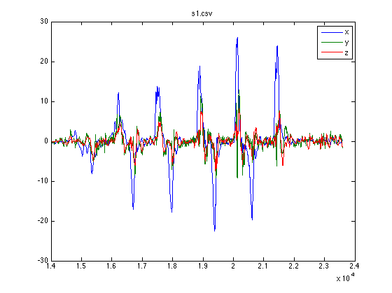
Vibrations from the engine, the hands of the driver, the road - everything leads to noise. Especially clearly they appear on the charts of the acceleration of the car body.
To combat high-frequency noises, the data was pre-processed by a low-pass filter (filterfilt matlab). The filter was chosen so as not to introduce an additional delay into the signal.
I note that the gyroscopes determine the speed of rotation of the gas pedal and the steering wheel, and we need an angle. For this, the readings from the sensors on the steering wheel and the foot have been integrated. Then, to calculate the delays, cross-correlation was used (the finddelay function of the matlab).
The graph below shows the angle of rotation of the pedal (foot), the acceleration of the vehicle along the corresponding axis and the acceleration of the vehicle, corrected for the calculated delay:

Kostya pressed and released the gas pedal, and the car reacted only after 124 milliseconds. The speed is about 30 km / h, the speed is 3000 rpm.
At a speed of 30km / h, the delay of the car on steering turns, according to the results of individual tests, ranged from 90 to 95ms.

Plans
- Measure delays on other cars;
- Measure the time from the moment you press the gas pedal (or release the clutch) to 100 km / h (or 402 m).
- Measure the reaction force on the steering wheel in turn (feedback);
- Measure the driver's pulse before / during / after passing the track.
Source: https://habr.com/ru/post/218029/
All Articles