Purpose of gyroscopic sensors and their use in modern navigation systems
The efficiency and competitiveness of modern aircraft (LA) is largely determined by the perfection of the gyroscopic sensors of primary information, on the basis of which the navigation systems and control systems of the aircraft are built.
Currently, there is a large variety of different types of gyro sensors, the correct use of which provides the necessary performance of the aircraft.
Each type of gyroscopic sensors can find the optimal niche application. When choosing a gyroscopic sensor, its following characteristics are taken into account: accuracy, reliability of operation, power consumption, overall dimensions and cost. Depending on the requirements for control systems and navigation systems, the appropriate type of gyro sensor is selected.
Nevertheless, from the whole variety of sensors it is possible to distinguish the most promising according to the above characteristics. These are laser gyroscopes (LH), fiber optic (VOG), wave solid-state (VHG), and micromechanical gyroscopes (MMG).
Their main advantage is increased reliability of work due to the lack of rapidly rotating rotors and cardanals, minimal power consumption due to the implementation of the main functional units based on service microelectronics and the possibility of increasing the accuracy characteristics by mathematical processing of the primary sensor signals in microprocessors.
Gyroscopic sensors are sources of primary information in the construction of flight and navigation systems of aircraft.
In flight systems, they are used mainly as sensors of angular velocity in the feedback circuits of automatic control systems. In navigation systems, as sensors for the aircraft’s angular position or an indicator of the zero position of the gyro-stabilized platform. Accelerometers are used as linear acceleration sensors.
Consider some schemes for constructing inertial navigation systems based on gyroscopic sensors. The main objectives of any navigation system is to determine the location of the aircraft in geographic coordinates - longitude (λ) and latitude (φ) location, speed (υ) and height (h) of flight, angular position relative to its center of gravity in inertial space - course () , pitch (ϑ), roll (γ). Fig.1.1 and Fig.1.2 show these parameters adopted in aviation.

Fig. 1.1 orientation angles of the aircraft
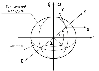
Fig.1.2 Coordinate systems in which the position of the aircraft is determined
In Figures 1.1, 1.2: - geographic coordinate system, where the axis ξ coincides with the axis of rotation of the Earth and is directed to the North; axis ς - lies in the equatorial plane and passes through the Greenwich meridian; axis η - also lies in the plane of the equator and is directed to the East.
  - the basic accompanying trihedron, relative to which the angular position of the aircraft is determined, where the X axis is directed to the East; Y axis - directed to the north along the meridian; Z axis - vertical terrain.
  - axes of the measuring trihedron of the inertial navigation system.
Inertial navigation systems are divided into two large groups - platform and freestanding.
Regardless of the type of navigation system, information about the speed of flight of the aircraft and the distance traveled is obtained from the readings of accelerometers by integrating their output signals — linear accelerations . However, the accuracy of this information depends on the accuracy of determining the position of the axes of sensitivity of accelerometers relative to the basic measuring axes defined in the inertial space - the axes of the inertial accompanying trihedron.
In platform navigation systems, the specified position of the axes of the basic accompanying trihedron is achieved by stabilizing the position in the inertial space of the platform on which accelerometers are installed. The required stability of the position is ensured by the automatic control systems of the three frames of the Cardan suspension, in which two or three-stage gyroscopes with a rapidly rotating rotor are used as sensors of the control system, and the moment sensors (DM) of the corresponding cardan frames are used as the actuator.
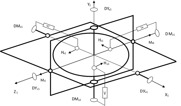
Fig.1.3 Scheme of building a platform navigation system
Gyroscopes are installed on the same platform as the accelerometers (Figure 1.3). The higher the accuracy of the gyroscopes, the less accurate the stabilization of the position of the platform, the more accurately the speed and position of the aircraft are determined.
Information about the angular position of the center of gravity of the aircraft is removed from the three angle sensors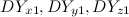 installed along the axes of the frames of the cardan suspension.
As an example, consider stabilizing the position of the platform along one of the measuring axes of the navigation system - along the axis (Fig. 1.3). When the platform rotates under the influence of the disturbing moment
  around the axis gyro axis
  will begin to precess (rotate) around the axis
  at angle ε. In the sensor of the angle of the gyroscope appears the error voltage Uε, which after amplification is fed to the torque motor
  pitch frame. Last will create moment
  , under the action of which the frame will return to its original position. In this case, the gyro rotor will begin to precess in the opposite direction until Uε becomes zero. Information about the angle of rotation of the aircraft around the pitch axis will be obtained from the angle sensor
  mounted on the axis of the frame. Similarly, control and determination of the heading angle and roll along the other two axes of the cardan suspension are carried out.
')
From the presented scheme, the main drawbacks of the platform inertial systems are visible - a large number of mechanical rotating elements, the presence of analogue control systems and, as a result, the low reliability of the system.
The emergence and development of gyroscopic sensors based on new physical principles - LH, VOG, VTG, MMG, in which there are no fast rotating mechanical rotors, allowed to proceed to the creation of inertial navigation systems of increased reliability - strapdown inertial navigation systems (SINS).
There is no cardan suspension in the BINS, and the basic accompanying trihedron plays the role of a stabilized platform. (Fig. 1.2), relative to which is determined by the position of the measuring axis of the SINS during the flight of the aircraft.
Three single-axis gyros and three accelerometers are used as gyroscopic sensors in a SINS, which are rigidly mounted in a block of sensitive SINS elements along three orthogonal measuring axes (Fig. 1.4). The block of sensitive elements, in turn, is rigidly connected with the body of the aircraft.
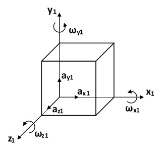
Fig. 1.4. Measuring axes of the block of sensitive elements BINS
Gyros are used to determine the angular position of the measuring axes of the block of sensitive elements relative to the basic accompanying trihedron, that is, the angles of pitch, pitch, and course of the aircraft. Since the gyroscopes used in the SINS work, as a rule, in the mode of angular velocity sensors, their readings are integrated to determine the indicated angles . Accelerometer readings, as in platform systems, are used to determine the speed of movement of the aircraft and the path traveled by it. Accelerometer readings are also integrated for this purpose.
  .
.
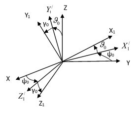
Fig.1.5 Initial angles of the SINS exhibition
Before the flight begins, the BINS exhibition is performed, that is, the determination of the initial angular position measuring axes ( ) relative to the axes of the basic accompanying trihedron ( ) (Fig. 1.5). The magnitude of these angles is entered into the on-board computer and taken into account when determining the angular position of the aircraft during its flight.
The complete absence of mechanical rotating parts makes the SINS an extremely reliable system in operation, and the use of a high-speed on-board computer makes it possible to increase the accuracy of such a system due to the algorithmic compensation of the errors of gyroscopic sensors caused by fluctuations in ambient temperature and mechanical effects.
But regardless of the type of navigation system, its technical capabilities are determined primarily by the technical characteristics of gyroscopic sensors.
In this post, a small part of the material presented in the book of Ph.D. Galkina V.I. "Perspective aircraft gyros" ISNB 978-3-659-47948-9
In the future I will provide some more information from this book. But for those who are interested and to whom the article was useful, I ask you to express interest in buying a book.
Currently, there is a large variety of different types of gyro sensors, the correct use of which provides the necessary performance of the aircraft.
Each type of gyroscopic sensors can find the optimal niche application. When choosing a gyroscopic sensor, its following characteristics are taken into account: accuracy, reliability of operation, power consumption, overall dimensions and cost. Depending on the requirements for control systems and navigation systems, the appropriate type of gyro sensor is selected.
Nevertheless, from the whole variety of sensors it is possible to distinguish the most promising according to the above characteristics. These are laser gyroscopes (LH), fiber optic (VOG), wave solid-state (VHG), and micromechanical gyroscopes (MMG).
Their main advantage is increased reliability of work due to the lack of rapidly rotating rotors and cardanals, minimal power consumption due to the implementation of the main functional units based on service microelectronics and the possibility of increasing the accuracy characteristics by mathematical processing of the primary sensor signals in microprocessors.
Gyroscopic sensors are sources of primary information in the construction of flight and navigation systems of aircraft.
In flight systems, they are used mainly as sensors of angular velocity in the feedback circuits of automatic control systems. In navigation systems, as sensors for the aircraft’s angular position or an indicator of the zero position of the gyro-stabilized platform. Accelerometers are used as linear acceleration sensors.
Consider some schemes for constructing inertial navigation systems based on gyroscopic sensors. The main objectives of any navigation system is to determine the location of the aircraft in geographic coordinates - longitude (λ) and latitude (φ) location, speed (υ) and height (h) of flight, angular position relative to its center of gravity in inertial space - course () , pitch (ϑ), roll (γ). Fig.1.1 and Fig.1.2 show these parameters adopted in aviation.
Fig. 1.1 orientation angles of the aircraft
Fig.1.2 Coordinate systems in which the position of the aircraft is determined
In Figures 1.1, 1.2:
- geographic coordinate system, where the axis ξ coincides with the axis of rotation of the Earth and is directed to the North; axis ς - lies in the equatorial plane and passes through the Greenwich meridian; axis η - also lies in the plane of the equator and is directed to the East. - the basic accompanying trihedron, relative to which the angular position of the aircraft is determined, where the X axis is directed to the East; Y axis - directed to the north along the meridian; Z axis - vertical terrain. - axes of the measuring trihedron of the inertial navigation system.Inertial navigation systems are divided into two large groups - platform and freestanding.
Regardless of the type of navigation system, information about the speed of flight of the aircraft and the distance traveled is obtained from the readings of accelerometers by integrating their output signals — linear accelerations
. However, the accuracy of this information depends on the accuracy of determining the position of the axes of sensitivity of accelerometers relative to the basic measuring axes defined in the inertial space - the axes of the inertial accompanying trihedron.In platform navigation systems, the specified position of the axes of the basic accompanying trihedron is achieved by stabilizing the position in the inertial space of the platform on which accelerometers are installed. The required stability of the position is ensured by the automatic control systems of the three frames of the Cardan suspension, in which two or three-stage gyroscopes with a rapidly rotating rotor are used as sensors of the control system, and the moment sensors (DM) of the corresponding cardan frames are used as the actuator.
Fig.1.3 Scheme of building a platform navigation system
Gyroscopes are installed on the same platform as the accelerometers (Figure 1.3). The higher the accuracy of the gyroscopes, the less accurate the stabilization of the position of the platform, the more accurately the speed and position of the aircraft are determined.
Information about the angular position of the center of gravity of the aircraft is removed from the three angle sensors
installed along the axes of the frames of the cardan suspension.As an example, consider stabilizing the position of the platform along one of the measuring axes of the navigation system - along the axis
(Fig. 1.3). When the platform rotates under the influence of the disturbing moment around the axis gyro axis will begin to precess (rotate) around the axis at angle ε. In the sensor of the angle of the gyroscope appears the error voltage Uε, which after amplification is fed to the torque motor pitch frame. Last will create moment , under the action of which the frame will return to its original position. In this case, the gyro rotor will begin to precess in the opposite direction until Uε becomes zero. Information about the angle of rotation of the aircraft around the pitch axis will be obtained from the angle sensor mounted on the axis of the frame. Similarly, control and determination of the heading angle and roll along the other two axes of the cardan suspension are carried out.')
From the presented scheme, the main drawbacks of the platform inertial systems are visible - a large number of mechanical rotating elements, the presence of analogue control systems and, as a result, the low reliability of the system.
The emergence and development of gyroscopic sensors based on new physical principles - LH, VOG, VTG, MMG, in which there are no fast rotating mechanical rotors, allowed to proceed to the creation of inertial navigation systems of increased reliability - strapdown inertial navigation systems (SINS).
There is no cardan suspension in the BINS, and the basic accompanying trihedron plays the role of a stabilized platform.
(Fig. 1.2), relative to which is determined by the position of the measuring axis of the SINS during the flight of the aircraft.Three single-axis gyros and three accelerometers are used as gyroscopic sensors in a SINS, which are rigidly mounted in a block of sensitive SINS elements along three orthogonal measuring axes (Fig. 1.4). The block of sensitive elements, in turn, is rigidly connected with the body of the aircraft.
Fig. 1.4. Measuring axes of the block of sensitive elements BINS
Gyros are used to determine the angular position of the measuring axes of the block of sensitive elements relative to the basic accompanying trihedron, that is, the angles of pitch, pitch, and course of the aircraft. Since the gyroscopes used in the SINS work, as a rule, in the mode of angular velocity sensors, their readings are integrated to determine the indicated angles
. Accelerometer readings, as in platform systems, are used to determine the speed of movement of the aircraft and the path traveled by it. Accelerometer readings are also integrated for this purpose. .Fig.1.5 Initial angles of the SINS exhibition
Before the flight begins, the BINS exhibition is performed, that is, the determination of the initial angular position
measuring axes ( ) relative to the axes of the basic accompanying trihedron ( ) (Fig. 1.5). The magnitude of these angles is entered into the on-board computer and taken into account when determining the angular position of the aircraft during its flight.The complete absence of mechanical rotating parts makes the SINS an extremely reliable system in operation, and the use of a high-speed on-board computer makes it possible to increase the accuracy of such a system due to the algorithmic compensation of the errors of gyroscopic sensors caused by fluctuations in ambient temperature and mechanical effects.
But regardless of the type of navigation system, its technical capabilities are determined primarily by the technical characteristics of gyroscopic sensors.
In this post, a small part of the material presented in the book of Ph.D. Galkina V.I. "Perspective aircraft gyros" ISNB 978-3-659-47948-9
In the future I will provide some more information from this book. But for those who are interested and to whom the article was useful, I ask you to express interest in buying a book.
Source: https://habr.com/ru/post/218027/
All Articles