Networks for the smallest. Part nine. Multicast
All issues
8.1. Networks for the smallest. Micro Issue number 3. iBGP
8. Networks for the smallest. Part Eight BGP and IP SLA
7. Networks for the smallest. Part Seven. VPN
6. Networks for the smallest. Part six. Dynamic routing
5. Networks for the smallest: Part Five. NAT and ACL
4. Networks for the smallest: Part Four. STP
3. Networks for the smallest: Part Three. Static routing
2. Networks for the smallest. Part two. Switching
1. Networks for the smallest. Part one. Connection to the equipment cisco
0. Networks for the smallest. Part zero. Planning
Our speculative provider linkmeup matures and grows over quietly with all the services of ordinary telecom operators. Now we have grown to IPTV.
This implies the need to configure multicast routing and first of all an understanding of what multicast is all about.
This is the first deviation from the familiar IP-network principles. Still, the multicast paradigm is fundamentally different from the warm tube unicast.
It may even be said that this somewhat challenges the flexibility of your mind in understanding new approaches.
This article will focus on the following:
- General understanding of Multicast
- IGMP protocol
- PIM protocol
- >>> PIM Dense Mode
- >>> Pim Sparse Mode
- >>> SPT Switchover - RPT-SPT Switching
- >>> DR, Assert, Forwarder
- >>> Automatic RP selection
- >>> SSM
- >>> BIDIR PIM
- Multicast channel level
- >>> IGMP-Snooping
- >>> MVR

')
Traditional video tutorial:
At the dawn of my development as an engineer, the topic of multicast scared me incredibly, and I connect this with the psychotrauma of my first experience with him.
“ So, Marat, urgently, you need to forward the video stream to our new building in the city center before noon - the provider will give it to us here on the second floor ” - I heard one wonderful morning. All that I knew about multicaste then is that the sender is one, there are many recipients, and, it seems, the IGMP protocol is somehow involved there.
As a result, before noon we tried to run the whole thing - I forwarding the most ordinary VLAN from the entry point to the exit point. But the signal was unstable - the picture froze, collapsed, interrupted. I was in a panic trying to figure out what could be done with IGMP at all, tinked, tacked, turned on multicast routing, IGMP-snooping, checked the delay and loss a thousand times - nothing helped. And then suddenly it all worked. Of course, stable, trouble-free.
This gave me a vaccination against multicast, and for a long time I did not show any interest in it.
Much later, I came to the following rule:
And now I understand from the height of the crashed cases that there could not have been any problems with setting up the network part - the final equipment was buggy.

Keep calm and trust me. After this article, such things will not frighten you.
General understanding of Multicast
As you know, there are the following types of traffic:
Unicast - unicast - one sender, one recipient. ( Example: HTTP page request from the WEB server ).
Broadcast — broadcast — one sender, recipients — all devices in the broadcast segment. ( Example: ARP request ).
Multicast - multicast - one sender, many recipients. ( Example: IPTV ).
Anycast - unicast to the nearest host - one sender, there are many recipients in general, but in fact the data is sent only to one. ( Example: Anycast DNS ).
Since we decided to talk about multicaste, then perhaps we will begin this paragraph with the question of where and how it is used.
The first thing that comes to mind is television (IPTV) - one source server sends traffic that many clients want to receive at once. This defines the term itself - multicast - multicast. That is, if Broadcast already known to you means broadcasting to everyone, multicast means broadcasting to a specific group.
The second application is, for example, replication of the operating system on many computers at once. This means downloading large amounts of data from a single server.
Possible scenarios: audio and video conferencing (one says - everyone is listening), e-commerce, auctions, exchanges. But this is in theory, but in practice rarely there is still used multicast.
Another use is for protocol service messages. For example, OSPF in its broadcast domain sends its messages to the addresses 224.0.0.5 and 224.0.0.6. And they will be processed only by those nodes on which OSPF is running.
We formulate two basic principles of multicast distribution:
- The sender sends only one copy of traffic, regardless of the number of recipients.
- Traffic is received only by those who are really interested in it.
In this article for practice, we will take IPTV, as the most obvious example.
Example I
Let's start with the simplest case:
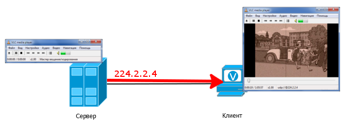
The source server is configured to broadcast to the group 224.2.2.4 - this means that the server sends traffic to the IP address 224.2.2.4. On the client, the video player is configured to accept a stream of group 224.2.2.4.
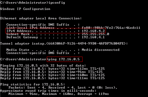
At the same time, note that the client and the server do not have to have addresses from the same subnet and ping each other - it is enough that they are in the same broadcast domain.
The multicast stream just flows from the server, and the client simply accepts it. You can try it right in your workplace by connecting two computers with a patchcord and running, for example, VLC.
It should be noted that in the multicast there is no alarm from the source, they say, "Hello, I am the Source, do not need a little multicast?" .
The source server simply starts broadcasting multicast packets to its interface. In our example, they go directly to the client and he, in fact, immediately takes them.
If you catch packets on this link, you will see that multicast traffic is nothing but a sea of UDP packets.

Multicast is not tied to any particular protocol. In fact, everything that defines it is addresses. However, if we talk about its application, then in the absolute majority of cases it is used exactly UDP. This is easily explained by the fact that usually via multicast data is transmitted that is needed here and now. For example, video. If a piece of the frame is lost, and the sender will try to send it again, as it happens in TCP, then most likely this piece will be late, and where to show it then? The train left. Exactly the same with sound.
Accordingly, it is not necessary to establish a connection, so TCP is useless here.
What is so strikingly different from the unicast multicast? I think you already have a guess. And you are probably right.
Normally, we have 1 recipient and 1 sender - each of them has one unique IP address. The sender knows exactly where to send the packet and puts this address in the IP header. Each intermediate node, due to its routing table, knows exactly where to forward the packet. Unicast traffic between two nodes passes freely through the network. But the problem is that in the normal package, only one IP address of the recipient is indicated.
What if the same traffic has multiple recipients? In principle, it is possible to extend the unicast approach and, in such a situation, send a copy of the packet to each client. Customers will not notice the difference - even though it is one, even though there are a thousand of them, but the difference will be clearly visible on your data transmission channels.

Suppose we are transmitting one SD channel from a multicast server. Let him use 2 MB / s. There are 30 such channels in total, and each channel is watched by 20 people at a time. Total is 2 MB / s * 30 channels * 20 people = 1200 MB / s or 1.2 Gb / s only on TV in the case of unicast. But there are still HD channels, where you can safely multiply this figure by 2. And where is the place for torrents?
That is why the block of class D addresses was embedded in IPv4 : 224.0.0.0/4 (224.0.0.0394.255.255.255). Addresses in this range define a multicast group. One address is one group, usually it is denoted by the letter " G ".
That is, saying that the client is connected to the group 224.2.2.4, we mean that it receives multicast traffic with the destination address 224.2.2.4.
Example II
Add a switch to the scheme and a few more clients:
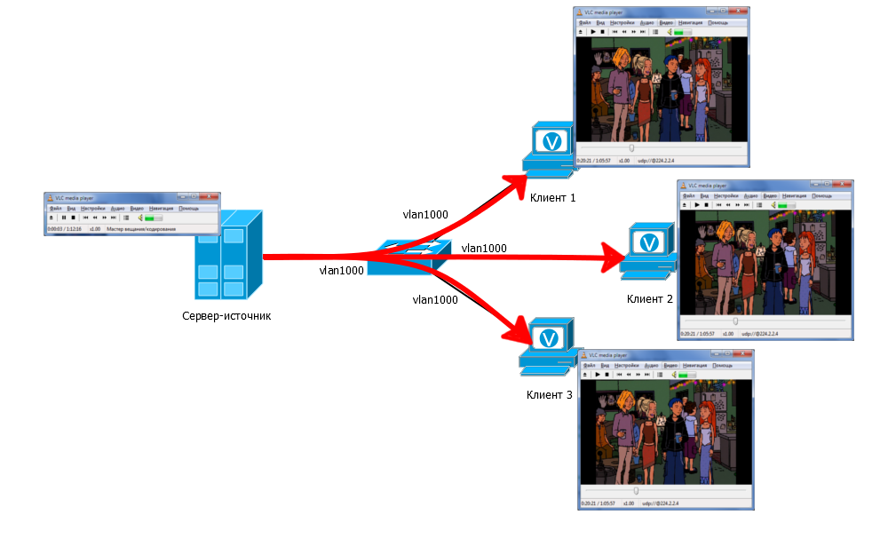
The multicast server still broadcasts to the group 224.2.2.4. On the switch, all 4 ports must be in the same VLAN. Traffic arrives at the switch and by default is sent to all ports of a single VLAN. So all customers receive this traffic. They have the same group address of 224.2.2.4 on everyone in the video player.
Actually, all these devices become members of this multicast group. Membership in it is dynamic: anyone, at any time, can enter and exit from it.
In this situation, traffic will be received even by those who, in general, did not want this, that is, neither the player nor anything else is running on it. But only if it is in the same VLAN. Later we will figure out how to deal with it.
Note that in this case, only one copy of traffic per switch arrives from the source server, and not a separate copy per client. And in our example with SD channels, the port loading between the source and the switch will not be 1.2 Gb / s, but only 60 Mb / s (2 Mb / s * 30 channels).
As a matter of fact, this whole huge range (224.0.0.0-239.255.255.255) can be used.
Well, almost all of them - the first addresses (range 224.0.0.0/23) are reserved for known protocols.
List of reserved IP addresses
| Address | Value |
|---|---|
| 224.0.0.0 | Not used |
| 224.0.0.1 | All nodes in this segment |
| 224.0.0.2 | All multicast nodes of this segment |
| 224.0.0.4 | This address was reserved for the late DVMRP protocol. |
| 224.0.0.5 | All OSPF Segment Routers |
| 224.0.0.6 | All DR Router Segments |
| 224.0.0.9 | All RIPv2 Segment Routers |
| 224.0.0.10 | All EIGRP Segment Routers |
| 224.0.0.13 | All PIM Segment Routers |
| 224.0.0.18 | All VRRP Segment Routers |
| 224.0.0.19-21 | All IS-IS segment routers |
| 224.0.0.22 | All IGMP Segment Routers (v2 and v3) |
| 224.0.0.102 | All HSRPv2 / GLBP Segment Routers |
| 224.0.0.107 | PTPv2 - Precision Time Protocol |
| 224.0.0.251 | mDNS |
| 224.0.0.252 | Llmnr |
| 224.0.0.253 | Teredo |
| 224.0.1.1 | NTP |
| 224.0.1.39 | Cisco Auto-RP-Announce |
| 224.0.1.40 | Cisco Auto-RP-Discovery |
| 224.0.1.41 | H.323 Gatekeeper |
| 224.0.1.129-132 | PTPv1 / PTPv2 |
| 239.255.255.250 | SSDP |
The range of 224.0.0.0/24 is reserved for link-local communication. Multicast packets with such destination addresses cannot exceed the limits of one broadcast segment.
The range of 224.0.1.0/24 is reserved for protocols that need to transmit a multicast across the entire network, that is, pass through routers.
Here, in fact, the most basic things about multicast.
We have considered a simple situation where the source and the receiver are in the same network segment. The traffic received by the switch is simply sent to all ports by it - no magic.
But for the time being it is not at all clear how the traffic from the server reaches the clients, when there is a huge provider network linkmyap between them? Yes, and from where, in fact, will be known who the client? We cannot manually register routes, simply because we do not know where customers may be. Ordinary routing protocols will not answer this question. So we come to the understanding that multicast delivery is something completely new to us.
In general, in order to deliver a multicast from a source to a recipient, there are currently many protocols - IGMP / MLD, PIM, MSDP, MBGP, MOSPF, DVMRP.
We will focus on two of them that are currently in use: PIM and IGMP.
With the help of IGMP, the final recipient clients inform the closest routers that they want to receive traffic. A PIM builds the path of movement of multicast traffic from the source to the recipients via routers.

Igmp
Let's go back to the dump. Do you see this top package, after which the multicast stream flowed?

This is the IGMP message that the client sent when we clicked on Play. That is how he reports that he wants to receive traffic for the group 224.2.2.4.
IGMP - Internet Group Management Protocol is a network protocol for the interaction of clients of multicast traffic and the closest router to them.
IPv6 uses MLD (Multicast Listener Discovery) instead of IGMP. The principle of their work is absolutely the same, so you can easily change IGMP to MLD, and IP to IPv6 from here on.
How exactly does IGMP work?
Perhaps you need to start with the fact that the protocol has three versions: IGMPv1, IGMPv2, IGMPv3. The most used one is the second one, the first one is almost forgotten, therefore we will not talk about it, the third one is very similar to the second one.
Focusing on the second, as the most revealing one, and consider all the events from the client’s connection to the group and its exit from it.
The client will also request the group 224.2.2.4 through the VLC player.
The role of IGMP is very simple: if there are no clients, you do not need to send multicast traffic to the segment. If a client appears, it notifies the routers via IGMP that it wants to receive traffic.
In order to understand how everything happens, take the following network:

Suppose that the router is already configured to receive and process multicast traffic.

1. As soon as we started the application on the client and set the group 224.2.2.4, the IGMP Membership Report packet will be sent to the network — the node “reports” that it wants to receive traffic from this group.

In IGMPv2 Report, it is sent to the address of the desired group, and in parallel it is also indicated in the packet itself. These messages should live only within their segment and not be sent anywhere by routers, so they have a TTL 1.
Often in the literature you can find mention of IGMP Join . Do not worry - this is an alternative name for the IGMP Membership Report.
2. The router receives IGMP-Report and, realizing that there are now clients behind this interface, it enters the information in its tables

This is information output by IGMP. The first group is requested by the client. The third and fourth are the service groups of the SSDP protocol built into Windows. The second is a special group that is always present on Cisco routers — it is used for the Auto-RP protocol, which is activated by default on routers.
The FE0 / 0 interface becomes downstream for group 224.2.2.4 traffic — it will need to send the received traffic to it.
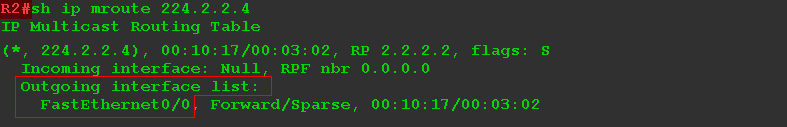
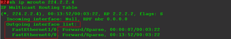
Along with the usual unicast routing table, there is also a multicast:

The presence of clients is indicated by the first record (*, 224.2.2.4) . And the entry (172.16.0.5, 224.2.2.4) means that the router knows about the source of the multicast stream for this group.
It can be seen from the output that traffic for group 224.2.2.4 comes through FE0 / 1, and it must be transmitted to port FE0 / 0.
The interfaces to which traffic is to be transferred are included in the list of downstream interfaces - OIL - Outbound Interface List .
We will analyze the show ip mroute command in more detail later.
Above on the dump you see that as soon as the client sent the IGMP-Report, immediately after it flew UDP - this is a video stream.
3. The client began to receive traffic. Now the router must sometimes check that it still has recipients so that it does not want to broadcast for nothing if suddenly there are no clients left. To do this, it periodically sends an IGMP Query request to all its downstream interfaces.
* Dump filtered by IGMP * .

By default, this happens every 60 seconds. TTL of such packets is also 1. They are sent to the address 224.0.0.1 - all nodes in this segment - without specifying a specific group. Such Query messages are called General Query - common. Thus, the router asks: “Guys, and who else wants to receive what?”.
Having received IGMP General Query, any host that listens to any group must send an IGMP Report, as it did when connecting. In Report, of course, should be the address of the group of interest.
* Dump filtered by IGMP * .

If, in response to Query, there is at least one Report for the group on the router, then there are more clients, it continues to broadcast to the interface from which this Report came, the traffic of this group itself.
If for 3 consecutive Query there was no response for some group from the interface, the router deletes this interface from its multicast routing table for this group - it stops sending traffic there.
On his own initiative, the client usually sends Report only when connected, then it simply responds to Query from the router.
An interesting detail in the client's behavior: having received the Query, he is not in a hurry to immediately reply to Report. The node takes a timeout length from 0 to Max Response Time , which is specified in the incoming Query:
When debugging or in the dump, by the way, you can see that it can take several seconds between receiving a different Report.
This was done so that hundreds of clients all in a crowd did not flood the network with their Report packages, having received General Query. Moreover, only one client usually sends Report.
The fact is that Report is sent to the address of the group, and therefore comes to all customers. Having received Report from another client for the same group, the node will not send its own. The logic is simple: the router has already received this very Report and knows that there are customers, it does not need more.
This mechanism is called Report Suppression .
Further in the article we will talk about why this mechanism actually very rarely works .

4. This continues for centuries, until the client wants to leave the group (for example, turn off the player / TV). In this case, it sends IGMP Leave to the group address.

The router receives it and in theory should disconnect. But after all, he cannot disable one specific client — the router does not distinguish between them — it simply has a downlink interface. And behind the interface there can be several clients. That is, if the router removes this interface from its OIL (Outgoing Interface List) list for this group, the video will turn off at all.
But it is also impossible not to delete it completely - all of a sudden it was the last client - why then should it be wasted?
If you look into the dump, you will see that after receiving the Leave, the router continues to send the stream for some time. The fact is that the router, in response to Leave, sends IGMP Query to the address of the group for which this Leave came to the interface from which it came. This package is called Group Specific Query . Only those clients that are connected to this particular group respond to it.

If the router received a response Report for the group, it continues to broadcast to the interface, if not received, it deletes after the timer expires.
In total, after receiving the Leave, two Group Specific Query are sent - one mandatory, the second control.
* Dump filtered by IGMP * .

Next, the router stops the flow.
Querier
Consider a slightly more complicated case:

Two (or more) routers that can broadcast traffic are connected to the client segment. If nothing is done, multicast traffic will be duplicated - both routers will receive a Report from the clients. To avoid this, there is a mechanism for choosing Querier - the poller. The one who wins will send Query, monitor the Report and respond to Leave, and, accordingly, it will send traffic to the segment. The loser will only listen to the Report and keep a finger on the pulse.
Elections are fairly simple and intuitive.
Consider the situation since the inclusion of routers R1 and R2.
1) Activated IGMP on the interfaces.
2)At first, by default, each of them considers itself Querier.
3) Everyone sends IGMP General Query to the network. The main goal is to find out if there are any clients, and in parallel - to announce to other routers in the segment, if any, about their desire to participate in the elections.
4) General Query is received by all devices in the segment, including other IGMP routers.
5) Having received such a message from a neighbor, each router evaluates who is more worthy.
6) A router with a smaller IP wins (indicated in the Source IP field of the IGMP Query package). He becomes Querier, all others - Non-Querier.
7)Non-Querier starts a timer that resets each time a Query with a lower IP address arrives. If, before the timer expires (more than 100 seconds: 105-107), the router does not receive a Query with a lower address, it declares itself to Querier and assumes all relevant functions.
8) If Querier gets Query with a smaller address, it disclaims these responsibilities. Querier becomes a different router with less IP.
That rare case, when measured, who has less.
The Querier election is a very important multicast procedure, but some insidious non-RFC vendors can put a sturdy stick in their wheels. I am now talking about IGMP Query with source address 0.0.0.0, which can be generated by the switch. Such messages should not be involved in choosing Querier, but be prepared for anything. Here is an example of a very complex long-playing problem.
A couple more words about other versions of IGMP
Version 1 differs in essence only in that there is no Leave message in it . If the client does not want to receive more traffic from this group, he simply stops sending Report in response to Query. When there is not a single client, the router will time out to send traffic.
In addition, Querier selections are not supported . To avoid duplication of traffic, a higher protocol is responsible, for example, PIM, which we will discuss below .
Version 3 supports everything that IGMPv2 supports, but there are a number of changes. First, the Report is sent not to the group address, but to the multicast service address 224.0.0.22. And the address of the requested group is indicated only inside the package. This is done to simplify the work of IGMP Snooping, which we will discuss later .
Second, and more importantly, IGMPv3 began to support SSM in its pure form. This is the so-called Source Specific Multicast . In this case, the client can not just request a group, but also indicate a list of sources from which he would like to receive traffic or, on the contrary, would not. In IGMPv2, the client simply requests and receives group traffic without worrying about the source.

So, IGMP is intended for interaction between clients and a router. Therefore, returning to Example IIwhere there is no router, we can authoritatively state - there IGMP is nothing more than a formality. There is no router, and the client has no one to request a multicast stream. And the video will work for the simple reason that the stream is already flowing from the switch - you just need to pick it up.
Recall that IGMP does not work for IPv6. There is an MLD protocol .
Repeat again
* Dump filtered by IGMP * .

1. First of all, the router sent its IGMP General Query after IGMP was enabled on its interface to find out if there are recipients and state their desire to be Querier. At that time there was no one in this group.
2. Then a client appeared who wanted to receive traffic of the group 224.2.2.4 and he sent his IGMP Report. After that the traffic went to him, but it was filtered from the dump.
3. Then, for some reason, the router decided to check whether there are any more clients and sent IGMP General Query again, to which the client is forced to respond ( 4 ).
five.Periodically (once a minute), the router checks that there are still recipients using IGMP General Query, and the node confirms this with the help of the IGMP Report.
6. Then he changed his mind and abandoned the group, sending IGMP Leave.
7. The router received Leave and, wanting to make sure that there are no other recipients anymore, it sends the IGMP Group Specific Query ... twice. And after the timer expires, it stops transmitting traffic here.
8. However, it still continues to transmit IGMP Query to the network. For example, in case you didn’t turn off the player, but just somewhere with a connection problem. Then the connection is restored, but Report does not send the client by itself. But on the query. Thus, the flow can recover without human intervention.
Once again
IGMP is a protocol through which the router learns about the presence of multicast traffic recipients and their disconnection.
IGMP Report - sent by the client on connection and in response to IGMP Query. Indicates that the customer wants to receive traffic from a specific group.
IGMP General Query - sent by the router periodically to check which groups are currently needed. The recipient’s address is indicated as 224.0.0.1.
IGMP Group Sepcific Query - sent by the router in response to a Leave message to see if there are any other recipients in this group. The address of the multicast group is indicated as the recipient's address.
IGMP Leave - sent by the client when he wants to leave the group.
Querier- if there are several routers in one broadcast segment that can broadcast, one of them is selected as the main one - Querier. He will periodically send Query and transmit traffic.
Detailed description of all IGMP terms .
Pim
So, we figured out how clients are telling the nearest router about their intentions. Now it would be nice to transfer traffic from the source to the recipient via a large network.
If you think about it, then we are facing a rather complicated problem - the source only broadcasts to the group, he does not know anything about where the recipients are and how many of them are.
The recipients and the routers closest to them know only that they need traffic from a specific group, but they have no idea where the source is and what its address is.
How to deliver traffic in this situation?
There are several multicast traffic routing protocols: DVMRP , MOSPF , CBT - they all solve this problem differently. But the de facto standard has becomePIM - Protocol Independent Multicast .
Other approaches are so unviable that sometimes even their developers practically recognize this. Here, for example, is an excerpt from the CBT RFC protocol:
CBT version 2; We wouldn’t be thinking about it.
PIM has two versions that can even be called two different protocols in principle, since they are very different:
- PIM Dense Mode (DM)
- PIM Sparse Mode (SM)
Independent because it is not tied to any particular routing protocol for unicast traffic, and later you will see why.
PIM Dense Mode
PIM DM is trying to solve the problem of delivering multi-ata to the forehead. He obviously assumes that recipients are everywhere, in all corners of the network. Therefore, initially it floods the entire network with multicast traffic, that is, sends it to all ports, except where it came from. If it then turns out that somewhere it is not needed, then this branch is “cut off” with the help of a special message PIM Prune - the traffic is no longer sent there.
But after a while, the router tries again to send a multicast to the same branch - suddenly there were recipients. If they did not appear, the branch is again cut off for a certain period. If a client appears on the router between these two events, a Graft message is sent — the router requests the branch to be cut back, so as not to wait until something passes to it.
As you see, it’s not a question of determining the path to the recipients - the traffic will reach them simply because it is everywhere.
After “cutting off” unnecessary branches, a tree remains, along which multicast traffic is transmitted. This tree is called SPT - Shortest Path Tree .
It is devoid of loops and uses the shortest path from the receiver to the source. In fact, it is very similar to Spanning Tree in STP , where the source is the root.
SPT is a specific kind of tree - the shortest path tree. In general, any multicast tree is called MDT - Multicast Distribution Tree .
It is assumed that PIM DM should be used in networks with high density multicast clients, which explains its name (Dense). But the reality is that this situation is rather an exception, and often PIM DM is inappropriate.
What really matters to us now is the loop avoidance mechanism.
Imagine such a network:

One source, one recipient and the simplest IP network between them. All routers run PIM DM.
What would happen if there was no special loop avoidance mechanism?
The source sends multicast traffic. R1 receives it and, in accordance with the principles, PIM DM sends to all interfaces, except where it came from - that is, to R2 and R3.
R2 does exactly the same, that is, it sends traffic towards R3. R3 cannot determine that this is the same traffic that it has already received from R1, therefore it sends it to all its interfaces. R1 will receive a copy of the traffic from R3 and so on. Here it is - a loop.
What does PIM offer in this situation? RPF - Reverse Path Forwarding . This is the main principle of multicast traffic transmission in PIM (of any kind: both DM and SM) - the traffic from the source should come in the shortest way.
That is, for each received multicast packet, a check is made on the basis of the routing table whether it came from there.
1) The router looks at the source address of the multicast packet.
2) It checks the routing table through which interface the source address is available.
3) Checks the interface through which the multicast packet came.
4) If the interfaces are the same - everything is fine, the multicast packet is skipped, if the data comes from another interface - they will be discarded.
In our example, R3 knows that the shortest path to the source is via R1 (static or dynamic route). Therefore, multicast packets that come from R1 are tested and accepted by R3, and those that come from R2 are discarded.

Such a check is called RPF-Check and, thanks to it, even in more complex networks, loops in MDT will not occur.
This mechanism is important to us, because it is relevant in PIM-SM and works there in the same way.
As you can see, PIM relies on the unicast routing table, but, first, it does not route traffic itself, and second, it doesn’t matter who filled the table and how.
We will not stop here and examine the work of PIM DM in detail - this is an outdated protocol with a lot of flaws (well, like RIP ).
However, PIM DM can be used in some cases. For example, in very small networks, where the flow of multicast is small.

PIM Sparse Mode
A completely different approach is using PIM SM . Despite the name (rarefied mode), it can successfully be used on any network with an efficiency no less than that of PIM DM.
Here they abandoned the idea of unconditional flooding with a multicast network. Interested nodes independently request a connection to the tree using PIM Join messages.
If the router did not send Join, then the traffic will not be sent to it.
In order to understand how PIM works, let's start with the already familiar simple network with one PIM router:

From the settings on R1, you must enable multicast routing, PIM SM on two interfaces (towards the source and towards the client) and IGMP towards the client. In addition to other basic settings, of course (IP, IGP).
From now on, you can uncover GNS and build a lab. Enough detail about how to assemble a stand for multicast I told in this article .
R1(config)#ip multicast-routing R1(config)#int fa0/0 R1(config-if)#ip pim sparse-mode R1(config-if)#int fa1/0 R1(config-if)#ip pim sparse-mode Cisco as usual here differs by its special approach: when PIM is activated on the interface, IGMP is automatically activated. IGMP also works on all interfaces where PIM is activated.
At the same time, for other manufacturers, two different protocols are included by two different commands: IGMP separately, PIM separately.
Forgive Cisco this oddity? Together with everyone else?
Plus, you may need to configure the RP address ( ip pim rp-address 172.16.0.1 , for example). More on this later, for now take it for granted and accept it.
Check the current state of the multicast routing table for group 224.2.2.4:

Once on the source you start the broadcast, you need to check the table again.
 (S, G)")
Let's analyze this concise conclusion.
The record of the form (*, 225.0.1.1) is called (*, G) , / is read by the Starcomadge / and informs us about the recipients. And not necessarily talking about one client-computer, in general it may be, for example, another PIM-router. What is important is which interfaces need to send traffic to.
If the list of descending interfaces (OIL) is empty - Null , then there are no recipients - and we have not started them yet.
The record (172.16.0.5, 225.0.1.1) is called (S, G) , / is read by the eskomadzh / and says that the source is known. In our case, the source with the address 172.16.0.5 broadcasts traffic for the group 224.2.2.4. Multicast traffic arrives at the FE0 / 1 interface - this is the upstream ( Upstream ) interface.
So, no customers. The traffic from the source reaches the router and this is where his life ends. Let's add now the recipient - let's set up multicast reception on the PC.
The PC sends the IGMP Report, the router understands that clients have appeared and updates the multicast routing table.
Now it looks like this:

A downstream interface has also appeared: FE0 / 0, which is quite expected. And it appeared both in (*, G), and in (S, G). The list of downstream interfaces is called OIL - Outgoing Interface List .
Add another client to the FE1 / 0 interface:

If you read the output verbatim, we have:
(*, G): There are multicast traffic recipients for group 224.2.2.4 behind the interfaces FE0 / 0, FE1 / 0. And it doesn’t matter who the sender is, which is what the “*” sign says.
(S, G): When multicast traffic with destination address 224.2.2.4 from source 172.16.0.5 arrives at the FE0 / 1 interface, copies of it must be sent to FE0 / 0 and FE1 / 0.
But it was a very simple example - one router immediately knows the source address and where the recipients are located. In fact, there aren't even any trees here, except degenerate. But it helped us understand how PIM and IGMP interact.
To understand what PIM is, let's turn to the network is much more complex.

Suppose that all IP addresses are already configured according to the scheme. IGP is running on the network for regular unicast routing.
Client1 , for example, can ping Server Source.
But until PIM, IGMP is running, clients do not request channels.
Initial configuration file .
So, time 0.
We enable multicast routing on all five routers:
RX(config)#ip multicast-routing PIM is enabled directly on all interfaces of all routers (including the interface in the direction of the source server and clients):
RX(config)#int FEX/X RX(config-if)#ip pim sparse-mode IGMP, in theory, should be enabled on the interfaces in the direction of the clients, but, as we noted above, on Cisco equipment, it turns on automatically with PIM.
The first thing that PIM does is set up a neighborhood. Hello messages are used for this. When PIM is activated on the interface, it sends PIM Hello to the address 224.0.0.13 with a TTL of 1. This means that only routers in the same broadcast domain can be neighbors.

As soon as the neighbors received greetings from each other:

Now they are ready to accept applications for multicast groups.
If we now launch clients into the open-air cage on one side and switch on the multicast stream from the server on the other, R1 will receive the traffic flow, and R4 will receive the IGMP Report when the client tries to connect. As a result, R1 will not know anything about the recipients, and R4 about the source.


It would be nice if the information about the source and customers of the group were collected somewhere in one place. But which one?
This meeting point is called Rendezvous Point - RP . This is the central concept of PIM SM. Without it, nothing would work. Here are the source and recipients.
All PIM routers need to know who the RP is in the domain, that is, know its IP address.
To build an MDT tree, a certain center point is selected as RP in the network, which,
- responsible for exploring the source
- is the point of attraction Join messages from all concerned.
There are two ways to set RPs: static and dynamic. We will look at both in this article, but let's start with a static one, since why are statics easier?
Let it be R2 for the time being RP.
To increase reliability, the address of the Loopback interface is usually selected. Therefore, the command is executed on all routers:
RX(config)#ip pim rp-address 2.2.2.2 Naturally, this address should be accessible by the routing table from all points.
Well, since the address 2.2.2.2 is RP, on the interface Loopback 0 on R2 it is also desirable to activate PIM.
R2(config)#interface Loopback 0 RX(config-if)#ip pim sparse-mode Immediately after this, R4 learns about the traffic source for the group 224.2.2.4:

and even transmits traffic:

The interface FE0 / 1 comes 362000 bps, and through the interface FE0 / 0 they are transmitted.
Everything we did:
Enabled the possibility of multicast traffic routing ( ip multicast-routing )
Activated PIM on interfaces ( ip pim sparse-mode )
Indicated the address of the RP ( ip pim rp-adress XXXX )
Everything, this is already a working configuration and you can proceed to the analysis, because behind the scenes there is much more hidden than can be seen on the scene.
Full configuration with PIM.
Debriefing
Well, so how does it all work? How does the RP know where the source is, where are the customers and provide communication between them?
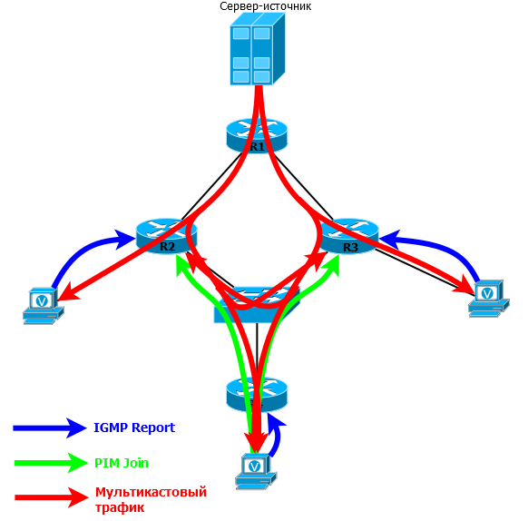
Since everything is being done for the sake of our beloved clients, then, starting with them, we will examine in detail the whole process.
1) Client 1 sends IGMP Report for group 224.2.2.4

2) R4 receives this request, realizes that there is a client behind the FE0 / 0 interface, adds this interface to the OIL and forms the entry (*, G).
")
Here you can see the upstream interface FE0 / 1, but this does not mean that R4 receives traffic for group 224.2.2.4. It only says that the only place he can get from now is FE0 / 1, because this is where RP is located. By the way, the neighbor who passed RPF-Check - R2: 10.0.2.24 is also indicated here. Expected.
R4 is called - LHR (Last Hop Router) - the last router in the path of multicast traffic, if you count from the source. In other words, it is the router closest to the receiver. For Customer1 , this is R4, for Customer2 , this is R5.
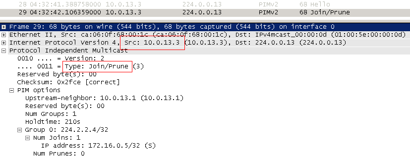
3) Since there is no multicast stream on R4 (he did not request it before), it forms the PIM Join message and sends it to RP (2.2.2.2).
")
PIM Join is sent by multicast to the address 224.0.0.13. “Towards RP” means through the interface that is specified in the routing table, as outbound for the address that is specified inside the packet. In our case, this is 2.2.2.2 - the RP address. Such a Join is also referred to as Join (*, G) and says: “It doesn’t matter who the source is, I need the traffic of the group 224.2.2.4”.
That is, each router on the path must process such a Join and, if necessary, send a new Join to the RP. (It is important to understand that if this group already exists on the router, it will not send above Join - it will simply add the interface from which Join came to OIL and start sending traffic).
In our case, Join went to FE0 / 1:

4) R2, after receiving Join, forms the entry (*, G) and adds the FE0 / 0 interface to the OIL. But Join is nowhere to send - he is already RP, but nothing is yet known about the source.
This way, RP will know where the customers are located.
If Client 2 also wants to receive multicast traffic for the same group, R5 will send PIM Join to FE0 / 1, because RP is behind it, receiving it, forms a new PIM Join and sends it to FE1 / 1 - where RP is located .
That is, Join travels node by node until it reaches RP or another router where there are already clients of this group.
So R2 - our RP - now knows that it has recipients for FE0 / 0 and FE1 / 0 for group 224.2.2.4.
And no matter how many of them are there - one for each interface or one hundred - the traffic flow will still be one per interface.
If we graphically depict what we received, it will look like this:

It resembles a tree remotely, doesn’t it? Therefore, it is called so - RPT - Rendezvous Point Tree . This is a tree with a root in RP, and whose branches extend to customers.
A more general term, as we mentioned above, is MDT — Multicast Distribution Tree — a tree along which a multicast stream spreads. Later you will see the difference between MDT and RPT.
5) Now we cut the server. As we discussed above, he is not worried about PIM, RP, IGMP — he just broadcasts. And R1 gets this thread. His task is to deliver a multicast to RP.
PIM has a special type of message - Register . It is needed in order to register the source of the multicast on the RP.
So, R1 receives multicast group flow 224.2.2.4:

")
R1 is FHR (First Hop Router) - the first router in the path of multicast traffic or closest to the source.
6) Next, it encapsulates each multicast packet received from the source into a unicast PIM Register and sends it straight to the RP.

Pay attention to the protocol stack. Above the unicast IP and PIM header is the original multicast IP, UDP and data.
Now, unlike all other PIM messages known to us, 2.2.2.2 is indicated in the recipient's address, and not the multicast address.
Such a package is delivered to the RP according to the standard rules of unicast routing and carries the original multicast packet, that is, this ... this is tunneling!
=====================Problem number 1
Scheme and initial configuration .
On the server 172.16.0.5, an application is running that can only transmit packets to the broadcast address 255.255.255.255, with the UDP receiver port 10999.
This traffic must be delivered to clients 1 and 2:
Client 1 in the form of multicast traffic with a group address of 239.9.9.9.
And in the client segment 2, in the form of broadcast packets to the address 255.255.255.255.
Details of the problem here .
=====================
7) RP receives the PIM Register, unpacks it and detects the traffic for the group 224.2.2.4 under the wrapper.
He immediately writes information about this into his multicast routing table:
")
There was a record (S, G) - (172.16.0.5, 224.2.2.4).
Unpacked RP packets further sends to RPT on the FE0 / 0 and FE1 / 0 interfaces, through which traffic reaches the clients.
In principle, this could be stopped. Everything works - customers get traffic. But there are two problems:
- Encapsulation and decapsulation processes are very costly for routers. In addition, additional headers increase the size of the packet, and it may simply not crawl into the MTU somewhere on the intermediate node (remember all the problems of tunneling ).
- If suddenly somewhere between the source and RP there are still recipients for the group, multicast traffic will have to go one way twice.
Take for example the following topology:

The traffic in the Register messages will first reach the RP via the R1-R42-R2 line, then the pure multicast will return via the R2-R42 line. Thus, on the line R42-R2 two copies of one traffic will go, albeit in opposite directions.

Therefore, it is better to transmit a pure multicast from the source to the RP, and for this you need to build a tree - Source Tree .
8) Therefore, the RP sends a PIM Join message to R1. But now it indicates for the group the address not of the RP, but of the source, learned from the Register message. This message is called Join (S, G) - Source Specific Join .

His goal is exactly the same as that of PIM Join (*, G) - to build a tree, only this time from source to RP.
Join (S, G) also extends node by node, just like regular Join (*, G). Only Join (*, G) tends to RP, and Join (S, G) to S - source. The recipient’s address is also a business address of 224.0.0.13 and TTL = 1.
If there are intermediate nodes, for example, R42, they also form an entry (S, G) and a list of downstream interfaces for this group and forward the Join further to the source.
The path that Join went from RP to the source turns into a Source Tree - a tree from the source. But the more common name - SPT - Shortest Path Tree - because the traffic from the source to the RP will follow the shortest path.
9) R1 received Join (S, G), adds the interface FE1 / 0, from where the packet came, to the list of downstream interfaces OIL and begins to broadcast pure multicast traffic there, uncluttered by encapsulation. The record (S, G) on R1 was already as soon as it received the first multicast packet from the Source Server.
")
According to the multicast constructed by the Source Tree, the RP is transmitted (and to all intermediate clients, if any, for example, R42).
But it must be kept in mind that Register messages were transmitted all this time and are transmitted until now. That is, in fact, R1 sends two copies of traffic now: one is a pure multicast on SPT, the other is encapsulated in a unicast Register.

First, R1 sends a multicast register - packet 231 . Then R2 (RP) wants to connect to the tree, sends the Join package 232 . R1 still some time while processes request from R2, sends multicast in Register ( packets with 233 on 238 ). Further, when the downlink interface is added to OIL on R1, it starts transmitting a pure multicast - packets 239 and 242 , but does not stop it yet and Register - packets 241 and 243 . And the pack 240 is R2 could not resist and once again asked to build a tree.
10) So, a clear multicast reaches RP. She understands that this is the same traffic that comes to Register, because the same group address, the same source address and from the same interface. In order not to receive two copies, he sends a uni-rim PIM Register-Stop to R1.

Register-Stop does not mean that R2 refuses traffic or does not recognize this source anymore, this only means that it is necessary to stop sending encapsulated traffic.
Next comes a bitter struggle - R1 continues to transmit the traffic accumulated in the buffer while the Register-Stop processes, and with the usual multicast and within Register messages:

But, sooner or later, R1 starts broadcasting only pure multicast traffic.

In preparation, I had, as it seemed to me, a logical question: well, why are all these tunneling, PIM Register? Why not deal with multicast traffic, as with PIM Join - send hop after hop with TTL = 1 in the direction of RP - it will come sooner or later? So would the tree be built at the same time without unnecessary gestures.
Here there are several nuances.
Firstly, the main principle of PIM SM is violated - to send traffic only to where it was requested from. No Join - No Tree !
Secondly, if there are no clients for this group, FHR will not know about it and will continue to send traffic on “its own tree”. Why such mindless use of bandwidth? In the world of communication, such a protocol simply would not have survived, just as PIM DM or DVMRP did not survive.
Thus, we have one large MDT tree for group 224.2.2.4 from the Source Server to Client 1 and Client 2 . And this MDT is made up of two pieces that were built independently of each other: Source Tree from source to RP and RPT from RP to customers. This is what distinguishes MDT from RPT and SPT. MDT is a fairly generic term for the multicast transmission tree in general, while RPT / SPT is its very specific form.
What to do if the server is already broadcasting, but there are still no clients? Will the multicast still litter the area between the sender and the RP?
No, in this case also help PIM Register-Stop. If the Register started receiving messages for some group on the RP, but there are no recipients for it, the RP is not interested in receiving this traffic, therefore, without sending PIM Join (S, G), the RP immediately sends Register-Stop to R1.
R1, having received Register-Stop and seeing that there is no tree for this group yet (no clients), begins to discard multicast traffic from the server.
That is, the server itself is not worried about this at all and continues to send the stream, but when it reaches the interface of the router, the stream will be dropped.
At the same time, the RP continues to store the record (S, G). That is, he does not receive traffic, but he knows where the source for the group is located. If recipients appear in the group, the RP finds out about them and sends to the source the Join (S, G) that builds the tree.
In addition, every 3 minutes R1 will try to re-register the source on the RP, that is, send the Register packets. This is necessary in order to notify the RP that this source is still alive.
Particularly inquisitive readers must ask a question - what about the RPF? After all, this mechanism checks the sender address of the multicast packet and, if the traffic is not sent from the correct interface, it will be dropped. In this case, the RP and the source may be behind different interfaces. So in our example for R3 RP - for FE1 / 1, and the source - for FE1 / 0.
The answer is predictable - in this case, not the source address, but RP is checked. That is, the traffic should come from the interface towards the RP.
But, as you will see later, this is also not an indestructible rule.
It is important to understand that RP is not a universal magnet - for each group there may be its own RP. That is, there may be two, three, and one hundred in the network — one RP is responsible for one set of groups, the other for another. Moreover, there is such a thing as Anycast RP and then different RPs can serve the same group.
=====================
Scheme and initial configuration .
Note to the topology : in this task, only the routers R1, R2, R3 are managed by the administrators of our network. That is, the configuration can only be changed on them.
Server 172.16.0.5 transmits multicast traffic to groups 239.1.1.1 and 239.2.2.2.
Configure the network so that traffic from group 239.1.1.1 is not transmitted to the segment between R3 and R5, and to all segments below R5.
But at the same time, the traffic of the group 239.2.2.2 should be transmitted without problems.
Details of the problem here .
=====================
Occam's razor or disabling unnecessary branches.
After the last client in the segment has unsubscribed, the PIM should cut off the extra RPT branch.
Let, for example, the only client on R4 turned off the computer. The router by IGMP Leave message or after three unanswered IGMP Query realizes that there are no more clients for FE0 / 0, and sends a PIM Prune message to the RP . The format is exactly the same as Join, but performs the opposite function.
The destination address is also 224.0.0.13, and the TTL is 1.

But the router that received the PIM Prune waits for a while before removing the subscription (usually 3 seconds - Join Delay Timer).
This is done for this situation:

In one broadcast domain 3 routers. One of them is higher and it is he who sends multicast traffic to the segment. This is R1. For both routers (R2 and R3), his OIL contains only one entry.
If R2 now decides to disconnect and sends PIM Prune, then it can substitute its colleague R3 - R1, after all, it will stop broadcasting to the interface altogether.
So, so that this does not happen, R1 and gives a timeout of 3 seconds. During this time, R3 must have time to react. Taking into account the network broadcasting, he will also receive Prune from R2 and therefore, if he wants to continue receiving traffic, he instantly sends the normal PIM Join to the segment, notifying R1 that he should not delete the interface.
This process is called Prune Override. R2 seemed to take over R1, seize the initiative.
SPT Switchover - RPT-SPT Switching
Until now, we mainly considered only Client 1 . Now let's turn to Client 2 .
At first, everything for him is identical to Client 1 - he uses RPT from RP, which we considered earlier. By the way, since both Client 1 and Client 2 use the same tree, this tree is called the Shared Tree — this is quite a common name. Shared tree = RPT.
Here is the multicast routing table on R5 at the very beginning, immediately after building the tree:
 SPT Switchover")
There is no record (S, G), but this does not mean that multicast traffic is not transmitted. Just the R5 doesn't care about who the sender is.
Pay attention to what path should go in this case traffic - R1-R2-R3-R5. Although the path is shorter R1-R3-R5.

And if the network is more complicated?

Somehow inaccurate.
The fact is that while we are tied to RP - it is the root of the RPT, only she first knows where everyone is. However, if you think about it, after the first multicast packet, all routers will know the source address along the traffic path, because it is indicated in the IP header.

Why don't someone send the Join itself to the source and optimize the route?
See the root. Such a switch can trigger the LHR (Last Hop Router)- R5. After receiving the first multicast packet from R3, R5 sends the already familiar Source Specific Join (S, G) to the FE0 / 1 interface, which is indicated in its routing table, as outgoing for the network 172.16.0.0/24.

Having received such a Join, R3 sends it not to the RP, as it did with the usual Join (*, G), but to the source (via the interface according to the routing table).
That is, in this case, R3 sends a Join (172.16.0.5, 224.2.2.4) to the FE1 / 0 interface.
Further, this Join falls on R1. And R1 by and large, no matter who sent it - RP or someone else - he just adds FE1 / 1 to his OIL for group 224.2.2.4.

At this point, there are two paths between the source and the receiver and R3 receives two streams.

Time to make a choice to trim too much. Moreover, it is R3 that does it, because R5 will not be able to distinguish between these two streams - they will both come through one interface.
As soon as R3 recorded two identical flows from different interfaces, it selects the preferred one according to the routing table. In this case, direct, better than through RP. At this point, R3 sends Prune (S, G) to the RP side, chopping off this RPT branch. And from this moment there is only one stream directly from the source.

Thus, PIM built SPT - Shortest Path Tree. It is the Source Tree. This is the shortest path from the client to the source. By the way, the tree from the source to RP, which we have already considered above, is essentially the very same SPT.
It is characterized by the record (S, G). If the router has such an entry, then it knows that S is the source for the G group and the SPT tree has been built.
The root of the SPT tree is the source and really want to say "the shortest path from the source to the client ." But this is technically incorrect, since the paths from the source to the client and from the client to the source may be different. Namely, a branch of the tree starts to be built from the client: the router sends PIM Join to the source / RP side and the RPF also checks the correctness of the interface when receiving traffic.
You remember that at the beginning of this paragraph on R5 there was only a record (*, G), now after all these events there will be two of them: (*, G) and (S, G) .
By the way, even if you look at the multicast routing table of R3 in the same second as you clicked Play in VLC, you will see that it already receives traffic from R1 directly, as indicated by the presence of a record (S, G).
That is, SPT Switchover has already happened - this is the default action on the equipment of many manufacturers - to initiate the switch after receiving the first multicast package.
Generally speaking, such a switch can occur in several cases:
- Never occur at all ( ip pim spt-threshold infinity command ).
- When a certain bandwidth utilization is reached ( ip pim spt-threshold X command ).
- Of course, immediately after receiving the first packet (default action or no ip pim spt-threshold X )
As a rule, the decision that it is time to take the LHR.
In this case, the RPF operation rule changes a second time — it checks the location of the source again. That is, of the two multicast streams - from RP and from the source - preference is given to traffic from the source.
DR, Assert, Forwarder
A few more important points when considering PIM.
DR - Designated Router .
This is a dedicated router that is responsible for sending service packets to the RP.
Source DR - is responsible for accepting multicast packets directly from the source and registering it with the RP.
Here is an example of the topology:

There is no need for both routers to send traffic to the RP, let them reserve each other, but there should be only one responsible person.
Since both routers are connected to the same broadcast network, they get PIM-Hello from each other. Based on it, they make their choice.
Hello PIM carries the priority value of this router on this interface.

The higher the value, the higher the priority. If they are the same, then the node with the highest IP address is selected (also from the Hello message).

If the other router (not DR) did not receive Hello from the neighbor during Holdtime (by default 105 s), it automatically assumes the role of DR.
In essence, Source DR is FHR - First Hop Router .
Receiver DR - the same as Source DR, only for recipients of multicast traffic - LHR (Last Hop Router) .
Example topology:

Receiver DR is responsible for sending to RP PIM Join. In the above topology, if both routers send Join, both will receive multicast traffic, but this is not necessary. Only DR sends Join. The second simply monitors the availability of DR.
Since the DR sends a Join, it will also broadcast traffic on the LAN. But then a natural question arises - what if the PIM DR was one and the IGMP Querier was different? And the situation is quite possible, because for Querier, the smaller the IP, the better, and for DR, on the contrary.
In this case, the DR is chosen for the router that is already Querier and this problem does not arise.

The rules for selecting Receiver DR are exactly the same as Source DR.
Assert and PIM Forwarder
The problem of two simultaneously transmitting routers can arise in the middle of a network where there are neither end clients nor sources — only routers.
This issue was very acute in PIM DM, where it was a completely ordinary situation due to the Flood and Prune mechanism.
But in PIM SM it is not excluded.
Consider such a network:

Here, the three routers are in the same network segment and, accordingly, are neighbors in the PIM. R1 acts as RP.
R4 sends PIM Join towards RP. Since this packet is multicast, it falls on both R2 and R3, and both of them after processing it add a downstream interface to the OIL.
There should be a DR selection mechanism, but there are other clients of this group on R2 and R3, and both routers will have to send PIM Join anyway.
When multicast traffic comes from a source on R2 and R3, it is transmitted to the segment by both routers and backed up there. PIM does not try to prevent such a situation - here it acts on the fact of a crime - as soon as the router receives multicast traffic from this group to its downlink interface for a specific group (from the OIL list), it understands that something is wrong - there is another sender in this segment.
Then the router sends a special message to the PIM Assert .
This message helps you choose PIM Forwarder.- the router that is entitled to broadcast in this segment.

Don't confuse it with PIM DR. First, PIM DR is responsible for sending PIM Join and Prune messages , and PIM Forwarder is responsible for sending traffic . The second difference is that PIM DR is always selected in any networks when establishing a neighborhood, and PIM Forwrder only when necessary - when multicast traffic is received from the interface from the OIL list.
RP selection
Above, for simplicity, we set the RP manually using the ip pim rp-address XXXX command .
And this is how the show ip pim rp command looked like :

But let's imagine a completely impossible situation in modern networks - R2 failed. This is all - finish. Client 2 will still work, since SPT Switchover has occurred, but everything new and everything that went through the RP will break, even if there is an alternative way.
Well, the load on the domain administrator. Imagine: manually killing at least one command on 50 routers (and for different groups there may be different RPs).
Dynamic RP selection allows you to avoid manual work and ensure reliability - if one RP becomes unavailable, the other will immediately enter into battle.
At the moment there is one generally accepted protocol that allows you to do this - Bootstrap . In previous times, Tsisk was promoted by a somewhat clumsy Auto-RP , but now it is hardly used, although Tsisk does not recognize this, and in show ip mroute we have an annoying rudiment as a group of 224.0.1.40.
We must actually do justice to the Auto-RP protocol. He was a salvation in the old days. But with the advent of open and flexible Bootstrap, he naturally lost his position.
So, suppose that in our network we want R3 to pick up RP functions in case of failure of R2.
R2 and R3 are defined as candidates for the role of RP - so they are called C-RP . On these routers we configure:
RX(config)interface Loopback 0 RX(config-if)ip pim sparse-mode RX(config-if)exit RX(config)#ip pim rp-candidate loopback 0 But while nothing is happening - the candidates do not yet know how to notify everyone about themselves.
To inform all multicast domain routers about existing RPs, the BSR mechanism is introduced - the BootStrap Router . Applicants may be several, as well as C-RP. They are called C-BSR respectively . They are configured in a similar way.
Let BSR we have one and for the test (exclusively) it will be R1.
R1(config)interface Loopback 0 R1(config-if)ip pim sparse-mode R1(config-if)exit R1(config)#ip pim bsr-candidate loopback 0 First of all, one main BSR is selected from all C-BSRs, which will fill everything. To do this, each C-BSR sends a multicast BootStrap Message (BSM) to the network to the address 224.0.0.13 - this is also a PIM protocol packet. It must be accepted and processed by all multicast routers and then sent to all ports where PIM is activated. BSM is not transmitted in the direction of something (RP or source), as opposed to PIM Join, but in all directions. This fan mailing helps to reach BSM in all corners of the network, including all C-BSRs and all C-RPs. In order for the BSM not to wander around the network indefinitely, the same RPF mechanism is used - if the BSM came from the wrong interface where the sender's network of the message is located, the message is discarded.

With the help of these BSM, all multicast routers determine the most worthy candidate based on priorities. As soon as C-BSR receives BSM from another router with a higher priority, it stops sending its messages. As a result, all have the same information.

At this stage, when BSR is chosen, due to the fact that its BSM has already spread across the entire network, C-RPs know its address and unicast send Candidte-RP-Advertisement messages to it , in which they carry a list of the groups they serve - called group-to-RP mapping . BSR aggregates all these messages and creates an RP-Set - information table: which RPs each group serves.

Then the BSR sends the same BootStrap Message in the old fan manner, which this time contains the RP-Set. These messages successfully reach all multicast routers, each of which independently chooses which RP to use for each particular group.

BSR periodically makes such mailings so that, on the one hand, everyone knows that the information on the RP is still relevant, and on the other, C-BSR was aware that the main BSR itself is still alive.
RP, by the way, also periodically sends its announcements to Candidate-RP-Advertisement on BSR.
In fact, all that needs to be done to configure the automatic selection of RPs is to specify a C-RP and specify a C-BSR — not so much work, PIM will do the rest.
As always, in order to improve reliability, it is recommended to specify Loopback interfaces as candidates.
Concluding the chapter of PIM SM, let us once again mark the most important moments.
- Normal unicast connectivity should be provided using IGP or static routes. This is the basis of the RPF algorithm.
- The tree is built only after the appearance of the client. It is the client that initiates the construction of the tree. No customer - no tree.
- RPF helps to avoid loops.
- All routers should be aware of who is RP - only with its help you can build a tree.
- The RP point can be specified statically, or it can be selected automatically using the BootStrap protocol.
- RPT — RP — Source Tree — RP. RPT SPT — .
We also list all types of trees and messages that we now know.
MDT - Multicast Distribution Tree . General term describing any tree of multicast transmission.
SPT - Shortest Path Tree . The tree with the shortest path from the client or RP to the source. In PIM DM there is only SPT. In PIM SM, SPT can be from source to RP or from source to destination after the SPT Switchover has occurred. It is denoted by the entry (S, G) - the source is known for the group.
Source Tree is the same as SPT.
RPT - Rendezvous Point Tree . Tree from RP to recipients. Used only in PIM SM. Denoted by the entry (*, G) .
Shared Tree- the same as the RPT. It is so called because all clients are connected to the same common tree with a root in RP.
Types of messages PIM Sparse Mode:
Hello - to establish a neighborhood and maintain this relationship. Also needed to select DR.
Join (*, G) - request to connect to the tree of group G. It does not matter who is the source. Sent toward RP. With their help, the RPT tree is built.
Join (S, G) - Source Specify Join. This is a request to connect to a tree of group G with a specific source, S. It is sent to the source side, S. They are used to build an SPT tree.
Prune (*, G) - request to disconnect from a tree of group G, whatever sources for it were. Sent toward RP. This is how the RPT branch is trimmed.
Prune (S, G)- request to disconnect from the tree of the group G, whose root is the source S. It is sent to the source. This is how the SPT branch is trimmed.
Register is a special message within which a multicast is transmitted to the RP until the SPT is built from the source to the RP. Transmitted by unicast from FHR to RP.
Register-Stop - sent by unicast from RP to FHR, ordering to stop sending multicast traffic encapsulated in Register.
Bootstrap - BSR mechanism packages that allow you to select a router for the role of BSR, and also transmit information about existing RPs and groups.
Assert is a message for selecting PIM Forwarder so that two routers do not send traffic to one segment.
Candidate-RP-Advertisement- a message in which the RP sends to the BSR information about which groups it serves.
RP-Reachable - a message from the RP with which it notifies everyone of its availability.
* There are other types of messages in PIM, but these are details *
And now let's try to abstract from the details of the protocol? And then its complexity becomes apparent.
1) Definition of RP,
2) Register the source to RP,
3) Switch to SPT tree.
Many protocol states, many entries in the multicast routing table. Can I do something about this?
Today, there are two diametrically opposed approaches to simplifying PIM: SSM and BIDIR PIM.
SSM
All that we have described so far is ASM - Any Source Multicast . Clients do not care who is the source of traffic for the group - the main thing is that they receive it. As you remember in the message IGMPv2 Report it is requested just to connect to the group.
SSM - Source Specific Multicast - an alternative approach. In this case, the clients specify the group and source when connecting.
What does this give? Nothing more: the ability to completely get rid of RP. LHR immediately knows the source address - there is no need to send Join to RP, the router can immediately send Join (S, G) in the direction of the source and build an SPT.
So we get rid of
- RP search (Bootstrap and Auto-RP protocols),
- ( , )
- SPT.
Since there is no RP, then there is no RPT, respectively, there will no longer be any (*, G) entries on any router — only (S, G).
Another problem that is solved with the help of SSM is the presence of several sources. In ASM, it is recommended that the multicast group address be unique and only one source broadcast to it, since several streams in the RPT tree will merge, and the client, receiving two streams from different sources, probably will not be able to parse them.
In SSM, traffic from various sources is distributed independently, each in its own SPT tree, and this is no longer a problem, but an advantage — several servers can broadcast simultaneously. If suddenly the client began to record losses from the main source, he can switch to the backup one, without even re-requesting it - he already received two streams.
In addition, a possible attack vector in a network with activated multicast routing is an attacker's connection of his source and generating a large amount of multicast traffic that will overload the network. In SSM this is almost impossible.
For SSM, a special range of IP addresses is allocated: 232.0.0.0/8.
On routers to support SSM, PIM SSM mode is enabled.
Router(config)# ip pim ssm IGMPv3 and MLDv2 support pure SSM.
When used, the client can
- Request a connection to a simple group, without specifying sources. That is, it works like a typical ASM.
- Request a connection to a group with a specific source. You can specify several sources - a tree will be built before each of them.
- Request a connection to the group and specify a list of sources from which the client would not want to receive traffic
IGMPv1 / v2, MLDv1 does not support SSM, but there is such a thing as SSM Mapping . At the nearest client router (LHR), each group is assigned a source address (or several). Therefore, if there are clients on the network that do not support IGMPv3 / MLDv2, SPT will be built for them, not RPT, due to the fact that the source address is still known.
SSM Mapping can be implemented as a static setting on the LHR, or by accessing the DNS server.
The problem with SSM is that customers must know the source addresses in advance — they are not signaled by any signaling.
Therefore, SSM is good in those situations when there is a certain set of sources on the network, their addresses are obviously known and will not change. And client terminals or applications are tightly tied to them.
In other words, IPTV is a very suitable environment for SSM implementation. This well describes the concept of One-to-Many - one source, many recipients.
BIDIR PIM
And what if the network sources can appear spontaneously here and there, broadcast to the same groups, quickly stop transmitting and disappear?
For example, this situation is possible in online games or in the data center, where data is replicated between different servers. This is a Many-to-Many concept - many sources, many clients.
How does a regular PIM SM look at it? It is clear that inert PIM SSM is not suitable here?
Just think what chaos will start: endless registration of sources, rebuilding of trees, a huge number of records (S, G) living for several minutes due to protocol timers. Bidirectional PIM
( Bidirectional PIM, BIDIR PIM) comes to the rescue). Unlike SSM, on the contrary, they completely abandon SPT and (S, G) records - only the Shared Tree with the root in RP remains.
And if in a normal PIM, a tree is one-way - the traffic is always sent from the source down the SPT and from the RP down the RPT - there is a clear division, where the source is where the clients are, then in bidirectional from the source the traffic to the RP is also sent up along the Shared Tree over the same one that traffic flows down to customers.
This eliminates the registration of the source on the RP - the traffic is transmitted unconditionally, without any signaling or state changes. Since there are no SPT trees at all, SPT Switchover does not occur either.
For example:

Istochnik1 began airing the network traffic simultaneously with the group 224.2.2.4 Istochnikom2 . Flows from them just poured towards RP. Some of the clients that are nearby began to receive traffic immediately, because the routers have an entry (*, G) (there are clients). The other part receives traffic on the Shared Tree from the RP. And they receive traffic from both sources simultaneously.
That is, if you take a speculative network game for example, Source1 is the first player in the shooter who took the shot, and Source2 is another player who took a step to the side. Information about these two events spread throughout the network. And every other player ( Recipient ) should learn about both of these events.
, , RP — , , RP . ? : BIDIR PIM , , , , . RP .
Notice that the image above between R5 and R7 has a straight line, much shorter than the path through the RP, but it was not used because Join goes to the RP side according to the routing table in which the path is not optimal.
It looks pretty simple - you need to send multicast packets in the direction of RP and that's all, but there is one nuance that spoils everything - RPF. In the RPT tree, it requires that traffic come from RP and not otherwise. And here he can come from anywhere. Of course, we cannot take and abandon the RPF - this is the only mechanism that avoids the formation of loops.
Therefore, the concept of DF - Designated Forwarder is introduced in BIDIR PIM. In each network segment, on each line, the router whose route to RP is better is chosen for this role.
This is also done on those lines where customers are directly connected. In BIDIR PIM, the DF is automatically DR.

The OIL list is generated only from those interfaces on which the router was selected for the DF role.
The rules are pretty transparent:
- If the PIM Join / Leave request arrives on the interface that is DF in this segment, it is passed to the RP side according to standard rules.
Here, for example, R3. If requests come to DF interfaces that are marked with a red circle, it sends them to the RP (via R1 or R2, depending on the routing table). - PIM Join/Leave DF , .
, , R1 R3, IGMP Report. R1 , DF ( ), . R3 , DF. R3 , , . - DF , OIL RP.
, 1 . R4 DF DF- — RP, — , RP . R3 — OIL — R5, - RPF, — RP. - DF , OIL, RP.
, 2 , RP RPT. R3 R1, R2 — R4 R5.
Thus, DF ensures that only one copy of the multicast packet will be sent to the RP as a result and the formation of loops is excluded. At the same time, the common tree in which the source is located, naturally, will receive this traffic before it reaches the RP. RP, according to the usual rules, will send traffic to all OIL ports, in addition, where the traffic came from.
By the way, there is no need for more messages in Assert, because DF is selected in each segment. Unlike DR, he is responsible not only for sending Join to RP, but also for sending traffic to a segment, that is, a situation where two routers send traffic to the same subnet is excluded from BIDIR PIM.
Perhaps the last thing to say about the bidirectional PIM is the features of RP. While in PIM, SM RP performed a very specific function - registration of the source, then in BIDIR PIM RP - this is some very conditional point towards which traffic on the one hand tends and Join from clients on the other. No one should perform decapsulation, request the construction of an SPT tree. Just on some router, suddenly the traffic from the sources starts to be transmitted to the Shared Tree. Why do I say "at some"? The fact is that in BIDIR PIM RP is an abstract point, not a specific router, a non-existent IP address can act as an RP address - the main thing is that it is routable (this RP is called Phantom RP ).
All PIM terms can be found in the glossary .
Multicast channel level
So, behind the long working week with lack of sleep, processing, tests - you have successfully implemented multicast and satisfied customers, director and sales department.
Friday is not the worst day to inspect the creation and allow yourself a pleasant stay.
But your afternoon nap suddenly disturbed the tech support call, then another one and more - nothing works, everything broke. Check - there are losses, breaks. Everything converges on one segment of several switches.
We uncovered SSH, checked the CPU, checked the utilization of the interfaces and the hair on end - loading under almost 100% on all interfaces of one VLAN. A loop! But where would she come from if no work was done? 10 minutes of checking and you noticed that on the upstream interface to the core you have a lot of incoming traffic, and on all downstream clients - outgoing traffic. For the loop, this is also characteristic, but somehow suspicious: they introduced a multicast, they did not do any work on switching, and the jump was only in one direction.
We checked the list of multicast groups on the router - and there is a subscription to all possible channels and all to one port - naturally, the one that leads to this segment.
The meticulous investigation revealed that the client’s computer is infected and sends IGMP Query to all multicast addresses in a row.
Packet losses began because the switches had to pass through a huge amount of traffic. This caused an overflow of interface buffers.
The main question is why did the traffic of one client start being copied to all ports?
The reason for this lies in the nature of multicast MAC addresses. The fact is, the multicast IP address space is mapped in a special way into the multicast MAC address space. And the snag is that they will never be used as the source MAC address, and therefore will not be examined by the switch and listed in the MAC address table. And what about a switch with frames whose destination address has not been studied? He sends them to all ports. What happened.
This is the default action.

Multicast MAC Addresses
So what recipient MAC addresses are put in the Ethernet header of such packets? Broadcast? Not.There is a special range of MAC addresses to which multicast IP addresses are mapped.
These special addresses start like this: 0x01005e and the next 25th bit should be 0 ( try to answer why ). The remaining 23 bits (remember, there are only them in the MAC address 48) are transferred from the IP address.
Here lies some not very serious, but a problem. The range of multicast addresses is determined by the mask 224.0.0.0/4, this means that the first 4 bits are reserved: 1110, and the remaining 28 bits may vary. That is, we have 2 ^ 28 multicast IP addresses and only 2 ^ 23 MAC addresses — 5 bits are not enough to display 1 in 1. Therefore, the last 23 bits of the IP address are taken and one-to-one are transferred to the MAC address, the remaining 5 bits are discarded.

In fact, this means that 2 ^ 5 = 32 IP addresses will be displayed in one multicast MAC address. For example, groups 224.0.0.1, 224.128.0.1, 225.0.0.1 and so on until 239.128.0.1 will all be mapped to one MAC address 0100: 5e00: 0001.
If you take a streaming video dump as an example, you can see:

IP address is 224.2.2.4, MAC address: 01: 00: 5E: 02: 02: 04.
There are also other multicast MAC addresses that are not related to IPv4 multicast ( click ). All of them, by the way, are characterized by the fact that the last bit of the first octet is 1.
Naturally, such a MAC address cannot be configured on any network card, so it will never be in the Source MAC field of an Ethernet frame and never get into table of MAC addresses. So these frames should be sent as anyUnknown Unicast to all ports VLAN'a.
All that we considered before is quite enough to fully transmit any multicast traffic from streaming video to stock quotes. But will we really put up with such a disgrace in our almost perfect world, as the broadcast of what could be passed on to the elect?
Not at all. Especially for perfectionists, the IGMP-Snooping mechanism was invented .
Igmp-snooping
The idea is very simple - the switch "listens" to IGMP packets passing through it.
For each group separately, it maintains a table of ascending and descending ports.
If the IGMP Report for the group came from the port, then the client is there, the switch adds it to the list of descending for this group.
If IGMP Query for the group came from the port, then the router is there, the switch adds it to the ascending list.
Thus, a multicast traffic transmission table at the data link layer is formed.
As a result, when a multicast stream comes from above, it is copied only to downstream interfaces. If there are only two clients on the 16-port switch, only the traffic will be delivered to them.

The genius of this idea ends when we think about its nature. The mechanism assumes that the switch should listen on traffic at the 3rd level.
However, IGMP-Snooping is in no comparison with NAT in the degree of ignoring the principles of network interaction. Moreover, besides saving resources, it carries a lot of less obvious possibilities. And in general, in the modern world, a switch that can peek inside IP is not an exceptional phenomenon.
=====================
.
172.16.0.5 239.1.1.1, 239.2.2.2 239.0.0.x.
, :
— 1 239.2.2.2. 239.0.0.x.
— 2 239.1.1.1. 239.0.0.x.
.
=====================
IGMP Snooping Proxy
An inquisitive reader may have a question about how IGMP Snooping recognizes all client ports, given that only one fastest client is responding to IGMP Query, as we said above. It's very simple: IGMP-Snooping does not allow Report messages to go between clients. They are sent only to the upstream ports to the routers. Not seeing Report from other recipients of this group, the client is obliged to respond to the Query within Max Response Time specified in this Query.
As a result, the network for 1000 nodes per IGMP Query within seconds 10 (the usual value of Max Response Time) will come to 1000 Reports for the router. Although it would be enough for him and one for each group.
And it happens every minute.
In this case, you can configure proxying IGMP requests. Then the switch does not just "listen" to passing packets, it intercepts them.
The rules of IGMP-Snooping may vary for different manufacturers. Therefore, we will consider them conceptually:
1) If the very first Report request for a group arrives at the switch, it is sent up to the router, and the interface is added to the drop-down list. If such a group already exists, the interface is simply added to the list of descending ones, and the Report is destroyed.
2) If the latest Leave comes to the switch, that is, there are no other clients, this Leave will be sent to the router, and the interface will be removed from the list of descending. Otherwise, the interface is simply deleted, Leave is destroyed.
3) If IGMP Query arrives from the router, the switch intercepts it, sends in response IGMP Report for all groups that currently have recipients.
And further, depending on the settings and the manufacturer, either the same Query is sent to all client ports, or the switch blocks the request from the router and acts as Querier itself, periodically polling all recipients.
Thus, the share of unnecessary service traffic on the network and the load on the router are reduced.
Multicast VLAN Replication
Short for MVR . This is the mechanism for those providers who practice VLAN-per-user , for example.
Here is a typical example of a network where MVR is vital:

5 clients in different VLANs, and everyone wants to receive multicast traffic from one group 224.2.2.4. At the same time, customers must remain isolated from each other.
IGMP-Snooping takes into account, of course, VLANs. If five clients in different VLANs request one group, this will be five different tables. Accordingly, 5 requests to connect to the group go to the router. And each of the five subinterfaces on the router will be added separately to the OIL. That is, having received 1 stream for the group 224.2.2.4, it will send 5 copies, despite the fact that they all go into one segment.

To solve this problem, Multicast VLAN Replication was developed.
An additional VLAN is introduced - Multicast VLAN - in it, accordingly, a multicast stream will be transmitted. It is “forwarded” directly to the last switch, where traffic from it is copied to all client interfaces that want to receive this traffic — this is replication.
Depending on the implementation, replication from Multicast VLAN can be done in a User-VLAN or to certain physical interfaces.

And what about IGMP messages? Query from the router, of course, comes via a multicast VLAN. The switch sends them to the client ports. When Report or Leave comes from a client, the switch checks from where it is (VLAN, interface) and, if necessary, redirects to a multicast VLAN.
Thus, the normal traffic is isolated and still goes to the router in the user VLAN. And multicast traffic and IGMP packets are transmitted to the Multicast VLAN.
On Cisco hardware, MVR and IGMP Snooping are configured independently. That is, you can turn off one and the second will work. In general, MVR is based on IGMP Snooping and on switches from other manufacturers for MVR operation it may be necessary to enable IGMP Snooping.
In addition, IGMP-Snooping allows you to filter traffic on the switches, limit the number of groups available to the user, enable IGMP Querier, static configuration of the upstream ports, permanent connection to a group (this scenario is in the accompanying video ), quick response to the topology change by sending additional Query, SSM-Mapping for IGMPv2, etc.
Finishing the conversation about IGMP-Snooping, I want to repeat - this is an optional functionality - everything will work without it. But this will make the network more predictable, and the engineer’s life will be calmer.
However, all the advantages of IGMP Snooping can be wrapped against themselves. One such outstanding case can be read on the link .
By the way, the same Cisco has CGMP protocol - an analogue of IGMP, which does not violate the principles of the switch, but it is proprietary and not to say that it is widespread.
So, my tireless reader, we are approaching the end of the issue and finally want to show how the client’s IPTV service can be implemented.
The easiest way to which we have already addressed this article more than once is to launch a player that can receive a multicast stream from the network. On it, you can manually set the IP address of the group and enjoy the video.
Another software option that is often used by providers is a special application, usually a very custom one, in which a set of channels used in the provider’s network is sewn up. There is no need to set something manually - you just need to switch channels with buttons.
Both of these methods make it possible to watch streaming video only on a computer.
The third option allows you to use the TV, and as a rule, any. To do this, in the client's house puts the so-called Set-Top-Box (STB) - a box installed on the TV. This is a trunk link that connects to the subscriber line and divides the traffic: it sends a normal unicast to Ethernet or WiFi so that customers have access to the Internet, and the multicast stream is transmitted to the TV via cable (DVI, RGB, antenna, etc.).
Often, by the way, you can see ads where the provider offers their set-top boxes for connecting to television - these are the very STB
=====================
( , ).
:
-, — , .
.
, :
1. , ?
2. , , , ?
, .
.
=====================
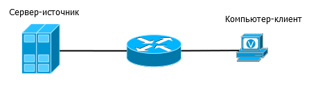
In the article, inter-domain routing of multicast traffic ( MSDP , MBGP , BGMP ), load balancing between RP ( Anycast RP ), PGM , proprietary protocols remained intact . But, I think, having this article as a starting point, it’s easy to figure out the rest.
All terms related to multicast can be found in the lookmeup glossary .
For assistance in preparing the article, thanks to JDima ...
For technical support, thanks to Natasha Samoylenko .
KDPV was painted by Nina Dolgopolova - a wonderful artist and friend of the project.
In the pool of articles SDSM still a lot of interesting until the end, so you do not need to bury the cycle due to the long lack of release - with each new article the complexity increases significantly. Ahead almost all MPLS, IPv6, QoS and network design.
As you may have noticed, linkmeup has a new project - a glossary lookmeup (yes, we have a fantasy close by). We hope that this glossary will be the most comprehensive reference for communications terms, so we will be glad to any help in filling it out. Email us at info@linkmeup.ru.
Stay tuned .
Source: https://habr.com/ru/post/217585/
All Articles