The index of the sequence of assembly operations. Improving the productivity of workers in assembly plants with a laser pointer

A few years ago I had a chance to work for some time in one very small company, which was engaged, among other things, in the manufacture of various electrical control panels, in the assembly of which I also had to participate. Work tedious in itself, but also the production - small-scale, and even with modifications within the series. In fact, it turned out the assembly of individual products on the appropriate set of documentation.
Naturally, it would be difficult to memorize the assembly sequence, so each step was recorded in the assembly instructions, and at each assembly step it was necessary to check the instructions, which took considerable time.
Moreover, with this method of production, when one person fully assembles the product, his head is occupied more than ten people who each perform their operation on the conveyor, so the likelihood of errors during assembly due to carelessness or fatigue increases.
')
The company management encouraged employees for performance proposals aimed not at increasing productivity, so I started looking for where it could be increased, and it was precisely the assembly time of the electrical panel that, it seemed to me, could be significantly accelerated.
Over the years, I don’t remember at what point the idea came, that you can speed up the assembly process with the help of a device located above the assembly table, which would include a conventional laser pointer mounted on a movable suspension controlled by a microcontroller, with its red dot the sequence of connecting the wires to the terminals of the various blocks in the shield.
Thus, following the light point, the collector would make all the necessary connections in the shield, without being distracted by viewing the documentation.
Further, it is clear that all the wires are different, and the assembler uses a different tool (also strictly according to the instructions). It's simple. All the wires, blocks and components from which the shield is assembled are laid out in containers marked with indicator LEDs. The tools are also laid out according to their own places marked with indicator LEDs.
In the course of the assembly process, according to the program, the LED at the required container turns on and the laser light point is supplied to the connection point of the wire in the shield. The collector takes the wire from this container, connects the wire to the right place and proceeds to the next step by pressing the button located on the device or on the instrument. The light point is transferred to the next connection, the collector connects the second end of the wire, etc. If you need a tool change, an audible alarm is used and the LED turns on where the desired tool lies. So, in general terms, the system should work.
Actually, I can not say that the device really speeds up the assembly of products, since I assembled a simplified, demonstrative version of my device a little later, when I was no longer working in that company, and it didn't make much sense to design it, and it wasn’t possible to check the device in practice. But the interest took its toll, and now I have such an incomprehensible device for the uninitiated - an index of the sequence of assembly operations.
The principle of work with the index of the sequence of assembly operations
All commands for the assembly of the shield, such as the trajectory of the laser beam, turning on the indicators of containers, turning on the sound signals, are recorded on the SD card to a file. The file can contain up to 100 assembly sequences selected by buttons on the front panel.
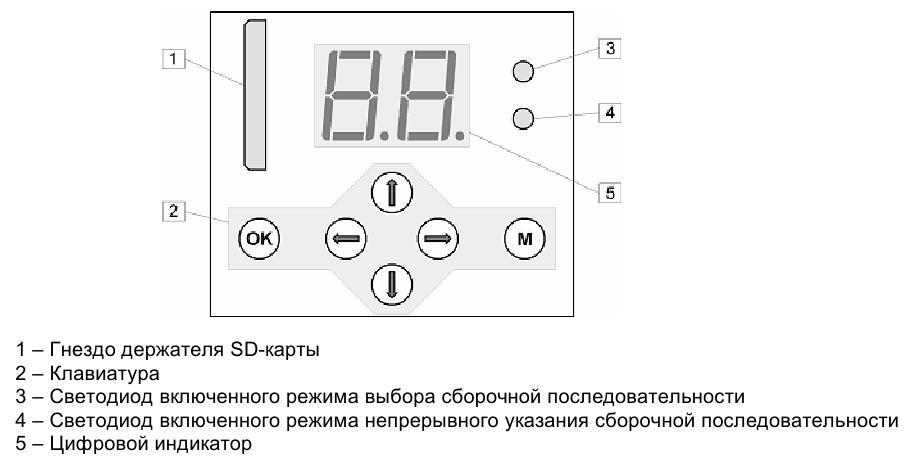
After turning on the device and initializing the SD card, which is well described in habrahabr.ru/post/213803 , the device enters the centering mode of the laser beam. If necessary, the ray is applied to the marked center on the assembly table with the arrow buttons and fixed by pressing the OK button. After, use the up / down arrow buttons to select the assembly sequence and start it by pressing the right arrow button. The sequence starts in a step-by-step mode, i.e. after each assembly operation, you need to press the right arrow button to go to the next step.
To enable the mode of continuous indication of the assembly sequence, press the M button. The LED of continuous indication of the assembly sequence will light up. To return to step mode, press the M button again.
There is a mode for recording coordinates of points (up to 256 points) on an SD card. To do this, turn on the device while holding the OK button and release the button. Then, using the arrow buttons, successively bring the laser beam to the desired location of the finished product installed on the assembly table, and fix the position of the beam by pressing the OK button. The value of the digital indicator will increase by one and display the number of the next point to record. By pressing the M button, the coordinates of the fixed points are recorded on the SD card in a file, which can then be used with the editor of the assembly sequence.
Design
The main difficulty in the manufacture of amateur constructions is the manufacture of the body and in general, any mechanical parts. As the walls I used a metal profile of 60x27 mm. The frame of the device, which serves simultaneously as the frame of the laser suspension, is literally welded and riveted from metal parts.
Suspension mobility is implemented using two DC motors.
The first engine turns a threaded shaft through a gear-reduction gear, on which a rectangular nut moves, one side rubbing against a wall running along the shaft, which prevents the nut from spinning.
The laser is mounted on a lever, with one end sitting on a fixed axis with respect to the engine, and the other end abutting with a spring on the nut.
Thus, the translational motion of the nut is converted into an angular deviation of the laser left-right.
In the same way, the second motor deflects the first motor together with the laser in the perpendicular direction relative to the laser deflection direction of the first motor, i.e. back and forth.
(Here, a flat plate is located along the shaft along the entire length, the pushing nut has a slot into which this plate is inserted.)
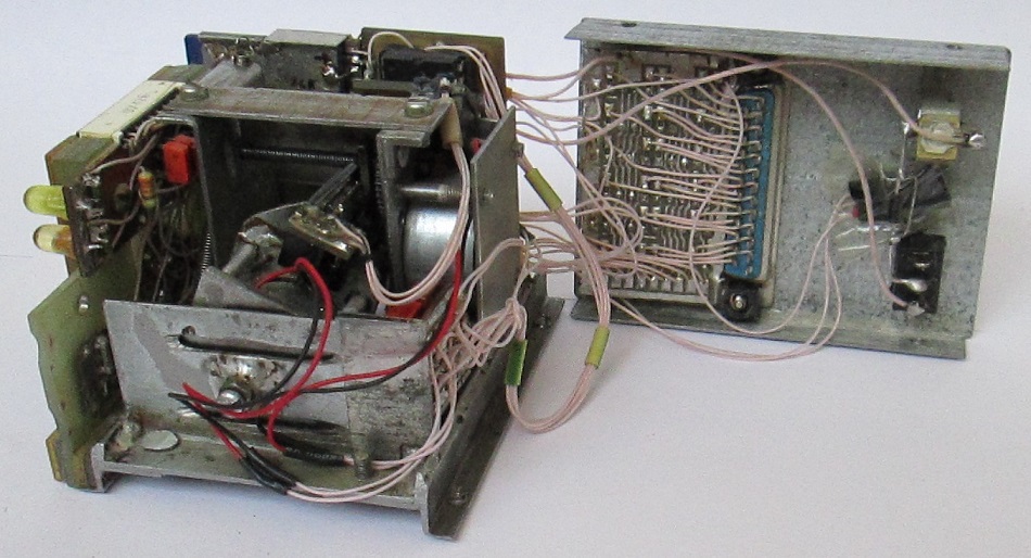
Motorized suspension of a laser pointer in easy parsing.

The plane of large gears passes through the gap between the IR diode and the phototransistor. Holes are made in the gears, opening periodically the light flux to the phototransistor, the pulses from which are fed to the inputs of the microcontroller, which counts these pulses and thus determines the current position of the laser.
The engine power board is also attached to the frame. The board is soldered to a tin plate folded in half in the form of a clip, which is put on a free frame element.
The rest of the construction is assembled around this frame of a motorized suspension. This is a front panel with control buttons, a display and a self-made slot for an SD card (it turned out to be an intractable problem to buy ready at that time), a board with a microcontroller on the socket, and an array of control LEDs mounted on the back cover from the inside.
Piezo emitter crammed into randomly remaining free space and practically does not hang out.
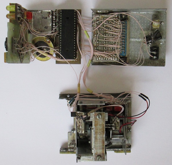
Attached to the bottom of the frame is a photo receiver of the external button for the transition to the next step of assembly operations.
A power connector, a power switch and a connector for connecting LED indicator arrays are brought to the back wall.

Circuitry

The device is controlled by a microcontroller PIC18F452.
Work with the SD card is carried out using the SPI protocol.
The tone of the sound signal is set by the PWM module.
The display is dynamic, according to a typical scheme, combined with a keyboard. A seven-segment two-digit LED indicator with marking BD-A51289 is used.
Motor drivers - a pair of transistors KT315 / KT361, included emitter followers. The current consumption of the engines turned out ~ 50mA.
The RF-300C motors, according to the specification, are rated at 5.9V, but work quite normally even at a voltage reduced to 3.6V.
The above-mentioned phototransistors of the sensors of the angle of deviation of the laser are taken from a VM-12 video recorder, some IR diodes are of dark blue color. Perfectly suited instead of miniature incandescent bulbs used in a VCR.
LED matrixes 8x8 = 64 for containers with shield parts and 4x4 = 16 for tools used in assembling require 24 power lines, therefore, an expansion circuit of an 8-bit microcontroller port on three 74HC374 registers is used.
The remote button to go to the next step of the assembly operation is assumed to be installed on each tool used. The transmission of a button press to the device takes place via the IR channel.
The TSOP-1736 module, designed for use in televisions and operating at a frequency of 36 kHz, is used as a photo-receiver. The multivibrator of the remote button unit is tuned to the same frequency. The TSOP-1736 has an open collector output, so it is directly connected in parallel to the next step button on the device itself.
Powered by an external + 5V source, connected through a connector on the back of the device.
Command system
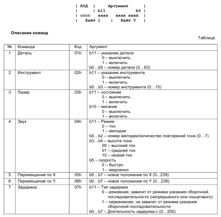
All commands are double byte. The upper 4 bits of the first byte is the command code. The remaining 12 bits are an argument.
Total used 7 teams.
Assembly sequence editor
Editor simple, written in haste.
The coordinates of the points recorded earlier in the board are loaded into the panel on the right.
The command to move the light point to a specific position is selected from this panel, the remaining commands are set from the left panel. In this case, the commands of the assembly sequence are displayed in plain text in the middle panel, where one line corresponds to one command. The string consists of a command mnemonic and an explanatory comment. The editor converts the mnemonic to a code for writing to the SD card, which is added to the file of the set of assembly sequences, which is read by the device microcontroller during operation.
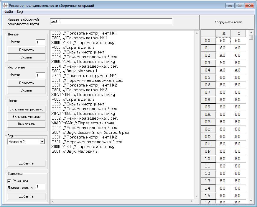
In the example in the screenshot, the actions are coded: take part # 1 and fix it with tool # 1 at two points, then change tool # 1 to number 2, take part # 2 and fix it at three points. Mode delays allow you to normalize the time of operations. The unreachable delay is used when changing tools to momentarily indicate where to put the tool that was just used. You do not need to press the button to move to the next step.
It also works
Video work on the above program.
Conclusion
I note once again that the development is rather ancient. It seems that now the development of the topic touched is directed towards the use of augmented reality technologies, such as here .
I did not give any codes, because, firstly, they are lost, and, just in case, secondly, if someone suddenly wants to repeat this particular idea, then in any case it will be a completely different implementation, on a modern elemental base. , with more accurate mechanics, 32-bit controller, large screen, access to the network, etc., etc.
Source: https://habr.com/ru/post/217343/
All Articles