Viz - New 3D visualization module in the OpenCV library

Good afternoon, today's blog post I want to devote to the review of the new module for 3D visualization Viz in the OpenCV library , in the design and implementation of which I participated. Perhaps I should introduce myself here, my name is Anatoly Baksheev , I have been working for Itseez , I have been using the OpenCV library for 7 years now, and I am developing and developing it together with my colleagues.
What relation does 3D visualization have to computer vision, you ask, and why do we even need such a module? And you will be right, if you look at computer vision as an area that works with images. But we live in the 21st century, and the field of application of computer vision has gone far beyond just image processing, highlighting object boundaries or face recognition. Science and technology have already learned in a more or less acceptable quality to measure our three-dimensional world. This was facilitated by the appearance of cheap Kinect- type sensors on the market a few years ago, which at that time allowed, with good accuracy and speed, the representation of a scene as a three-dimensional colored point cloud, and progress in the field of 3D reconstruction of the data from a series of images, and even mobile technologies, where an integrated gyroscope and accelerometer greatly simplifies the task of evaluating the movement of a mobile device camera in the 3D world, and hence the accuracy of scene reconstruction.
All this prompted the development of various methods and algorithms that work with 3D data. 3D segmentation, 3D noise filtering, 3D recognition of objects by shape, 3D face recognition, 3D body posture tracking, or hand gestures recognition. You probably know that when Kinect for XBox went on sale, Microsoft provided the developers of the SDK game to determine the position of the human body, which led to the emergence of a large number of games with an interesting interface - when, for example, the game character repeats the movements of the player facing Kinect . The results of such 3D algorithms must somehow be visualized. These are three-dimensional trajectories, reconstructed geometry, or, for example, the calculated position of a human hand in 3D. Also, such algorithms must be debugged, often visualizing intermediate data in the process of convergence of the developed algorithm.
')
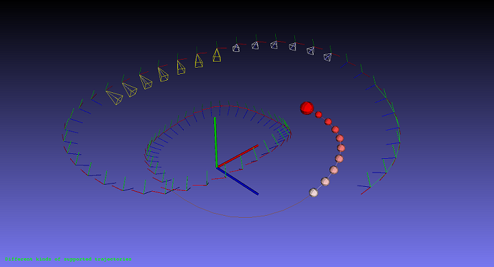
Various ways to display camera paths in OpenCV Viz
Thus, once the vector of developments shifts in the 3D area, in OpenCV there will be more and more algorithms that work with 3D data. And once there is such a trend, we hasten to create a convenient infrastructure for this. The Viz module is the first step in this direction. OpenCV has always been a library containing a very convenient base, on the basis of which algorithms and computer vision applications were developed. Convenient both because of the functionality, since it includes almost all the most frequently used operations for manipulating images and data, and because of the carefully developed and tested API for years (containers, basic types and operations with them), allowing for very compact implementation computer vision techniques, saving developer time. We hope that Viz meets all these requirements.
For the impatient, here is a video demonstrating the capabilities of the module.
Viz philosophy
The idea of creating such a module came to me when I somehow had to debug one algorithm of visual odometry ( vslam ), under conditions of limited time, when I felt in my own skin how such a module would help me and what functionality I would like to see in it . Yes, and colleagues said that it would be healthy to have such a module. Everything led to the beginning of its development, and then bringing it to a more or less mature state together with Ozan Tonkal , our Google Summer Of Code student. Work on improving Viz'a and is now.
The design idea is that it would be nice to have a system of three-dimensional widgets, each of which could be drawn in a 3D visualizer, simply by passing the position and orientation of this widget. For example, a point cloud coming from Kinect is often stored in a coordinate system related to the camera position, and for visualization it is often necessary to convert all point clouds taken from different camera positions into some kind of global coordinate system. And it would be convenient not to recalculate the data every time in the global system, but simply to set the position of this point cloud. Thus, in OpenCV Viz, each supported widget object is formed in its own coordinate system, and then it is shifted and oriented in the process of drawing.
But no good idea comes to mind only for one person. As it turned out, the VTK library for manipulating and visualizing scientific data also implements the same approach. Therefore, the task has been reduced to writing a competent wrapper over a VTK subset, with the interface and data structures in the style of OpenCV and writing some set of basic widgets with the possibility of expanding this set in the future. In addition to the above, VTK satisfies the cross-platform requirement, so the decision to use it was chosen almost immediately. I think a slight inconvenience due to the dependence on VTK is more than offset by convenience and extensibility in the future.
Representation of the position of objects in Viz
Position in the Euclidean space is given by rotation and translation. The rotation can be represented as a rotation matrix, as a rotation vector ( Rodrigues' vector ) or a quaternion . Translation is simply a three-dimensional vector. Rotation and translation can be stored in separate variables or stitched into an extended 4x4 affine transformation matrix. Actually, this method is proposed for ease of use. But ... “I, too, convenient!”, You will say, “form such a matrix every time you draw any object!” And I agree with you, but only if you don’t provide a convenient means for creating and manipulating poses in this format. This tool is a specially written class cv :: Affine3d, which by the way, apart from how to visualize, I recommend using it when developing odometry algorithms. Yes, yes, lovers of quaternions can already throw stones at me. I will say in justification that in the future they plan to support them.
So let's define. The pose of each object in Viz is the transformation from the Euclidean coordinate system associated with the object to a global Euclidean coordinate system. In practice, there are various agreements that such a transformation and that where it is converted. In our case we mean the point transfer from the coordinate system of the object to the global one. Those:

where P G , P O are the coordinates of a point in the global coordinate system and in the coordinate system of the object, M is the transformation matrix or the pose of the object. Let's look at how you can shape the position of the object.
// cv::Vec3d x_axis, y_axis, z_axis, origin; cv::Affine3d pose = cv::makeTransformToGlobal(x_axis, y_axis, z_axis, origin); // cv::Vec3d position, view_direction, y_direction; Affine3d pose = makeCameraPose(position, view_direction, y_direction); // , Affine3d pose1; Affine3d pose2 = Affine3d::Identity(); // cv::Matx33d R; cv::Vec3d t; Affine3d pose = Affine3d(R, t); // double rotation[9]; double translation[3]; Affine3d pose = Affine3d(cv::Matx33d(rotation), cv::Vec3d(translation)); Or maybe you have already developed visual odometry algorithms, and your program already has these transformation matrices that are stored inside cv :: Mat? Then the pose in the new format can be easily obtained:
// 4x4 43 cv::Mat pose_in_old_format; Affine3d pose = Affine3d(pose_in_old_format); // 33 cv::Mat R, t; Affine3d pose = Affine3d(R, translation); // cv::Vec3d rotation_vector: Affine3d pose = Affine3d(rotation_vector, translation); In addition to construction, this class also allows you to manipulate the postures and apply them to three-dimensional vectors and points. Examples:
// 90 Oy 5 Ox. Affine3d pose = Affine3d().rotate(Vec3d(0, CV_PI/2, 0,)).translate(Vec3d(5, 0, 0)); // cv::Vec3d a_vector; cv::Point3d a_point; cv::Vec3d transformed_vector = pose * a_vector; cv::Vec3d transformed_point = pose * a_point; // Affine3d camera1_to_global, camera2_to_global; Affine3d camera1_to_camera2 = camera2_to_global.inv() * camera1_to_global It is necessary to read this as follows: if we multiply to the right for a point in the coordinate system of camera 1, then after the first (right) transformation we will get a point in the global system, and then we will translate it into the coordinate system of camera 2 by an inverted transformation from the global system. we get the pose of camera 1 relative to the coordinate system of camera 2.
// double distance = cv::norm((cam2_to_global.inv() * cam1_to_global).translation()); double rotation_angle = cv::norm((cam2_to_global.inv() * cam1_to_global).rvec()); On this, probably, we must complete our excursion into the possibilities of this class. Who likes, I suggest using it in your algorithms, because The code with it is compact and easy to read. And the fact that instances of cv :: Affine3d are allocated on the stack, and all methods are inline methods, opens up possibilities for optimizing the performance of your application.
Visualization with Viz
The main class responsible for visualization is called cv :: viz :: Viz3d. This class is responsible for creating the window, initializing it, displaying widgets, and managing and processing input from the user. You can use it as follows:
Viz3d viz1(“mywindow”); // mywindow ... ... viz1.spin(); // ; , Like almost all the high-level functionality in OpenCV, this class is essentially a smart pointer with reference counting to its internal implementation, so it can be freely copied, or received by name from the internal database.
Viz3d viz2 = viz1; Viz3d viz3 = cv::viz::getWindowByName(“mywindow”): Viz3d viz4(“mywindow”); If a window with the requested name already exists, the resulting Viz3d instance will point to it, otherwise a new window with that name will be created and registered. This is done to simplify the debugging of algorithms - now you don’t need to transfer a window deep into the call stack every time something needs to be displayed somewhere. It is enough to start a window at the beginning of the main () function, and then access it by name from anywhere in the code. This idea is inherited from the function cv :: imshow (window_name, image), which has proven itself in OpenCV, which also allows you to display a picture in a named window anywhere in the code.
Widget system
As mentioned earlier, a widget system is used to draw various data. Each widget has several constructors and sometimes methods to manage its internal data. Each widget is formed in its own coordinate system. For example:
// WLine line(Point3d(0.0, 0.0, 0.0), Point3d(1.0, 1.0, 1.0), Color::apricot()); // WCube cube(Point3d(-1.0, -1.0, -1.0), Point3d(1.0, 1.0, 1.0), true, Color::pink()); As you can see, we can specify an arbitrary line, but for a cube it is possible to set only a position, but not an orientation relative to the axes of coordinates. However, this is not a restriction, but rather even a feature that teaches thinking in the style of Viz. As we already discussed earlier, when rendering, you can set any widget's pose in the global coordinate system. Thus, we simply create a widget in its coordinate system with a simple constructor, for example, we set the dimensions of the cube in this way. And then we position and orient it in the global when rendering.
// (1.0, 1.0, 1.0) 3 Vec3d rvec = Vec3d(1.0, 1.0, 1.0) * (3.0/cv::norm(Vec3d(1.0, 1.0, 1.0)); Viz3d viz(“test1”); viz.showWidget(“coo”, WCoordinateSystem()); viz.showWidget(“cube”, cube, Affine3d(rvec, Vec3d::all(0))); viz.spin(); And here is the result:
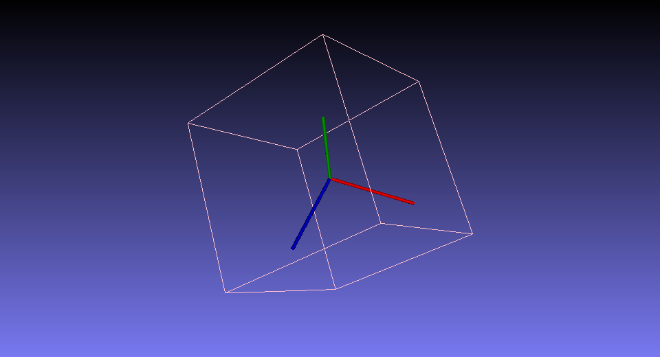
As we can see, drawing takes place through a call to the Viz3d :: showWidget () method with passing it the string name of the object, an instance of the created widget, and its position in the global coordinate system. A string name is necessary in order to be able to add, delete and update widgets in the 3D scene by name. If a widget with the same name is already present, it is deleted and replaced with a new one.
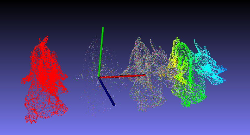
In addition to the cube and line, Viz implements a sphere, cylinder, plane, 2D circle, pictures and text in 3D and 2D, various types of trajectories, camera positions, and, of course, point clouds and a widget for working with a mesh (colorwise, painted or textured). This set of widgets is not final, and will be expanded. Moreover, it is possible to create custom views, but about this some other time. If you are interested in this opportunity, read this tutorial. And now let's consider another example of how to draw point clouds:
// . CV_32FC3 cv::Mat cloud = cv::viz::readCloud(“dragon.ply”); // cv::Mat colors(cloud.size(), CV_8UC3); theRNG().fill(colors, RNG::UNIFORM, 50, 255); // NAN - float qnan = std::numeric_limits<float>::quiet_NaN(); cv::Mat masked_cloud = cloud.clone(); for(int i = 0; i < cloud.total(); ++i) if ( i % 16 != 0) masked_cloud.at<Vec3f>(i) = Vec3f(qnan, qnan, qnan); Viz3d viz(“dragons”); viz.showWidget(“coo”, WCoordinateSystem()); // viz.showWidget(“red”, WCloud(cloud, Color::red()), Affine3d().translate(Vec3d(-1.0, 0.0, 0.0))); // viz.showWidget(“colored”, WCloud(cloud, colors), Affine3d().translate(Vec3d(+1.0, 0.0, 0.0))); // viz.showWidget(“masked”, WCloud(masked_cloud, colors), Affine3d::Identity()); // A , viz.showWidget(“painted”, WPaintedCloud(cloud), Affine3d().translate(Vec3d(+2.0, 0.0, 0.0))); viz.spin(); The result of this code is:
For more information about the available widgets, read our documentation .
Dynamically changing scene
It is often not enough to simply display objects so that the user can view them, but rather need to provide some dynamics. Objects can move, change their attributes. If we have a video stream with Kinect, then you can play the so-called point cloud vide. To do this, you can do the following:
cv::VideoCapture capture(CV_CAP_OPENNI) Viz3d viz(“dynamic”); //... ... // viz.setViewerPose(Affine3d().translate(1.0, 0.0, 0.0)); while(!viz.wasStopped()) { //... ... // , // , Kinect // , capture.grab(); capture.retrieve(color, CV_CAP_OPENNI_BGR_IMAGE); capture.retrieve(depth, CV_CAP_OPENNI_DEPTH_MAP); Mat cloud = computeCloud(depth); Mat display = normalizeDepth(depth); viz.showWidget("cloud", WCloud(cloud, color)); viz.showWidget("image", WImageOverlay(display, Rect(0, 0, 240, 160))); // 30 viz.spinOnce(30 /*ms*/, true /*force_redraw*/)); } This loop will run until the user closes the window. At the same time, at each iteration of the cycle, the widget with the old cloud will be replaced with a new one with a new cloud.
Management interface
At the moment, the camera control is done in the so-called trackball camera style, convenient for viewing various 3D objects. Imagine that in front of the camera there is a certain point in 3D, around which this camera rotates with the mouse. The scroller on the mouse brings / removes to and from this point. Using the shift / ctrl buttons and mouse, you can move this point of rotation in the 3D world. In the future, it is planned to implement a free-fly mode for navigating large spaces. I also recommend pressing the hotkey 'H' while Viz is running, to read the information printed on the console about other hotkeys and features, from saving screenshots to turning on anaglyph stereo.
How to build an OpenCV Viz module
And finally, for those who, after reading this text, had a burning desire to start using this module, this section is intended. Viz can be used on all three dominant PC platforms - Windows, Linux, and Mac. You will need to install VTK and compile OpenCV with VTK support. OpenCV itself with the Viz module can only be downloaded from our repository on GitHub https://github.com/Itseez/opencv in the 2.4 and master branches. So, the instruction:
1. Installing VTK
Under Linux, the easiest solution is to install VTK from the apt repository via the apt-get install command libvtk5-dev. Under Windows, you need to download VTK from the developer’s site, the best is version 5.10, generate a CMake project for Visual Studio and compile it in the Release and Debug configurations. I recommend unchecking CMake BUILD_SHARED_LIBS, which will lead to compilation of VTK static libraries. In this case, after compilation, the size of the OpenCV Viz module without any dependencies will be only about 10 MB.
Under Mac, for OSX 10.8 and earlier, any version of VTK will work; under 10.9, Mavericks will be able to compile VTK 6.2 from the official github.com/Kitware/VTK.git repository. There were no 6.2 releases at the time of writing this blogpost. Under Mac, it is also recommended to generate a project under Xcode using CMake and build static libraries in the Release and Debug configurations.
2. Compiling OpenCV with VTK
This step is easier and faster. I give commands for Linux, under Windows everything is not much different
- git clone github.com/Itseez/opencv.git
- [optional] git checkout -b 2.4 origin / 2.4
- mkdir build && cd build
- cmake -DWITH_VTK = ON -DVTK_DIR = <path to VTK build directory> ../opencv
If you put VTK through apt-get install, then you do not need to specify the path to it - it will be found by CMake automatically. Next, you need to make sure in the CMake console log that he found and connected VTK. And did not report any incompatibilities. For example, if you compile OpenCV with Qt5 support, and VTK is compiled with Qt4, linking with VTK will cause the application to crash at the initialization stage before entering the main () function. The solution is to choose one thing. Or compile VTK without Qt4 by unchecking the corresponding checkbox in CMake for VTK. Either take VTK 6.1 or higher and build it with Qt5 support. Finally, to build OpenCV, run make -j 6
3. Launch of texts (optional)
I also recommend downloading this repository: github.com/Itseez/opencv_extra.git , set the path to opencv_extra / testdata in the environment variable OPENCV_TEST_DATA_PATH. And run the opencv_test_viz file from the build directory of the OpenCV. On this application, you can familiarize yourself with all the current features of this module, and its source can be used to learn the API.
Conclusion
Well, so I got to the conclusion. I hope it was interesting. With this post, I wanted to show what the main trend, from my point of view, is now observed in computer vision, and that the OpenCV library is moving with the times. And that in OpenCV there will appear algorithms for working with the 3D world. Because we ourselves will develop them either with the help of Google Summer of Code students, or grateful users using our base, will participate in the creation and development of similar algorithms in OpenCV.
I also wanted to interest you with this developed tool, or maybe even this area for research. By the way, if you have a desire to conduct a similar development for OpenCV - You are welcome! We accept pull requests via GitHub. Instructions posted here . We will be glad to see a new well-working approach :-)
And although the main base is now created, I think in the future new features will be added to Viz. For example, a model of the skeleton of the human hand and its visualization. Or 3D world maps from algorithms like PTAM. Or maybe a network client so that it is possible to send data for visualization from a mobile device when debugging algorithms on it :) But these are insane ideas so far :-). If interested, in the next blog post I could talk about some algorithm, for example, ICP or Kinect Fusion, and how Viz was used to debug and visualize it.
And for those who read to the end - a bonus. Here is my optimized and lightweight remake of my own Kinect Fusion implementation in the PCL library.
Source: https://habr.com/ru/post/217021/
All Articles