We start to study Cortex-M on the example of STM32
This article is the first in the planned cycle of articles on the study of programming microcontrollers. Studying various materials, I noted that almost all of them begin with the fact that the beginner is invited to download (or use the library with the development environment) to work with peripheral devices and use it to write their first program (usually blinking LED).
I was very surprised. If you believe these articles, for programming it is not necessary even to read the documentation for the programmable controller. I was taught the tricks of “iron programming” in a completely different way.
In this article, the path from the phrase “Yes, I want to try!” To a joyful wink of a LED, will be much longer than that of other authors. I will try to reveal the aspects of microcontroller programming that hide behind the use of library functions and ready-made examples.
If you intend to seriously study the programming of microcontrollers, this article is for you. Perhaps it may interest those who have played enough with the Arduino and want to get their hands on all the hardware capabilities of iron.
Many may say that it’s better to start learning microcontrollers with AVR, PIC, 8051 or something else. The issue is multifaceted and controversial. I know enough examples when people studied Cortex-M, programmed AVR, ARM7, etc. I myself began with the Cortex-M3. If you are faced with a specific task, there is a lot of information on the Internet comparing various types of microcontrollers and the problems solved with their help. On Habré, this question was also raised, for example, here .
')
We assume that we figured out the type of microcontroller. But the market presents a huge range of different modifications from different manufacturers. They differ in many parameters - from the size of flash memory to the number of analog inputs. For each task, the choice should be made individually. There are no general recommendations and there can not be. I will only note that it is worth starting a study with MC manufacturers having as large a range as possible. Then, when choosing an MC for a specific task, there is a great enough chance that from the presented assortment something will suit you.
I chose STM32 (although I think it is better to start studying with MK from Texas Instruments - the documentation is very well written), because they are widespread among Russian electronics developers. If you have problems and questions, you can easily find solutions on the forums. Another advantage is a rich selection of demo boards from both the manufacturer and third-party organizations.
Unfortunately, to start programming MK is not enough just one PC. We'll have to get a demo board and programmer somewhere.Although this reduces competition in the labor market.
I myself use the STM3220G-EVAL demo board and the J-Link PRO programmer. But for a start, it will be quite enough STM32F4DISCOVERY , which can be bought without any problems for a small amount.
All examples will be exactly for the STM32F4DISCOVERY debug board. At this stage, it will not matter to us that this motherboard is based on the MK Cortex-M4 core. In the near future, we will not use its features and advantages over the Cortex-M3. And what will happen next - we'll see.
If you have any other motherboard based on STM32F2xx / STM32F4xx, you can work with it. In the presentation of the material, I will try to describe in as much detail as possible why we are doing this way and not otherwise. I hope no one will have problems with the transfer of examples to another iron.
As already mentioned several times, for ARM microcontrollers there are a sufficient number of development environments, both paid and not so. And again I want to omit the controversy about this. I am using IAR Embedded Workbench for ARM 6.60 . All examples will be in this environment. If you like (or is used in your organization) something else (Keil, Eclipse, CCS, CooCoc, etc.) then this also does not hurt you much. On the features associated with the development environment, I will pay special attention.
I will not describe the installation process.
First, create an empty project. IAR allows you to create projects on ASM, C and C ++. We will use C.
An empty project with a main file will appear in front of us.
Now you need to configure the project to start working with "our" MK and debugger. The STM32F4DISCOVERY is installed on the MK STM32F407VG . It must be selected in the project properties (General Options-> Target-> Device):
When a target programmable processor is selected, its description is loaded, which provides ample opportunities for debugging (this will be discussed below). In addition, a configuration file is automatically attached with a description of the available address space for the linker. If necessary, we will touch on the topic of the linker configuration file in the following articles.
After that, you need to configure the debugger. Debugging of the program takes place directly "in the gland". This is done using the JTAG debugger. You can learn more about how this happens on Wikipedia . The ST-LINK / V2 debugger is integrated into the STM32F4DISCOVERY board. To work with a debugger, it is necessary to select its driver in the menu Debugger-> Setup-> Driver . It is also necessary to indicate that debugging should be done directly in the hardware. To do this, check the Debugger-> Download-> Use flash loader (s) flag
Now the project is ready for work (programming, pouring and debugging).
Let's summarize the intermediate result: the MC and the debug board are selected, the project is prepared. It's time to decide on the task.
We will not move away from the classics. The first project will be a flashing LED. Fortunately there are plenty of them on the board. What does this mean in terms of programming? First of all, it is necessary to study the schematic diagram of the demo board and understand how the LED “starts”.
User manual is available on the manufacturer's website. In this description there is even a separate section on the LEDs on the board - 4.4 LEDs . For example, we will use User LD3 . Find it on the scheme:
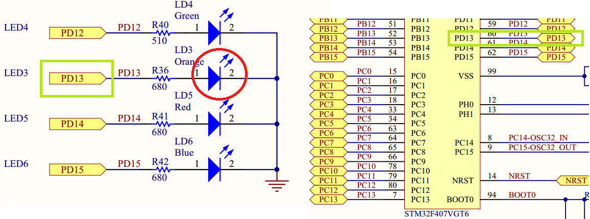
The simplest analysis of the circuit suggests that in order to “light up” the LED it is necessary to submit a “1” to the MK pin (which for a given MK corresponds to 3.3V). Off is made by applying to this pin "0". In the diagram, this pin is designated PD13 (this is probably the most important information from this document).
As a result, we can write "TZ" for our first program:
The program for MK should transfer the pin state of the MK PD13 from the state “0” to the state “1” and back with a certain periodicity visible to the human eye (an important note if you blink the LED too often the eye can not distinguish it).
Before proceeding with the implementation of our TK, it is necessary to understand how MK is managed.
To begin with, any MK includes the core, memory, and peripheral blocks. I think that everything is clear with memory. I will only mention, in STM32 there is a flash memory in which the MK program is stored (in general, this is not a true statement, the program can be stored in external non-volatile memory, but for now we’ll omit it) and other data, including user data. There is also SRAM - RAM.
The kernel is the part of the microcontroller that executes one command flow. In our MK core type - Cortex-M4. Kernel MK can be compared with the processor in the PC. It can only execute commands and transfer data to other units (this comparison does not take into account processors with integrated graphics accelerators).
In this case, the manufacturer MK does not develop the kernel. The core is purchased from ARM Limited . The main difference between different MK - in the periphery.
Peripheral blocks are blocks that interact with the "outside world" or perform specific functions that are inaccessible to the MC kernel. Modern MK (including STM32) contain a huge range of peripheral blocks. Peripheral units are designed to solve various tasks, from reading the voltage value from the analog input of the MC to data transmission to external devices via the SPI bus.
Unlike the MK core, the peripheral units do not follow the instructions. They only execute kernel commands. In this case, the participation of the kernel when executing a command is not required.
The interaction of the MK core with the peripheral unit is carried out with the help of special registers (there is still interaction through the interrupt mechanism and DMA, but more on that in the following posts). From the point of view of the kernel, this is simply a chunk of memory with a specific address, only this is not true . Writing data to a special register is equivalent to transmitting a command or data to a peripheral block. Read - receive data from a block or read its state. The description of peripheral blocks and their special registers takes the lion's share of the MC description.
IMPORTANT: After writing data to a special register and subsequent reading, you can get completely different data. For example, data transfer to a UART block for sending, and reading data received by a block from an external device, is performed using the same register.
Special registers are usually divided into bit fields. One (or several) bits control a specific parameter of the peripheral block, usually independently. For example, different bits of the same register control the state of different outputs of the MC.
If you are a C language guru, feel free to skip this section. It is intended primarily for those who have been taught (or who learned himself) to program for the PC. Experience shows that people often do not remember important teams. Here I will briefly remind you about bitwise operations and work directly with memory at its address.
Data recording by address in memory
Suppose that reading the description of the peripheral unit, we realized that for its correct operation it is necessary to write the number 0x3B into it. Special register address 0x60004012. The register is 32-bit.
If you do not immediately know how to do this, I will try to describe the chain of reasoning to get the right command.
The value 0x60004012 is nothing but the value of the pointer to the memory cell. It is necessary to indicate this in our program, ie, to do type conversion according to the syntax of the C language:
Thus, we have a pointer to an element. Now we need to write the required value to this element. This is done by dereferencing the pointer. Thus we get the right command:
Setting arbitrary bits to 1
Suppose that you need to set "1" to 7 and 1 bits at 0x60004012, while not changing the value of all other bits in the register. To do this, you must use a binary operation |. Immediately give the correct answer:
Pay attention to 2 facts. Bits are counted from zero, not from the first. This operation actually takes not less than 3 clocks - reading a value, modifying, writing. Sometimes this is not permissible, since between reading and writing the value of one of the bits that we are forbidden to change could be changed by the peripheral block. Do not forget about this feature, otherwise bugs can get, which are extremely difficult to catch.
Setting arbitrary bits to 0
Suppose you need to set “0” to 7 and 1 bits at 0x60004012, while not changing the value of all the other bits in the register. To do this, you must use the binary operation &. Immediately give the correct answer:
Or its simpler writing (don't worry about the extra operation, the compiler will calculate everything in advance even with minimal optimization):
Here I will try to describe some features of the programs for the MC, which is important to remember. Things are pretty obvious, but still.
The program has no end
In difference from the majority of programs for the PC, the program for MK should not end, NEVER! And what exactly MK should do after the completion of your program? The question is practically rhetorical. Therefore, do not forget to make sure that you do not forget the eternal cycle. If desired, you can put the MK in sleep mode.
Use integer variables
Despite the fact that we use the MK with the core Cortex-M4, which hardware performs operations on floating-point numbers, I advise you to abandon their use. In MK without the support of such operations, the computation time will be simply huge.
Avoid dynamic memory allocation
This is just a tip. The reason is simple - there is little memory. I have repeatedly met with libraries in which there were “slow leaks” of memory. It was very unpleasant when, after several weeks of stable operation, the MK hung up with an error. It is better to think in advance about the architecture of your program so that you don’t have to use dynamic memory allocation.
If you still want to use - carefully study the work of the memory manager or write your own.
Work on the program for MK always begins with reading the documentation. For our MK Reference manual is available on the manufacturer's website. There are many pages, but you don’t need to read everything yet . As already mentioned, most of the documentation is a description of the peripheral blocks and their registers. I also want to draw attention to the fact that this Reference Manual was written not for one MK, but for several lines. This suggests that the code will be portable when switching to other MCs in these lines (unless of course you try to use peripheral blocks that are not in the used MC).
First of all, you need to decide which blocks to work with. For this, it is enough to study the sections of the Introduction and Main features .
Direct control of the state of the MK pins is performed using a GPIO block. As stated in the documentation in the MK STM32 there can be up to 11 independent GPIO blocks. Various GPIO peripheral blocks are called ports. Ports are designated by letters from A to K. Each port can contain up to 16 pins. As we noted earlier, the LED is connected to the PD13 pin. This means that this pin is controlled by the GPIO peripheral block port D. Pin number is 13.
No other peripheral blocks are needed this time.
To reduce the power consumption of the MK, almost all peripheral blocks are switched off after turning on the MK. Switching on / off the block is performed by applying / stopping the clock signal to its input. For correct operation, it is necessary to configure the MK clock signal controller so that a clock signal is supplied to the necessary peripheral unit.
Important: The peripheral unit cannot start operation immediately after the clock signal is turned on. It is necessary to wait several cycles until it “starts”. People who use libraries for peripherals often don’t even know about this feature.
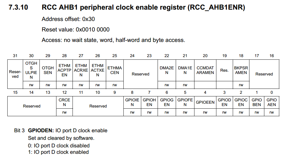
Registers RCC XXX peripheral clock enable register are responsible for turning on the clocking of peripheral blocks. AHB1, AHB2, AHB3, APB1 and APB2 buses can stand in the place of XXX. After a careful study of the description of the relevant registers, it can be concluded that the clocking of the GPIOD peripheral unit is enabled by setting “1” to the third bit of the RCC AHB1 peripheral clock enable register register (RCC_AHB1ENR) :
Now you need to figure out how to find out the address of the register RCC_AHB1ENR .
Note: The description of the system clocking MK STM32 worthy of a separate article. If readers have a desire, I will cover this section in more detail in one of the following articles.
Determination of addresses of special registers should be started from reading the section Memory map in Reference manual. You may notice that each block is allocated its own part of the address space. For example, for an RCC block, this section is 0x4002 3800 - 0x4002 3BFF:
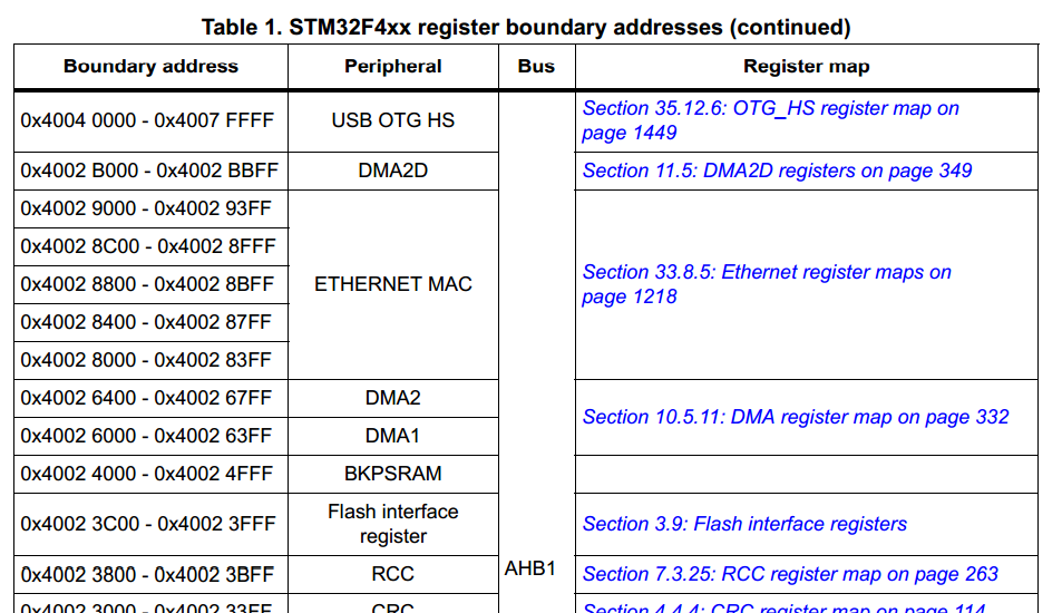
Following the link to the Register map of the RCC block we find the line with the register RCC_AHB1ENR of interest to us:
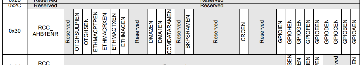
To get the address of the register, you must add Addr to the initial value of the address space of the RCC block . offset of the desired register. Addres offset is also indicated in the register description (see screenshot above).
As a result, we determined the address of the register RCC_AHB1ENR - 0x4002 3830.
For general acquaintance with the GPIO unit, I strongly recommend to fully read the relevant section of the Reference Manual. While you can not really pay attention to the Alternate mode . This will be left for later.
Now our task is to learn how to manage the state of the pin MK. Let's go straight to the description of the GPIO registers.
First of all, it is necessary to set the operation mode of pin 13 of port D as General purpose output mode , which means that the GPIO block will control the state of pin MK. The mode of operation of the MK pins is controlled by the register GPIO port mode register (GPIOx_MODER) (x = A..I / J / K) :
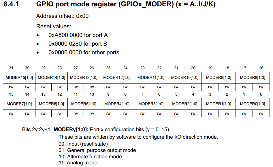
As can be seen from the description, in order to make the required settings, we need to write the value 01b to 26-27 bits of the GPIOx_MODER register. Address register can be determined by the same method as described above.
The GPIO block allows you to apply additional settings for the output pin ports. These settings are made in the registers:
We will not change these parameters, since we are quite satisfied with the default values.
Finally, we come to the moment of controlling the state of the output of the MC. There are two methods for setting the output value on a certain MK pin.
Use the register GPIO port bit set / reset register (GPIOx_BSRR)
Writing “0” or “1” in bits 0-16 results in a corresponding change in the state of the port pins. In order to set a certain value at the output of one or several pins of the MK and not change the states of the others, it will be necessary to use the operation of modifying individual bits. Such an operation is performed at least 3 cycles. If it is necessary to record 1 in part of bits, and in other 0, then at least 4 cycles will be needed. This method is preferable to use to change the state of output to the opposite, if its initial state is not known.
GPIO port bit set / reset register (GPIOx_BSRR)

Unlike the previous method, writing 0 to any of the bits in this register does not lead to anything (and indeed, all the bits are write-only!). Writing 1 to bits 0-15 will result in setting “1” at the corresponding MK output. Writing 1 to bits 16-31 will result in setting “0” at the corresponding output of the MC. This method is preferable to the previous one if it is necessary to set a certain value on the “MK” pin, and not to change it.
Finding the addresses of all the necessary registers, you can write a program that includes the LED:
You can compile ( Project-> Compile ) and upload ( Project-> Download-> Download active application ). Or, start debugging ( Project-> Dpwnload and Debug ) and start execution (F5).
The LED is on fire!
The flashing of the LED is nothing but alternate on and off with a delay between these actions. The easiest way is to put the on and off in an eternal cycle, and insert a delay between them.
The value of 1,000,000 in the delay was chosen experimentally so that the blinking period of the LED could be distinguished by the eye, but it would not be too long either.
The disadvantage of the chosen approach by the blinking LED is that the MK core spends most of the time in empty cycles, although it could do something useful (in our example, there are no other tasks, but in the future they will appear).
In order to avoid this, a loop counter is usually used, and the state of the pin MK is switched when a certain number of cycles pass through the program.
But even here it will not be without problems, with a change in the number of commands executed within the cycle, the period of blinking by the LED will change (or the period of execution of other commands in the cycle). But at this stage we cannot fight it.
IAR allows you to debug an application directly in the gland. Everything looks almost the same as debugging a PC application. There is a step-by-step mode, entering a function, viewing the value of variables (In debug mode, View-> Watch-> Watch1 / 4 ).
But besides this, there is the possibility of viewing the values of the core registers, special registers of peripheral blocks (View-> Register), etc.
I strongly recommend that you familiarize yourself with the debugger features while learning the MK programming.
Probably, many will say that it’s not correct to manually enter addresses into the program, since the manufacturer provides files with definitions of registers and bit fields, libraries for working with peripherals, and other tools that make life easier for the developer. I completely agree with this, but I still think that the first steps in programming MK should be done by digging up the documentation for manually, independently determining the necessary registers and bit fields. In the future, this can not be used, but you need to be able to necessarily.
I will give just a few reasons for this statement:
Thanks to everyone who read my post, it turned out much more than I expected at the beginning.
Waiting for your comments and reasoned criticism. If the reader has a desire, I will try to continue the cycle of articles. Maybe someone has ideas about topics that would be worth highlighting - I would be glad to hear them.
I was very surprised. If you believe these articles, for programming it is not necessary even to read the documentation for the programmable controller. I was taught the tricks of “iron programming” in a completely different way.
In this article, the path from the phrase “Yes, I want to try!” To a joyful wink of a LED, will be much longer than that of other authors. I will try to reveal the aspects of microcontroller programming that hide behind the use of library functions and ready-made examples.
If you intend to seriously study the programming of microcontrollers, this article is for you. Perhaps it may interest those who have played enough with the Arduino and want to get their hands on all the hardware capabilities of iron.
Microcontroller selection
Many may say that it’s better to start learning microcontrollers with AVR, PIC, 8051 or something else. The issue is multifaceted and controversial. I know enough examples when people studied Cortex-M, programmed AVR, ARM7, etc. I myself began with the Cortex-M3. If you are faced with a specific task, there is a lot of information on the Internet comparing various types of microcontrollers and the problems solved with their help. On Habré, this question was also raised, for example, here .
')
We assume that we figured out the type of microcontroller. But the market presents a huge range of different modifications from different manufacturers. They differ in many parameters - from the size of flash memory to the number of analog inputs. For each task, the choice should be made individually. There are no general recommendations and there can not be. I will only note that it is worth starting a study with MC manufacturers having as large a range as possible. Then, when choosing an MC for a specific task, there is a great enough chance that from the presented assortment something will suit you.
I chose STM32 (although I think it is better to start studying with MK from Texas Instruments - the documentation is very well written), because they are widespread among Russian electronics developers. If you have problems and questions, you can easily find solutions on the forums. Another advantage is a rich selection of demo boards from both the manufacturer and third-party organizations.
What is needed to learn?
Unfortunately, to start programming MK is not enough just one PC. We'll have to get a demo board and programmer somewhere.
I myself use the STM3220G-EVAL demo board and the J-Link PRO programmer. But for a start, it will be quite enough STM32F4DISCOVERY , which can be bought without any problems for a small amount.
All examples will be exactly for the STM32F4DISCOVERY debug board. At this stage, it will not matter to us that this motherboard is based on the MK Cortex-M4 core. In the near future, we will not use its features and advantages over the Cortex-M3. And what will happen next - we'll see.
If you have any other motherboard based on STM32F2xx / STM32F4xx, you can work with it. In the presentation of the material, I will try to describe in as much detail as possible why we are doing this way and not otherwise. I hope no one will have problems with the transfer of examples to another iron.
Development environment
As already mentioned several times, for ARM microcontrollers there are a sufficient number of development environments, both paid and not so. And again I want to omit the controversy about this. I am using IAR Embedded Workbench for ARM 6.60 . All examples will be in this environment. If you like (or is used in your organization) something else (Keil, Eclipse, CCS, CooCoc, etc.) then this also does not hurt you much. On the features associated with the development environment, I will pay special attention.
Why a paid development environment?
Maybe someone will not be quite happy with the fact that I propose to use a paid development environment, but in IAR there is an opportunity to get a temporary license without functional limit, or an unlimited license with restriction on code size (32KB for MK is a lot).
In addition, I immediately note that for some of the MK there are no free development environments. And unfortunately, these MC in some areas are irreplaceable.
In addition, I immediately note that for some of the MK there are no free development environments. And unfortunately, these MC in some areas are irreplaceable.
I will not describe the installation process.
Where to begin?
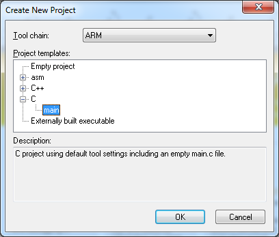
Project creation
First, create an empty project. IAR allows you to create projects on ASM, C and C ++. We will use C.
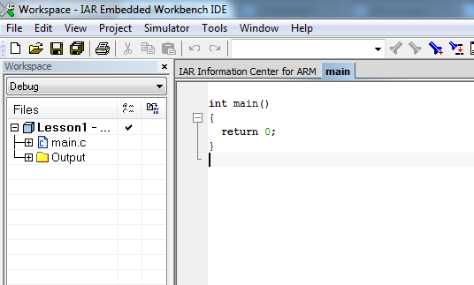
An empty project with a main file will appear in front of us.
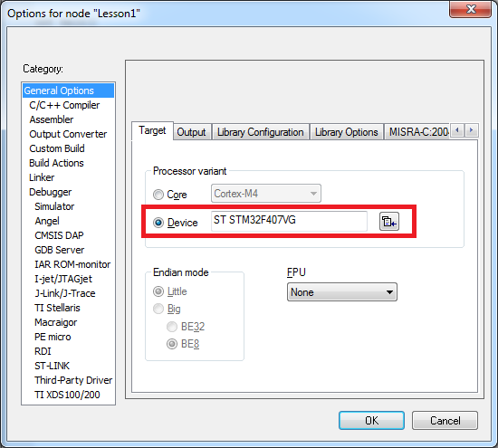
Now you need to configure the project to start working with "our" MK and debugger. The STM32F4DISCOVERY is installed on the MK STM32F407VG . It must be selected in the project properties (General Options-> Target-> Device):
When a target programmable processor is selected, its description is loaded, which provides ample opportunities for debugging (this will be discussed below). In addition, a configuration file is automatically attached with a description of the available address space for the linker. If necessary, we will touch on the topic of the linker configuration file in the following articles.
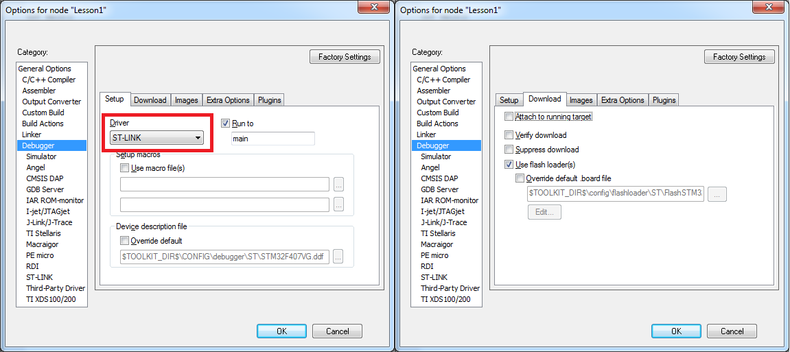
After that, you need to configure the debugger. Debugging of the program takes place directly "in the gland". This is done using the JTAG debugger. You can learn more about how this happens on Wikipedia . The ST-LINK / V2 debugger is integrated into the STM32F4DISCOVERY board. To work with a debugger, it is necessary to select its driver in the menu Debugger-> Setup-> Driver . It is also necessary to indicate that debugging should be done directly in the hardware. To do this, check the Debugger-> Download-> Use flash loader (s) flag
For those who saw the word Simulator
Theoretically, IAR allows you to debug programs using a simulator. But I have never met him in practice.
Now the project is ready for work (programming, pouring and debugging).
"TZ" for the first project
Let's summarize the intermediate result: the MC and the debug board are selected, the project is prepared. It's time to decide on the task.
We will not move away from the classics. The first project will be a flashing LED. Fortunately there are plenty of them on the board. What does this mean in terms of programming? First of all, it is necessary to study the schematic diagram of the demo board and understand how the LED “starts”.
User manual is available on the manufacturer's website. In this description there is even a separate section on the LEDs on the board - 4.4 LEDs . For example, we will use User LD3 . Find it on the scheme:
The simplest analysis of the circuit suggests that in order to “light up” the LED it is necessary to submit a “1” to the MK pin (which for a given MK corresponds to 3.3V). Off is made by applying to this pin "0". In the diagram, this pin is designated PD13 (this is probably the most important information from this document).
As a result, we can write "TZ" for our first program:
The program for MK should transfer the pin state of the MK PD13 from the state “0” to the state “1” and back with a certain periodicity visible to the human eye (an important note if you blink the LED too often the eye can not distinguish it).
Before you start programming, or a little theory
Before proceeding with the implementation of our TK, it is necessary to understand how MK is managed.
To begin with, any MK includes the core, memory, and peripheral blocks. I think that everything is clear with memory. I will only mention, in STM32 there is a flash memory in which the MK program is stored (in general, this is not a true statement, the program can be stored in external non-volatile memory, but for now we’ll omit it) and other data, including user data. There is also SRAM - RAM.
The kernel is the part of the microcontroller that executes one command flow. In our MK core type - Cortex-M4. Kernel MK can be compared with the processor in the PC. It can only execute commands and transfer data to other units (this comparison does not take into account processors with integrated graphics accelerators).
In this case, the manufacturer MK does not develop the kernel. The core is purchased from ARM Limited . The main difference between different MK - in the periphery.
Peripheral blocks are blocks that interact with the "outside world" or perform specific functions that are inaccessible to the MC kernel. Modern MK (including STM32) contain a huge range of peripheral blocks. Peripheral units are designed to solve various tasks, from reading the voltage value from the analog input of the MC to data transmission to external devices via the SPI bus.
Unlike the MK core, the peripheral units do not follow the instructions. They only execute kernel commands. In this case, the participation of the kernel when executing a command is not required.
Example
As an example, you can take the UART block, which is designed to receive and transmit data from the MC to external devices. From the core, it is only necessary to configure the block and give it the data for transmission. After that, the kernel can continue to follow the instructions. On the shoulders of the peripheral unit, the management of the corresponding output of the MC for data transmission in accordance with the protocol rests. The peripheral unit itself translates the output of the MK to the required state "0" or "1" at the right time, making the transfer.
The interaction of the core with the peripheral unit
The interaction of the MK core with the peripheral unit is carried out with the help of special registers (there is still interaction through the interrupt mechanism and DMA, but more on that in the following posts). From the point of view of the kernel, this is simply a chunk of memory with a specific address, only this is not true . Writing data to a special register is equivalent to transmitting a command or data to a peripheral block. Read - receive data from a block or read its state. The description of peripheral blocks and their special registers takes the lion's share of the MC description.
IMPORTANT: After writing data to a special register and subsequent reading, you can get completely different data. For example, data transfer to a UART block for sending, and reading data received by a block from an external device, is performed using the same register.
Special registers are usually divided into bit fields. One (or several) bits control a specific parameter of the peripheral block, usually independently. For example, different bits of the same register control the state of different outputs of the MC.
Remembering C
If you are a C language guru, feel free to skip this section. It is intended primarily for those who have been taught (or who learned himself) to program for the PC. Experience shows that people often do not remember important teams. Here I will briefly remind you about bitwise operations and work directly with memory at its address.
Data recording by address in memory
Suppose that reading the description of the peripheral unit, we realized that for its correct operation it is necessary to write the number 0x3B into it. Special register address 0x60004012. The register is 32-bit.
If you do not immediately know how to do this, I will try to describe the chain of reasoning to get the right command.
The value 0x60004012 is nothing but the value of the pointer to the memory cell. It is necessary to indicate this in our program, ie, to do type conversion according to the syntax of the C language:
(unsigned long*)(0x60004012) Thus, we have a pointer to an element. Now we need to write the required value to this element. This is done by dereferencing the pointer. Thus we get the right command:
*(unsigned long*)(0x60004012) = 0x3B; Setting arbitrary bits to 1
Suppose that you need to set "1" to 7 and 1 bits at 0x60004012, while not changing the value of all other bits in the register. To do this, you must use a binary operation |. Immediately give the correct answer:
*(unsigned long*)(0x60004012) |= 0x82; Pay attention to 2 facts. Bits are counted from zero, not from the first. This operation actually takes not less than 3 clocks - reading a value, modifying, writing. Sometimes this is not permissible, since between reading and writing the value of one of the bits that we are forbidden to change could be changed by the peripheral block. Do not forget about this feature, otherwise bugs can get, which are extremely difficult to catch.
Setting arbitrary bits to 0
Suppose you need to set “0” to 7 and 1 bits at 0x60004012, while not changing the value of all the other bits in the register. To do this, you must use the binary operation &. Immediately give the correct answer:
*(unsigned long*)(0x60004012) &= 0xFFFFFF7D; Or its simpler writing (don't worry about the extra operation, the compiler will calculate everything in advance even with minimal optimization):
*(unsigned long*)(0x60004012) &= (~0x82); Some features of programs for MK
Here I will try to describe some features of the programs for the MC, which is important to remember. Things are pretty obvious, but still.
The program has no end
In difference from the majority of programs for the PC, the program for MK should not end, NEVER! And what exactly MK should do after the completion of your program? The question is practically rhetorical. Therefore, do not forget to make sure that you do not forget the eternal cycle. If desired, you can put the MK in sleep mode.
Use integer variables
Despite the fact that we use the MK with the core Cortex-M4, which hardware performs operations on floating-point numbers, I advise you to abandon their use. In MK without the support of such operations, the computation time will be simply huge.
Avoid dynamic memory allocation
This is just a tip. The reason is simple - there is little memory. I have repeatedly met with libraries in which there were “slow leaks” of memory. It was very unpleasant when, after several weeks of stable operation, the MK hung up with an error. It is better to think in advance about the architecture of your program so that you don’t have to use dynamic memory allocation.
If you still want to use - carefully study the work of the memory manager or write your own.
Getting started!
Work on the program for MK always begins with reading the documentation. For our MK Reference manual is available on the manufacturer's website. There are many pages, but you don’t need to read everything yet . As already mentioned, most of the documentation is a description of the peripheral blocks and their registers. I also want to draw attention to the fact that this Reference Manual was written not for one MK, but for several lines. This suggests that the code will be portable when switching to other MCs in these lines (unless of course you try to use peripheral blocks that are not in the used MC).
First of all, you need to decide which blocks to work with. For this, it is enough to study the sections of the Introduction and Main features .
Direct control of the state of the MK pins is performed using a GPIO block. As stated in the documentation in the MK STM32 there can be up to 11 independent GPIO blocks. Various GPIO peripheral blocks are called ports. Ports are designated by letters from A to K. Each port can contain up to 16 pins. As we noted earlier, the LED is connected to the PD13 pin. This means that this pin is controlled by the GPIO peripheral block port D. Pin number is 13.
No other peripheral blocks are needed this time.
Control peripheral clocking
To reduce the power consumption of the MK, almost all peripheral blocks are switched off after turning on the MK. Switching on / off the block is performed by applying / stopping the clock signal to its input. For correct operation, it is necessary to configure the MK clock signal controller so that a clock signal is supplied to the necessary peripheral unit.
Important: The peripheral unit cannot start operation immediately after the clock signal is turned on. It is necessary to wait several cycles until it “starts”. People who use libraries for peripherals often don’t even know about this feature.
Registers RCC XXX peripheral clock enable register are responsible for turning on the clocking of peripheral blocks. AHB1, AHB2, AHB3, APB1 and APB2 buses can stand in the place of XXX. After a careful study of the description of the relevant registers, it can be concluded that the clocking of the GPIOD peripheral unit is enabled by setting “1” to the third bit of the RCC AHB1 peripheral clock enable register register (RCC_AHB1ENR) :
Now you need to figure out how to find out the address of the register RCC_AHB1ENR .
Note: The description of the system clocking MK STM32 worthy of a separate article. If readers have a desire, I will cover this section in more detail in one of the following articles.
Determination of special register addresses
Determination of addresses of special registers should be started from reading the section Memory map in Reference manual. You may notice that each block is allocated its own part of the address space. For example, for an RCC block, this section is 0x4002 3800 - 0x4002 3BFF:
Following the link to the Register map of the RCC block we find the line with the register RCC_AHB1ENR of interest to us:
To get the address of the register, you must add Addr to the initial value of the address space of the RCC block . offset of the desired register. Addres offset is also indicated in the register description (see screenshot above).
As a result, we determined the address of the register RCC_AHB1ENR - 0x4002 3830.
GPIO block
For general acquaintance with the GPIO unit, I strongly recommend to fully read the relevant section of the Reference Manual. While you can not really pay attention to the Alternate mode . This will be left for later.
Now our task is to learn how to manage the state of the pin MK. Let's go straight to the description of the GPIO registers.
Operation mode
First of all, it is necessary to set the operation mode of pin 13 of port D as General purpose output mode , which means that the GPIO block will control the state of pin MK. The mode of operation of the MK pins is controlled by the register GPIO port mode register (GPIOx_MODER) (x = A..I / J / K) :
As can be seen from the description, in order to make the required settings, we need to write the value 01b to 26-27 bits of the GPIOx_MODER register. Address register can be determined by the same method as described above.
Setting the parameters of the output pins of the GPIO port
The GPIO block allows you to apply additional settings for the output pin ports. These settings are made in the registers:
- GPIO port output type register (GPIOx_OTYPER) - set the type of output push-pull or open-drain
- GPIO port output speed register (GPIOx_OSPEEDR) - set the speed of the output
We will not change these parameters, since we are quite satisfied with the default values.
Setting the value on the pin MK
Finally, we come to the moment of controlling the state of the output of the MC. There are two methods for setting the output value on a certain MK pin.
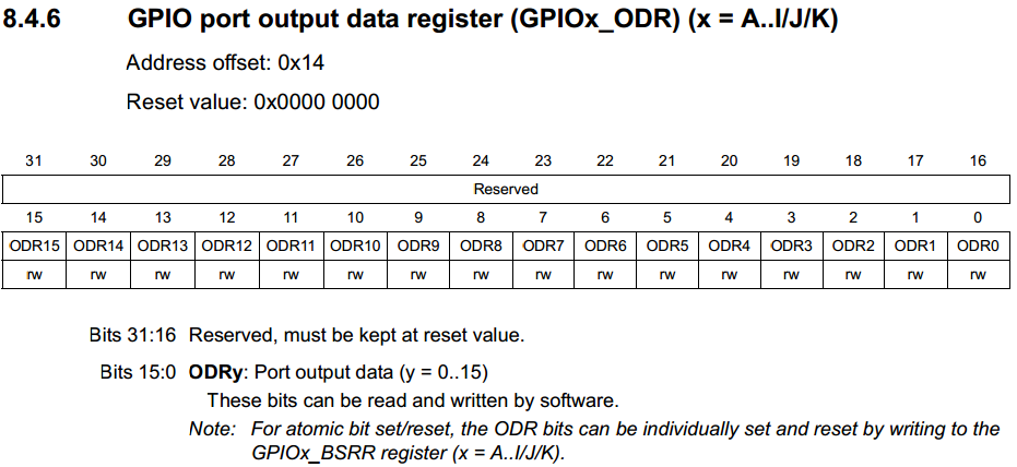
Use the register GPIO port bit set / reset register (GPIOx_BSRR)
Writing “0” or “1” in bits 0-16 results in a corresponding change in the state of the port pins. In order to set a certain value at the output of one or several pins of the MK and not change the states of the others, it will be necessary to use the operation of modifying individual bits. Such an operation is performed at least 3 cycles. If it is necessary to record 1 in part of bits, and in other 0, then at least 4 cycles will be needed. This method is preferable to use to change the state of output to the opposite, if its initial state is not known.
GPIO port bit set / reset register (GPIOx_BSRR)
Unlike the previous method, writing 0 to any of the bits in this register does not lead to anything (and indeed, all the bits are write-only!). Writing 1 to bits 0-15 will result in setting “1” at the corresponding MK output. Writing 1 to bits 16-31 will result in setting “0” at the corresponding output of the MC. This method is preferable to the previous one if it is necessary to set a certain value on the “MK” pin, and not to change it.
Light the LED!
Finding the addresses of all the necessary registers, you can write a program that includes the LED:
void main() { //Enable port D clocking *(unsigned long*)(0x40023830) |= 0x8; //little delay for GPIOD get ready volatile unsigned long i=0; i++; i++; i++; i=0; //Set PD13 as General purpose output *(unsigned long*)(0x40020C00) = (*(unsigned long*)(0x40020C00)& (~0x0C000000)) | (0x04000000); //Turn LED ON! *(unsigned long*)(0x40020C14) |= 0x2000; while(1); } You can compile ( Project-> Compile ) and upload ( Project-> Download-> Download active application ). Or, start debugging ( Project-> Dpwnload and Debug ) and start execution (F5).
The LED is on fire!
Blink LED
The flashing of the LED is nothing but alternate on and off with a delay between these actions. The easiest way is to put the on and off in an eternal cycle, and insert a delay between them.
void main() { //Enable port D clocking *(unsigned long*)(0x40023830) |= 0x8; //little delay for GPIOD get ready volatile unsigned long i=0; i++; i++; i++; i=0; //Set PD13 as General purpose output *(unsigned long*)(0x40020C00) = (*(unsigned long*)(0x40020C00)& (~0x0C000000)) | (0x04000000); while(1) { //Turn LED ON *(unsigned long*)(0x40020C14) |= 0x2000; //Delay for( i=0; i<1000000 ;++i ); //Turn LED OFF *(unsigned long*)(0x40020C14) &= ~0x2000; //Delay for( i=0; i<1000000 ;++i ); } } The value of 1,000,000 in the delay was chosen experimentally so that the blinking period of the LED could be distinguished by the eye, but it would not be too long either.
We optimize the algorithm
The disadvantage of the chosen approach by the blinking LED is that the MK core spends most of the time in empty cycles, although it could do something useful (in our example, there are no other tasks, but in the future they will appear).
In order to avoid this, a loop counter is usually used, and the state of the pin MK is switched when a certain number of cycles pass through the program.
void main() { //Enable port D clocking *(unsigned long*)(0x40023830) |= 0x8; //little delay for GPIOD get ready volatile unsigned long i=0; i++; i++; i++; i=0; //Set PD13 as General purpose output *(unsigned long*)(0x40020C00) = (*(unsigned long*)(0x40020C00)& (~0x0C000000)) | (0x04000000); while(1) { i++; if( !(i%2000000) ) { //Turn LED ON *(unsigned long*)(0x4002014) |= 0x2020; } else if( !(i%1000000) ) { //Turn LED OFF *(unsigned long*)(0x4002014) &= ~0x2000; } } } But even here it will not be without problems, with a change in the number of commands executed within the cycle, the period of blinking by the LED will change (or the period of execution of other commands in the cycle). But at this stage we cannot fight it.
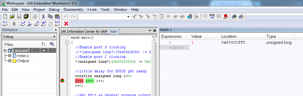
Something about debugging
IAR allows you to debug an application directly in the gland. Everything looks almost the same as debugging a PC application. There is a step-by-step mode, entering a function, viewing the value of variables (In debug mode, View-> Watch-> Watch1 / 4 ).

But besides this, there is the possibility of viewing the values of the core registers, special registers of peripheral blocks (View-> Register), etc.
I strongly recommend that you familiarize yourself with the debugger features while learning the MK programming.
A few words in conclusion
Probably, many will say that it’s not correct to manually enter addresses into the program, since the manufacturer provides files with definitions of registers and bit fields, libraries for working with peripherals, and other tools that make life easier for the developer. I completely agree with this, but I still think that the first steps in programming MK should be done by digging up the documentation for manually, independently determining the necessary registers and bit fields. In the future, this can not be used, but you need to be able to necessarily.
I will give just a few reasons for this statement:
- Sometimes there are errors in libraries from the manufacturer! Once I almost ripped off the project due to this. I re-soldered the chip several times, thinking a hundred had damaged the crystal during soldering (before this happened). And the problem was that the address of the special register was incorrectly registered in the library. Usually this happens with MK or MK lines only to those who have entered the market.
- Libraries for the operation of some manufacturers of the periphery do not realize all the capabilities of peripheral units. This is especially the sin of Luminary Micro , which was later bought out by TI. I had to write the initialization of the periphery manually.
- Many get used to start programming MK with the study of examples. I believe that first it is necessary to determine the fact that allows you to implement MK. This can only be understood by reading the documentation.If something is not in the examples, this does not mean that iron does not support it. The latest example is hardware support for PTP STM32. Of course, you can find something online, but this is not included in the standard set from the manufacturer
- The drivers of peripheral blocks of some manufacturers are not so optimized that up to 20 clocks are spent on switching the state of a pin by means of the library. This is a luxury for some tasks.
Thanks to everyone who read my post, it turned out much more than I expected at the beginning.
Waiting for your comments and reasoned criticism. If the reader has a desire, I will try to continue the cycle of articles. Maybe someone has ideas about topics that would be worth highlighting - I would be glad to hear them.
Source: https://habr.com/ru/post/216843/
All Articles