Where "soap" in WPF comes from and how to deal with it
This guide is for WPF developers looking to get the most out of the picture in their applications. Graphic system WPF to the bone is vector, but the end result of its work is still a raster. If you do not pay due attention to this fact, you can encounter various sorts of "soap" - parasitic artifacts of rasterization. In such a situation, it is important not to lose the presence of mind, the reasons for their occurrence are quite rational, and the methods of control are fairly simple and effective.
Table of contents
Introduction
1. Scaling bitmaps
2. Coordinates not multiples of pixel size.
3. Native resolution of raster images
4. Rasterization of vector images
5. Moving text vertically
6. Using the SnapsToDevicePixels property
7. Independent drawing of controls
Conclusion
Links
Introduction
The cunning of rasterization artifacts is that they do not catch the eye. Many developers simply do not notice defects of a size of one to two pixels. However, these little things affect the user's feelings from working with the application.
')
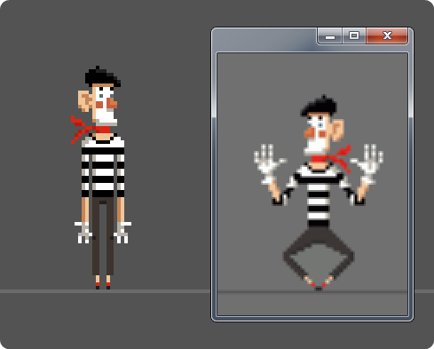
A small test of attentiveness:

Next, we will discuss the factors that distinguish the top image from the bottom, and how to eliminate them. If there are no such problems in your applications, try turning on the mode of increasing the text and interface elements in the Windows settings - most likely problems will appear. Owners of small screens with high resolution or just people with poor eyesight often use this feature.

It is not necessary to read everything completely, you can restrict yourself to viewing illustrations. Perhaps you will remember them, and you will return to this guide when you really need to fight for the clarity of the graphical output of your application.
Each section of the manual is equipped with a demonstration application illustrating the problem under consideration and methods for solving it. You can download everything as a single archive (104 Kb) containing the combined modules and their source code (VS2010 project format).
So where does WPF come from and how to deal with it?
1. Scaling bitmaps
When working with raster images, the most common cause of “blurring” is scaling on output. Set the Image element dimensions that do not match the physical size of the image, and the result will no longer be similar to the source. Automatic adjustment of the size of the image to the size of the container often leads to a similar result. In this case, the reason for the appearance of artifacts is the need to transfer the image from one raster grid to another.

Opposition
If the image in the scaling container was in error, then you need to get it from there. If the image sizes are wrong, you need to adjust them. It's simple. But only as long as you are testing your application with standard settings. If you enable the mode of enlarged fonts and interface elements in Windows, the resolution of the output of the WPF application will change, the virtual unit of measure will become larger than the pixel size, and your bitmap image will be hopelessly corrupted by stretching.
If your plans do not include image scaling for users with enlarged fonts, you will have to make corrections on the fly. First you need to know the current output resolution and its relation to the standard one. For example:
public static class Render { static Render() { var flags = BindingFlags.NonPublic | BindingFlags.Static; var dpiProperty = typeof(SystemParameters).GetProperty("Dpi", flags); Dpi = (int)dpiProperty.GetValue(null, null); PixelSize = 96.0 / Dpi; } // public static double PixelSize { get; private set; } // public static int Dpi { get; private set; } } Then you can, in the heir to the standard Image, independently set the dimensions of the image depending on the current output resolution. In XAML, such a picture should be placed without specifying specific sizes.
public class StaticImage : Image { static StaticImage() { // Image.SourceProperty.OverrideMetadata( typeof(StaticImage), new FrameworkPropertyMetadata(SourceChanged)); } private static void SourceChanged( DependencyObject obj, DependencyPropertyChangedEventArgs e) { var image = obj as StaticImage; if (image == null) return; // image.Width = image.Source.Width * Render.PixelSize; image.Height = image.Source.Height * Render.PixelSize; } } 
If scaling is unavoidable, then all you have to do is fight for reducing the degree of distortion by choosing the appropriate output algorithm for your case using the RenderOptions.BitmapScalingMode property.

2. Coordinates not multiples of pixel size.
A fairly simple way to get an unplanned blur is to center the Image in a container (also works for the Rectangle and the other heirs of the Shape ). In half of the cases, the width of the container is not divided completely in half.
However, you can do without centering. A container grid , for example, allows you to divide yourself into parts in arbitrary proportions. Here is a characteristic case, when everything is fine in the upper left cell, fog in the lower right cell, and in the rest - something in between:
<!-- --> <Grid Width="117" Height="117"> <Grid.RowDefinitions> <RowDefinition Height="*"/> <RowDefinition Height="*"/> </Grid.RowDefinitions> <Grid.ColumnDefinitions> <ColumnDefinition Width="*"/> <ColumnDefinition Width="*"/> </Grid.ColumnDefinitions> <!-- --> <Grid.Resources> <Style TargetType="Image"> <Setter Property="Width" Value="48"/> <Setter Property="Height" Value="48"/> <Setter Property="Margin" Value="5"/> <Setter Property="VerticalAlignment" Value="Top"/> <Setter Property="HorizontalAlignment" Value="Left"/> <Setter Property="Source" Value="CookingPot.png"/> </Style> </Grid.Resources> <Image Grid.Column="0" Grid.Row="0"/> <Image Grid.Column="1" Grid.Row="0"/> <Image Grid.Column="0" Grid.Row="1"/> <Image Grid.Column="1" Grid.Row="1"/> </Grid> 
Equally effectively helps to blur the picture task in Canvas indents or positions that are not multiples of the pixel size.
In all these cases, you will receive a “soap”, even if no scaling occurs during the output. The boundaries of the pixels of the image no longer fall within the boundaries of the pixels of the screen, and smears them during rasterization.
Opposition
Everything is simple with containers; setting the UseLayoutRounding property to True causes the container ( Window including) to automatically round the position of the child elements to the nearest integer pixel value. In other cases, it is necessary, one way or another, to explicitly bind coordinates to the boundaries of pixels.
Note that the expression “integer coordinates” means “coordinates that are divided by pixel size completely” only in the standard resolution of 96 dpi, in all other Math.Round does not help you. In the general case, the coordinate can be rounded to the nearest pixel border as follows:
static public double SnapToPixels(double value) { value += PixelSize / 2; // DPI WPF- . // 1000 - // double //2.4 / 0.4 = 5.9999999999999991 //240.0 / 40.0 = 6.0 var div = (value * 1000) / (PixelSize * 1000); return (int)div * PixelSize; } 3. Native resolution of raster images
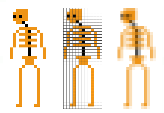
When you first encounter the problem of scaling bitmaps, you will most likely try to google the fact that Image has a magic output mode without scaling. There is such a mode, it is Stretch = "None" , but it is worth hoping for it and removing the explicit assignment of output sizes, as you find yourself in the risk group. Raster images have their own resolution, it is indicated in the metadata, and WPF takes it into account when forming the dimensions of the image. If you do not know what it is, then, with luck, you will be able to believe in black magic: some of the images you have will be drawn as expected, and completely similar to them to swell or shrink under the same conditions.
Download these three images for experiments (each one has a different resolution):


If the resolution of the image does not coincide with the resolution of the output, then when it is loaded, its dimensions are multiplied by the ratio of permissions, and when drawn in the “original” size, you suddenly get scaled. By the way, the StaticImage class shown in the first method is also not protected from these distortions, since it relies on the Source.Width and Source.Height properties .
None of the graphic editors or viewers will be waving image resolution controls in front of you. Moreover, some of these programs do not show at all and do not allow this parameter to be changed. However, it is important.
<!-- , --> <Grid> <Grid.ColumnDefinitions> <ColumnDefinition Width="Auto"/> <ColumnDefinition Width="Auto"/> <ColumnDefinition Width="Auto"/> </Grid.ColumnDefinitions> <Image Grid.Column="0" Source="Man1.png" Stretch="None" Margin="5"/> <Image Grid.Column="1" Source="Man2.png" Stretch="None" Margin="5"/> <Image Grid.Column="2" Source="Man3.png" Stretch="None" Margin="5"/> </Grid> 
Opposition
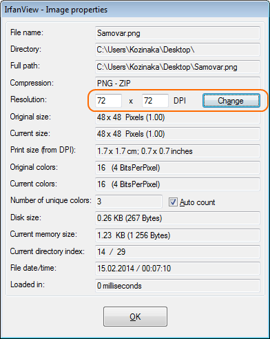
In order for the dimensions of the image in virtual units to match its size in pixels, you need to set the resolution in the graphical editor to 96 dpi. With the image itself, nothing will happen when the resolution is changed, only the metadata will change.
Standard Paint will not work for this, you will need something more serious. In the popular free viewer IrfanView, you can set the resolution in the image properties display dialog (hotkey I):
In the at least free Paint.NET editor, the same effect can be achieved by going to the “Image” menu, then “Canvas size ...” (hot key Ctrl + Shit + R).

If you do not want or can not work with the resolution in the graphical editor (for example, your application works with loaded custom images), you can change the resolution of the loaded image programmatically. Here is an example of the load function for 32-bit images:
// Image.Source 96 dpi BitmapSource ConvertBitmapTo96DPI(string path) { var uri = new Uri(path); var bitmapImage = new BitmapImage(uri); int width = bitmapImage.PixelWidth; int height = bitmapImage.PixelHeight; int stride = width * 4; // 4 var pixelData = new byte[stride * height]; bitmapImage.CopyPixels(pixelData, stride, 0); return BitmapSource.Create( width, height, 96, 96, PixelFormats.Bgra32, bitmapImage.Palette, pixelData, stride); } 4. Rasterization of vector images
From the description of the first three reasons for the emergence of "soap" you may have the well-founded opinion that there are some problems with raster images in WPF. Indeed, it is much more natural to use vector images to work in a vector environment. In the first experiments, the transformation of SVG to XAML seems to be a panacea, allowing you to no longer think about sizes and pixels. Alas, it is not. Exactly at midnight, the carriage turns into a pumpkin, and the vector image is rasterized for display on the screen.
The smaller the output pixels, the more artifacts. On images with a size of 48 pixels or less (this is almost 80% of all graphics in desktop applications), the situation degenerates into the following: the vector image is correctly rasterized in only one resolution, which is optimized, in the others already because. Display the vector icon is not in the amount for which it was prepared, and the inexorable anti-aliasing will not take long.


Opposition
In some cases, you can do a simple increase in image size. For example, for buttons on the toolbar, use pictures with the size of 32x32 pixels, and for the context menu icons 25x25. However, if you really care how the vector icon will be rasterized, then you need to optimize it for a specific resolution - the necessary image details should coincide with the borders of the pixels of the output raster.
5. Moving text vertically
When displaying text, WPF uses some kind of sharpening technique. While the text is static, it looks as clear as possible for its position and the selected rasterization mode (.NET Framework 4.0 and higher). When moving along the vertical, at some values of the shift, the “sharpilka” turns off abruptly and then smoothly turns back on.
Here is an example of a parasitic blur effect on a button with text animation when pressed:
<Button VerticalAlignment="Top"> <Button.Template> <ControlTemplate TargetType="Button"> <Border Width="255" Height="40" BorderThickness="1 0 1 1" CornerRadius="0 0 10 10" BorderBrush="#FF202020" Background="#FFF7941D"> <StackPanel Name="Panel" Orientation="Horizontal"> <Label Content=" " Foreground="#FF202020" VerticalAlignment="Center" Margin="20 0 0 0" Padding="0"/> </StackPanel> </Border> <ControlTemplate.Triggers> <Trigger Property="IsPressed" Value="True"> <Setter TargetName="Panel" Property="Margin" Value="3 1 -3 -1"/> </Trigger> </ControlTemplate.Triggers> </ControlTemplate> </Button.Template> </Button> 
The blur conditions in this example are rather mysterious. Apparently, the combination of the absence of the upper border, nesting of the text in the StackPanel (in the real situation in the button there was another picture) and a sharp shift of the text down by one or two pixels works.
Opposition
In the .NET Framework 4.0 and higher, using the TextOptions attribute , you can choose from two text rasterization modes: Ideal and Display . This will slightly reduce the unpleasant blur effect. In previous versions of the framework, the rasterization mode corresponds to the Ideal mode - as the letter on the pixel grid falls, it will rasterize. In Display mode, intermediate processing is used: the text horizontally is always clearly tied to the pixels, and the same letters are rasterized in the same way. For more information about the modes of text output can be read here and here .
The blur effect of sharp text movement is easy to reproduce in the lab. It is enough to move it vertically to positions that are not multiples of the pixel size. Below is an example of parallel movement of three blocks of text. The two upper blocks with the same output mode blur differently. Obviously, it is not the amount of shift that matters, but the position of the text relative to the raster grid.
The mere fact of moving text does not necessarily lead to a “dynamic blur”. If this effect occurs, it affects the entire line. Alas, the developer does not provide the means to control this effect. In some cases, its occurrence can be avoided if the block coordinates are aligned with the pixel boundaries or the shift value is chosen experimentally.
6. Using the SnapsToDevicePixels property
If you use such basic visual elements as Rectangle , Ellipse , Line , Path , Border , etc., then when displayed in coordinates that are not multiples of the pixel size, they will surely show you the blurring of vertical and horizontal lines. Here is an example of an image constructed using the indicated elements:
<!-- --> <Grid HorizontalAlignment="Center" VerticalAlignment="Center"> <Grid.RowDefinitions> <RowDefinition Height="10"/> <RowDefinition Height="20"/> </Grid.RowDefinitions> <Grid.ColumnDefinitions> <ColumnDefinition Width="25"/> <ColumnDefinition Width="6"/> </Grid.ColumnDefinitions> <!-- ( , ) --> <Ellipse Grid.Column="0" Grid.Row="0" Grid.RowSpan="2" Fill="Black" Width="10" Height="10" VerticalAlignment="Top" Margin="15 5 0 0"/> <Line Grid.RowSpan="2" X1="10" X2="20" Y1="1" Y2="11" Stroke="Black"/> <Line Grid.ColumnSpan="2" Grid.RowSpan="2" X1="30" X2="20" Y1="1" Y2="11" Stroke="Black" /> <!-- ( ) --> <Border Grid.ColumnSpan="2" Grid.Row="1" Background="#FFF7941D"/> <Rectangle Grid.Column="0" Grid.Row="1" Fill="White" RadiusX="3" RadiusY="3" Margin="2.5"/> <!-- ( 1, ) --> <Line Grid.Column="1" Grid.Row="1" StrokeThickness="1" Stroke="Black" X1="0" X2="4" Y1="3" Y2="3"/> <Line Grid.Column="1" Grid.Row="1" StrokeThickness="1" Stroke="Black" X1="0" X2="4" Y1="5" Y2="5"/> <Line Grid.Column="1" Grid.Row="1" StrokeThickness="1" Stroke="Black" X1="0" X2="4" Y1="7" Y2="7"/> </Grid> 
In the illustrations below, the control with a demo picture moves in 0.2 pixel steps. First, he does it separately along each of the axes, then along an arc of a circle. Depending on the phase of the movement, the local coordinate grid of the control is superimposed on the physical raster grid in different ways.


Sometimes it’s clear the outer edges of the TV, sometimes the borders of its screen, but it never happens at the same time. The buttons are clear either horizontally or vertically, and more often blurred along both axes. The antenna in any combination is slightly smoothed and does not complex about this.
Opposition
You can turn on pixel snapping in controls by setting the SnapsToDevicePixels property to True (to do this, simply set this attribute on the root grid). The result will be more stable:

However, the picture is neither immutable when moving, nor ideally attached to pixels. The TV screen shakes within one pixel along both axes, and its buttons are always blurred.
Setting the SnapsToDevicePixels property to True recommends that the visual element, when drawn, be within the borders of pixels on the screen with its borders. Each control will strive to do this with different zeal and in different ways. For example, Image , Label and TextBlock are completely indifferent to this attribute. Line will fall into pixels only if the original geometry is successful. Rectangle , on the contrary, will jump out of his pants and always fall into pixels.
For a more stable pixel binding, you need to adjust the original image:
- add 0.5 to all Y-coordinates of the lines depicting the buttons so that their edges coincide with the pixel grid in the control space;
- indent the TV screen as an integer, for example 2, so that it does not wind by binding to the nearest pixel boundaries.

By the way, these actions will help to get a clear and stable output only in the standard resolution of 96 dpi, in the rest there will be confusion and vacillation. To hit the pixels in any resolution you should refer to the recommendations of the section “Independent drawing of controls” (the dimensions of the controls will have to be adjusted on the go, based on the physical pixel size).
7. Independent drawing of controls
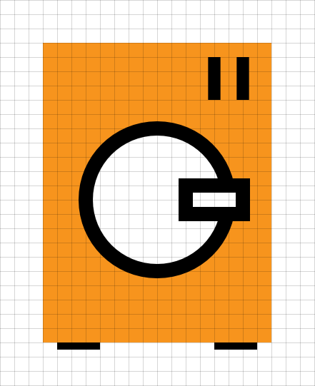
If you overlap OnRender in your visual element and draw it yourself using the DrawingContext , then you have exactly the same rasterization problems as the heirs of the Shape from the previous method, but you must implement the SnapsToDevicePixels functionality yourself. If, of course, you want. You can not bother and do something like this:
public class Washer : FrameworkElement { public Washer() { _brush = new SolidColorBrush(Color.FromRgb(247, 148, 29)); _brush.Freeze(); _pen = new Pen(Brushes.Black, 1); _pen.Freeze(); } protected override void OnRender(DrawingContext dc) { // dc.DrawLine(_pen, new Point(1, 21), new Point(4, 21)); dc.DrawLine(_pen, new Point(12, 21), new Point(15, 21)); // var rect = new Rect(0, 0, 16, 21); dc.DrawRectangle(_brush, null, rect); // dc.DrawLine(_pen, new Point(12, 1), new Point(12, 4)); dc.DrawLine(_pen, new Point(14, 1), new Point(14, 4)); // dc.DrawEllipse(Brushes.White, _pen, new Point(8, 11), 5, 5); // rect = new Rect(10, 10, 4, 2); dc.DrawRectangle(Brushes.White, _pen, rect); } private Pen _pen; private Brush _brush; } Despite the fact that all the specified coordinates are integer, the imposition on the pixel grid in the control space will occur as follows:
 The width of the pen is counted in both directions from the given coordinates of the line. If the half of the pen is not divided by the width of the pixel completely, then the edges of the line do not fall into the borders of the pixels, even if the given coordinates fit them exactly. If the image is complex, then it may turn out that the image is not shifted, but it’s impossible to ensure that all its components are clear. The illustration shows the movement of the image in increments of 0.2 pixels.
Opposition
WPF provides special pixel-binding facilities - guidelines . At the stage of forming a chain of actions for drawing a control (this is exactly what the OnRender method does ) you can specify the vertical and horizontal coordinates in the control space, which, when output, should fall exactly within the pixel boundaries.

In code, it looks like this ( OnRender method only ):
protected override void OnRender(DrawingContext dc) { double halfPen = _pen.Thickness / 2; // var snapX = new double[] { 1, 12 }; var snapY = new double[] { 21 + halfPen }; dc.PushGuidelineSet(new GuidelineSet(snapX, snapY)); dc.DrawLine(_pen, new Point(1, 21), new Point(4, 21)); dc.DrawLine(_pen, new Point(12, 21), new Point(15, 21)); dc.Pop(); // snapX = new double[] { 0, }; snapY = new double[] { 21 }; dc.PushGuidelineSet(new GuidelineSet(snapX, snapY)); var rect = new Rect(0, 0, 16, 21); dc.DrawRectangle(_brush, null, rect); dc.Pop(); // snapX = new double[] { 12 - halfPen }; snapY = new double[] { 1 }; dc.PushGuidelineSet(new GuidelineSet(snapX, snapY)); dc.DrawLine(_pen, new Point(12, 1), new Point(12, 4)); dc.DrawLine(_pen, new Point(14, 1), new Point(14, 4)); dc.Pop(); // snapX = new double[] { 3 - halfPen }; snapY = new double[] { 6 - halfPen }; dc.PushGuidelineSet(new GuidelineSet(snapX, snapY)); dc.DrawEllipse(Brushes.White, _pen, new Point(8, 11), 5, 5); dc.Pop(); // snapX = new double[] { 10 - halfPen }; snapY = new double[] { 10 - halfPen }; dc.PushGuidelineSet(new GuidelineSet(snapX, snapY)); rect = new Rect(10, 10, 4, 2); dc.DrawRectangle(Brushes.White, _pen, rect); dc.Pop(); }  To work with guides, you do not need to know the current output resolution. It is enough to arrange them properly in local coordinates of the control. The above example works correctly only in the standard resolution of 96 dpi, in which the pen width is the same as the pixel size. To achieve clear line boundaries in other resolutions, you will have to assign a guide to each of its sides.
An important nuance is that with the DrawingContext the guides interact through the stack and at the same time affect the entire current output, and not only the shapes, within the boundaries of which they fall. That is why in the example for alignment of two parallel lines only one guideline for each axis is used. If you collect all the used guides and at once push into the stack, then the result will be deplorable. Because of the conflict, only some of them will work, the rest will be ignored.
Alignment to the pixel boundaries along the guides is carried out in both directions, so in different situations different parts of the image can be moved in different directions. When the picture is moved, parts of the washing machine dangle relative to each other, and in some situations the legs disappear. You can change the image by optimizing for stable output at a specific resolution, as was done in the previous section, but you will not be able to achieve stable output at any resolution. Below, an alternative method of snapping to pixels, devoid of this disadvantage, is considered.
Alternative opposition
It is not necessary to use guides to bind to pixels when drawing controls independently. Cycling lovers can fall within the pixel boundaries by manually correcting the primitives drawn. It is not as difficult as it may seem. The following conditions will be required:
- the coordinates of the source data should fall within the pixel boundaries. For 96 dpi, you can use Math.Round , for the general case you will have to round it to a specific pixel size;
- the width of the pens used must be a multiple of the pixel size;
- in cases where the width of the pen contains an odd number of pixels, the coordinates of the displayed primitive must be shifted by half the width of the pixel;
- when displaying a control, it is necessary to make a correction for the shift of its coordinates relative to the raster grid and restart OnRender for any of its movements.
The first two points can be implemented using such a static class (its fragments were given in the first two sections):
// public static class Render { static Render() { var flags = BindingFlags.NonPublic | BindingFlags.Static; var dpiProperty = typeof(SystemParameters).GetProperty("Dpi", flags); Dpi = (int)dpiProperty.GetValue(null, null); PixelSize = 96.0 / Dpi; HalfPixelSize = PixelSize / 2; } // public static double PixelSize { get; private set; } // public static int Dpi { get; private set; } // static public double SnapToPixels(double value) { value += HalfPixelSize; // DPI WPF- . // 1000 - // double //2.4 / 0.4 = 5.9999999999999991 //2400.0 / 400.0 = 6.0 var div = (value * 1000) / (PixelSize * 1000); return (int)div * PixelSize; } private static readonly double HalfPixelSize; } If any value (for example, the pen width or screen coordinate) needs to be tightly bound to the pixel size, then it is enough to set it as Render.PixelSize * n . If you need to round it to a multiple of the pixel size, then you need to use the Render.SnapToPixels method .
It is convenient to implement the third and fourth conditions (correction for subpixel shifts of controls and odd sizes of feathers) as a base class for self-drawn controls:
public class SelfDrawingControlBase : FrameworkElement { public SelfDrawingControlBase() { Snap = 0.5 * Render.PixelSize; SubpixelOffset = new Point(0, 0); LayoutUpdated += OnLayoutUpdated; } protected void OnLayoutUpdated(object sender, EventArgs e) { FixSubpixelOffset(); InvalidateVisual(); } // protected void SnapLine(Pen pen, ref Point begin, ref Point end) { var snapX = -SubpixelOffset.X; var snapY = -SubpixelOffset.Y; if (IsOdd(pen.Thickness)) { if (begin.X == end.X) snapX += Snap; if (begin.Y == end.Y) snapY += Snap; } begin.X += snapX; begin.Y += snapY; end.X += snapX; end.Y += snapY; } // protected void SnapRectangle(Pen pen, ref Rect rect) { var snapX = -SubpixelOffset.X; var snapY = -SubpixelOffset.Y; if (pen != null && IsOdd(pen.Thickness)) { snapX += Snap; snapY += Snap; } rect.Location = new Point(rect.Left + snapX, rect.Top + snapY); } // protected void SnapEllipse(Pen pen, ref Point center) { var snapX = -SubpixelOffset.X; var snapY = -SubpixelOffset.Y; if (pen != null && IsOdd(pen.Thickness)) { snapX += Snap; snapY += Snap; } center.X += snapX; center.Y += snapY; } // protected double Snap { get; private set; } // protected Point SubpixelOffset { get; private set; } // // private void FixSubpixelOffset() { var offset = TranslatePoint(new Point(0, 0), Application.Current.MainWindow); SubpixelOffset = new Point( ModByPixel(offset.X), ModByPixel(offset.Y)); } // private static bool IsOdd(double value) { // DPI WPF- . // 1000 - // double //1.0 % 0.1 = 0.09999999999999995 //1000.0 % 100.0 = 0.0 return (value * 1000) % (Render.PixelSize * 2 * 1000) != 0; } // private static double ModByPixel(double value) { return ((value * 1000) % (Render.PixelSize * 1000)) / 1000; } } The main functionality of this class is to correct the coordinates of graphic primitives before their output. SnapXXX methods change the source data so that the drawing result falls exactly within the pixel boundaries.
Rectangles and ellipses can only be shifted entirely by half a pixel with feathers of odd width. For horizontal lines, you need to adjust the Y coordinate and not touch the X coordinate, for the vertical lines - on the contrary. When adjusting the coordinates, the shift of the control relative to the pixel grid is also taken into account.
Snap to pixels in the washing machine example:
public class Washer : SelfDrawingControlBase { public Washer() { _brush = new SolidColorBrush(Color.FromRgb(247, 148, 29)); _brush.Freeze(); _pen = new Pen(Brushes.Black, 1); _pen.Freeze(); } protected override void OnRender(DrawingContext dc) { // Point start = new Point(1, 21); Point end = new Point(4, 21); SnapLine(_pen, ref start, ref end); dc.DrawLine(_pen, start, end); start = new Point(12, 21); end = new Point(15, 21); SnapLine(_pen, ref start, ref end); dc.DrawLine(_pen, start, end); // var rect = new Rect(0, 0,16, 21); SnapRectangle(null, ref rect); dc.DrawRectangle(_brush, null, rect); // start = new Point(12, 1); end = new Point(12, 4); SnapLine(_pen, ref start, ref end); dc.DrawLine(_pen, start, end); start = new Point(14, 1); end = new Point(14, 4); SnapLine(_pen, ref start, ref end); dc.DrawLine(_pen, start, end); // var center = new Point(8, 11); SnapEllipse(_pen, ref center); dc.DrawEllipse( Brushes.White, _pen, center, 5, 5); // rect = new Rect(10, 10, 4, 2); SnapRectangle(_pen, ref rect); dc.DrawRectangle(Brushes.White, _pen, rect); } private Pen _pen; private Brush _brush; }  The result is obtained in a similar way with guides, but at the same time stable with respect to movements of the control. This is due to the fact that the correction of coordinates is carried out only in one direction.
The above solution of the example works only in the standard resolution of 96 dpi - pen sizes and primitive coordinates are inserted into the code with specific numbers for clarity. If you need the image to be correctly attached to pixels in any resolutions, then before transferring data to SnapXXX methods , you need to round them to the pixel boundaries using the Render.SnapToPixels method .
Here, for example, the control that draws a rectangle, which is adequately scaled when the resolution is changed and thus falls within the boundaries of pixels:
public class CrossDpiBrick : SelfDrawingControlBase { public CrossDpiBrick() { _brush = new SolidColorBrush(Color.FromRgb(247, 148, 29)); _brush.Freeze(); _pen = new Pen(Brushes.Black, Render.SnapToPixels(7)); _pen.Freeze(); } protected override void OnRender(DrawingContext dc) { var rect = new Rect(Render.SnapToPixels(10), Render.SnapToPixels(10), Render.SnapToPixels(120), Render.SnapToPixels(40)); SnapRectangle(_pen, ref rect); dc.DrawRoundedRectangle(_brush, _pen, rect, Render.SnapToPixels(10), Render.SnapToPixels(10)); } private Pen _pen; private Brush _brush; } 

Manual snapping to pixels requires a little more intervention in the drawing process than when working with the built-in WPF tools, but it allows you to more flexibly control this process and to achieve stable output at any output resolution.
Conclusion
WPF provides the developer with all the necessary set of tools to bind to screen pixels. In the standard library of controls, these tools are used by default, and in most cases you can not sabotage yourself with subpixel shifts. However, to achieve a clear conclusion when working with vector and raster graphics, as well as when drawing controls independently, the developer is forced to use pixel snapping tools explicitly.
For this, first of all, it is necessary to notice the arising rasterization problems. It is not so easy. Even the products from Microsoft can not always boast the perfect picture. For example, the elements of the integrated vector graphics editor in Microsoft Word 2010:

Familiar artifacts? If now for you the elimination of such detected problems is a matter of technology, the goal of this manual is achieved. Thanks for attention!
Links
The MSDN - Pixel Snapping in the Applications a WPF
the MSDN - UIElement.UseLayoutRounding the Property
Pete Brown is - your Fonts-in Choose the Text and the Rendering the Options Wisely
the MSDN Blogs - a WPF 4.0 the Text the Stack Improvements
the MSDN - How to: the Apply a GuidelineSet to a the Drawing
the MSDN - UIElement.SnapsToDevicePixels the Property
Source demo code: download (104 Kb)
Thanks for the illustrations:
 romson
 melkopuz
 sevendot
Source: https://habr.com/ru/post/216833/
All Articles