Autonomous quadcopter from scratch: PID and rake
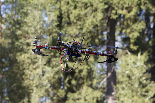 Most of the projects using copters rely on manual remote control, there are no fully autonomous systems yet. But for industrial use it is necessary; The human factor is the cause of most accidents. Below, the story goes about how we made our stabilization system using the PID , which allows us to minimize human involvement in the process of the drone.
One of the test flights of our copter
When creating robots autonomous at a high behavioral level, it is necessary to work with all lower levels of autonomy, starting with stabilization in a given position. Therefore, we started by creating our own stabilization board.
Definition of autonomy
Autonomy is determined relative to the task. If the task is for the robot to follow the GPS coordinates initially set (for example, skirting obstacles in its path), then by autonomy we mean independent decision making by the robot from the moment the route and task were received. Autonomy at a higher level is, for example, independent choice of a route when “patrolling” a certain territory. The initial data will be information about this territory.
PID
The simplest stabilization problem is to control the angle of inclination, but it follows from the laws of the dynamics of rotational motion that only its second derivative can be directly controlled. The easiest way to influence the desired value is to use the FID.
')

MEMS - in our case it is a gyroscope, accelerometer and magnetometer; DMP - Digital Motion Processor; ESC - Brushless Motor Speed Controller.
The generalized coordinate (in our case, the angle) is fed to the input of the regulator, at the output we get the moment of forces (the second derivative of the angle). Each PID controller stabilizes the value of one generalized coordinate . We use three PIDs with constant coefficients, one for each corner of Taita-Bryan .
Materiel
We define the discrepancy - the difference between the required and real value of a certain value:

 - the required value (angle from the joystick),
 - the current value of the value (angle from the sensor).
Set the moment of force for the angle
at the current time:
Where
 - proportional,
  - integral,
  - differential components.
The minus sign says that with positive
 ,
,  ,
,  Impact directed against deviation.
What is the meaning of this formula? We write the equation of dynamics, putting
 .
.
 - moment of inertia.
For simplicity, remove the integral component (
 ). After redesignation of the coefficients, we obtain the equation of damped oscillations with respect to :

Where

That is, the larger the proportional component, the more “sharp” will be the reaction to the impact (the greater the amplitude). The larger the differential component, the faster the attenuation will occur (the greater the decrement).
From the model of damped oscillations, we obtain the expression for the damping coefficient:


Of the possible solutions of the equation, we are approached by a regime close to the critical one (the boundary of aperiodicity,
 ) - there is no negative “flight” schedule, the transition process is short. As you can see, the critical mode is set by just one ratio to the PID controller coefficients.
Integral component eliminates static error. Let discrepancy
 small and constant, then the differential component is zero, and the proportional can be so small that to account for it is not enough accuracy ESC. In this case, the rotor will not tend to the desired position. But if we sum up the small deviations then after some finite time the total deviation will be enough to compensate for the static error. Coefficient determines this time: the greater the value of the coefficient, the earlier the system begins to take into account the increasing error. In this case, too large an integral component leads to self-oscillations.
A more detailed analysis of the PID controller equation can be found in other articles: one , two .
First accident
Too large differential component in practice leads to self-oscillations, which should not be in theory. Why? Remove all components except the differential, and solve the equation:
 - exhibitor, no hesitation!
The reason for this effect is the large response time of the system (and generally because it is non-zero). Due to the phase shift caused by system latency, the function argument
 gets some decrement:

i.e. value
turns into a linear combination and its derivative. The same happens with the moment of forces, which is also a harmonic function in this example. With certain  linear combination coefficients may be such that persistent self-oscillations occur.
Also, the result of the work of the components of the PID has to be limited by module. Otherwise meaning
for example, will grow to overflow. With the other two components, a problem also arises: it is necessary to achieve a fast reaction to an external influence in the vicinity of the position being set. For this, the coefficients should not be too small. But with large deviations (which are also possible in flight), large coefficients will lead to self-oscillations of large amplitude.A compromise is to set not too small coefficients together with the introduction of a top limit on all three components: proportional, integral and differential.
It is worth saying that the real correction in an almost horizontal position is about 1–2

Consider the solution of the second order equation (1), which in one of the cases is a damped sinusoid.
In practice, something similar is really obtained (the example on the right). For demonstration, the coefficients are specially degraded to increase the decay time. The original ESC firmware had to be replaced, since it introduced a significant delay, due to which the mathematical model poorly described the real system.

Insofar as
-the component is proportional to the angular velocity, it is possible to come to the idea to feed the readings of the gyroscope to the input of the regulator instead of using a discrete difference scheme. In this case, it is important not to forget to add the derivative of the required angle from the remote control to the input; without this, the control will be slow. The graph on the left shows how important the differential component is in control.PID calibration
According to the behavior of the system (real-time component graphs), it is possible to assess exactly which coefficient leads to an undesirable effect. Therefore, they can easily pick up manually (or guess), for which we used a stand with a flexible suspension.


For corners
 and
and  we hung it for the opposite axis of the test, and for the angle
  We used 4 ropes symmetrically fixed on the frame not far from its center.
Although this approach is not the most effective (we do not know the “expiration date” of the coefficients quantitatively and consider them constants), in practice we have solved the problem of stabilizing the kopter in flight. True, there was a problem with management, but more on that later.
The values on which the behavior of the apparatus depends
We obtained experimental confirmation that the PID controller coefficients depend significantly on the internal factors of the system. In the future, it makes sense to conduct a series of experiments to identify the dependence of the coefficients on the following factors.
Internal factors
| Parameters of propellers (diameter X step) | The larger the propellers, the smoother the behavior of the copter. |
| Copter dimensions (distance between the center of the frame and the axes of the motors) | The larger the size, the smoother the behavior of the copter. |
| Fully equipped copter weight | The higher the mass, the smoother the behavior of the copter |
| Battery Charge (Voltage) | The higher the charge, the more dynamic behavior potentially achievable in a copter |
External factors
Air temperature | The warmer the air, the lower the density. As a result, smoothness rises |
| Atmosphere pressure | The greater the pressure, the higher the density. As a result, smoothness decreases. |
Relative humidity | The higher the humidity, the higher the water vapor pressure (and air density). As a result, smoothness decreases. |
Wind power in terms of model | Module -FID member is directly proportional to the constant component of the wind force. The variable component of wind power affects - and -components |
Rake
In the case of adjusting the power of the motors, it is necessary to avoid too low and too high power at which stabilization does not work correctly.
On the one hand, there is a minimum power that cannot be reduced, or the motors will simply stop. On the other hand, power reduction may be necessary for the correct operation of the algorithm. If the power (throttle) is reduced too much, the FID can “go off scale” to the bottom. To solve this problem, we limit the available pilot capacity.

Another danger is the influence of side vibrations from the motors on
-component. They generate noise in the regulator and lead to the occurrence of self-oscillations. We have limited the angular velocity from the bottom of the module: the program filter resets all angular velocity values below the threshold. But the problem has not completely disappeared, now we are thinking about a more suitable solution.The third pitfall is that the use of an integral member of the FID can prevent you from taking off from an inclined surface. Component
accumulates before takeoff, and already in the air, the device is experiencing a bias in the opposite direction. Only after a couple of seconds, during which the copter manages to pick up a significant linear speed, the integral component decreases to values acceptable for flight. To solve this problem, it is possible to turn on the integral component only after the thrust of the motors reaches the take-off value (about 50% of the maximum), while the kopter is already off the ground.Software
 The figure shows a simplified block diagram of the program executed on the controller of the stabilization board. The main part is the cycle. If at least one action in it is not performed on time, the frequency ceases to be constant, and stabilization does not work correctly.
We used the MPU-6050 as a dynamic sensor due to its computational capabilities. The embedded processor (DMP) is able to partially process the data from the sensors, which allows the central controller to be unloaded. But it turned out that reliable libraries for working with this device under Arduino do not exist. Jrowberg's solution led to problems when used on a heavily loaded microcontroller. The code in the example is based on the synchronism of reading data. The sensor's FIFO buffer, in which the calculated values are written, overflows in the event of a late reading. Since the first element is always read from the FIFO, when partially filled, there is a delay between placing the new data in the FIFO and processing it on the Arduino. In turn, this delay leads to self-oscillations. At overflow, the buffer has to be cleared: its size is 1024, which is not divided by 42 — the packet size. Therefore, when the buffer is full, at the beginning of the FIFO there is a part of some extraneous packet. In other words, starting from a certain moment the structure is broken: the beginning of the FIFO does not coincide with the beginning of the packet, and it is impossible to read the correct data.
In addition, it was necessary to change the formula in the library for the conversion of “quaternion angles” in order for the result to be from the full range of angles. Details of this problem are described on the project tracker: https://github.com/it-workshop/Quadrocopter/issues/18 .
Onboard electronics
The main component that we developed independently is the stabilization board. Initially, it was based on the Arduino Uno platform, then replaced with a more powerful Due, which made it possible to increase the frequency of the PID controllers from 40Hz to 66. (6) Hz.
Copter propellers are driven by compact brushless motors in conjunction with standard revolutions controllers - ESC. We use ESC with modified firmware.
More about ESC
The ESC controller standard uses a square wave as the control signal, the control parameter is the duty cycle. In our case, the signal from the remote control is initially received by the stabilization controller, which at its output will forcefully generate the signal required for the ESC. If you refuse such an interface (PWM), due to which you have to convert additional data, you can reduce the system response time. But designing our own motor controller is a separate task that we have not yet considered.
To power the entire system uses a lithium-polymer battery (3S). For safety reasons, we decided to make a battery voltage monitoring system. In normal mode, the use of batteries, the system behaves quite stably. However, in the initial stages of work, we observed the effects caused by the non-optimal use of batteries:
- Swollen batteries. The reason is in recharging and long-term storage of discharged batteries. Manufacturers recommend not discharging power batteries below 3.3V per each battery bank, which in our case gives the minimum allowable voltage of 9.9V.
- Turn off the motors at low voltage. This is a feature of the reaction of most ESC firmware at low voltage, which can lead to a serious accident - at the first moment only one motor turns off, the rest continue to work.
For our purposes, ESC was decided to reprogram. Through the use of tgy firmware (from SimonK), we have achieved a reduction in system latency from the central controller to the engines. As a result, the PID components and the angular velocity became more sinusoidal, and the behavior of the entire system approached the behavior of the mathematical model.
The following sensors are used to measure dynamic parameters:
- 6-axis accelerometer gyro InvenSense MPU-6050
- 3-axis compass Honeywell HMC5883L
Telemetry
Remote control is implemented in two modes (to provide a more flexible development process):
- With the help of xBee Pro modules in the configuration of the "PC kopter".
- Using a dedicated radio frequency (2.4 GHz) in the configuration of the “remote control ↦ copter”.
In addition to control via the remote control, the critical data are transferred between the copter and the PC in real time, for which xBee Pro and its own application are used (see screenshot). On the computer you can see the value of angles and angular velocity, the voltage on the battery, the power of the engines. It is possible to adjust the PID coefficients in real time. The program saves all incoming data and supports the subsequent playback of recorded files, which helps with debugging. In case of emergency, we can stop the motors from the computer.

Data sent between the copter and PC:
- PC ↦ Copter: control channel (PC / remote control), motor power, setting for on / off stabilization, PID coefficients and limits;
- Copter ↦ PC: angles, angular velocity, components , , , data from the joystick (power + 3 angles), the power of the motors, the voltage on the battery.
Thanks to the InvenSense sensor, the initial data processing from the sensors takes place on an embedded processor (DMP). We unload the stabilization board, which even a low-power AVR microcontroller can use as a calculator.
Reproducible results
To create such a device, you need to assemble a similar mechanical design, equivalent electronic circuit and use our software.
Project code: github.com/it-workshop/Quadrocopter/tree/MPU-6050-Compass (distributed under the terms of the MIT license).
Additional info about what we made of our kopter and what was the budget
The frame design greatly influences the flight characteristics. After experimenting with the materials, we came to the following.
- The foam frame allows you to build an extremely light, but not rigid system. The copter appears substantial sail. From this material, it makes sense to make small systems (microcopters) that will fly indoors.
- Plywood truss frame is the least successful solution. Much time to assemble because of the large number of small parts. The rigidity of the system can be achieved with the help of additional sizing of the nodes of the frame, but then it becomes non-separable. Reliable frame turns massive and has a noticeable windage. The strength is low, usually after a hard landing you need to properly glue the cracks or change the bearing parts. Of the benefits worth noting extremely low price.
- One of the most successful materials is aluminum. We used the popular X-525 model. The stiffness is quite high, the frame can be damaged only as a result of a serious accident. Windage and weight are optimally low. The disadvantage is unrecoverable small gap in the joints of the frame parts.
- Composite carbon fiber has extremely high strength at a fairly low density. We used the Talon model. Since carbon is extremely difficult to process without special equipment, we had to order finished parts and apply them without any modifications. Due to the fact that the connecting nodes in carbon frames are usually made of plastic or aluminum, difficult to adjust the places are formed at the joints, that is, there are frequent problems when working with a circular carbon profile: poor alignment of engines and play in the junction points.
Parts List
| Component | Price | amount | Link |
|---|---|---|---|
| Rama Talon | 1100 rub. | one | Hobbyking |
| Battery 3S, 11.1V | 475 rub. | one | Hobbyking |
| Propellers 10x4.5, 10x4.5R | 150 rub. | four | Toyhobby |
| Turnigy Brushless Motors | 330 rub. | four | Hobbyking |
| Esc | 290 rub. | four | Hobbyking |
| 2.4GHz remote control, 4 channels, with receiver | 875 rub. | one | Hobbyking |
| Arduino Due | 2590 rub. | one | amperka.ru |
| Arduino Wireless Shield | 790 rub. | one | amperka.ru |
| InvenSence 6050 sensor | 2335 rub. | one | www.lawicel-shop.se |
| Digital compass HMC5883L | 1290 rub. | one | amperka.ru |
| Xbee pro | 2290 rub. | 2 | amperka.ru |
| Antenna for xBee Pro | 704 rub. | 2 | wifimag.ru |
| Total | 18523 rub. | ||
Directions for development
- The process of testing the stabilization system can be simplified using a more advanced stand. The rope variant is more likely a one-time solution, a hard gimbal suspension with three degrees of freedom would be more appropriate.
- There are methods for automating the selection of PID controller coefficients. For example, based on binary search (branch and bound method). In our project, the coefficients were selected manually.
- A PC application used for monitoring and control would be more convenient to use on a tablet PC. Plans to port the application on Android or IOS.
Results
The main achievement is an excellent team of enthusiasts who are able to work on complex robotic projects. We believe that the whole thing is in creative approach, the possibility for self-realization, as well as invaluable practical experience, which is always lacking.
We have created a new draft stabilization system for multicopter. Now we can pilot a quadrocopter in open space. External factors such as wind, rain and snow are automatically compensated by the PID controller.
We are currently improving what we have done and are developing new automation features.
Copter flight with our stabilization system
summer 2013.
winter 2014.
Spring 2014
About Us
We are MIPT students (in their majority) who, in their free time, are engaged in a project at the TechnoWorks workshop. In addition to the copter, we also have other projects: hardware and software. We will tell about them later on. And here you can come up with and implement your idea (and we will help you find people).
If you want to join our team, contact us! The workshop is actively expanding, for new participants we have a lot of creative and technical work. And cookies.
technoworks.ru
Source: https://habr.com/ru/post/216437/
All Articles