Adding HDD to the "moody" laptop
The fact that you can install a hard drive through the corresponding adapter into the optical drive compartment of the laptop has long been known, and I decided to replace an unused DVD drive with a more useful second drive in my Acer Aspire 5560G laptop. For these purposes, the Espada SS12 adapter was purchased, a hard disk was installed in it, the whole structure was installed in the vacant slot of the laptop, the power button was pressed and ... nothing. Power is being supplied, both hard drives are spinning up, the laptop's LEDs are lit, the cooling fan is quietly spinning and a black screen.
After several attempts to turn on the laptop, I decided to check the adapter itself. It was removed and installed in the DELL Latitude E5410 laptop, in which both the BIOS and Windows discovered a new disk - the adapter is fully functional, and the root of the problem lies somewhere in the depths of the first laptop. After searching for user feedback on attempts to install disks through various adapters, I came to the conclusion that for the most part no one has any problems. And only a small share of reviews (mainly in the comments to this product in online stores) reports that they could not add a second disc.
The first attempts to rectify the situation
Inspecting the adapter stuffing did not add anything new to analyzing the problem - in fact, it’s just a passive adapter between the two SATA data connectors and powering through the Slimline connector to the Standard connector. But there are two additional signals present in the Slimline connector Device present (1 pin) and Manufacturing diagnostic (4 pin), which I found in the English-language Wikipedia section on Serial ATA . The first signal should inform the host controller that disk media is connected to this port, and the second is used by the manufacturer for service purposes. For clarification, the DVD drive was disassembled and both signals were checked. Manufacturing diagnostic was not connected anywhere, but the Device present was connected to GND in the drive through a 1 kΩ resistance. The Espada SS12 adapter has this circuit with resistance R3, but with a different rating of 4.7 kΩ.

')
I initially clung to this version and replaced the resistance, but it did not help. The laptop still refused to start.
Experiment
Structurally, SATA connectors allow hot plugging / unplugging devices, which should be checked. Turning off the adapter with the disk, I start the laptop and press F12 to slow down the BIOS on the choice of device to boot, and connect the adapter - the disk is unwound. Of course, he didn’t appear in the list of drives for loading, and I just choose to boot from a regular disk. Windows booted, determined the new disk, set the correct mode of its operation, the SMART disk was perfectly readable, the speed characteristics were normal. Having run several tests, making sure that there are no restrictions, I decided to check the hotplug to the running system. I turn off, remove the adapter, turn it on, wait for the system to boot, connect the adapter. Everything is fine, the disk is right there and comes into operation.
The result of the experiment: there are no hardware limitations, the problem lies either in the error code of the BIOS during the device initialization stage or in the software limitation that the manufacturer laid.
Solution, version 1
I discarded the BIOS code debugging option in the absence of a programmer at hand. Looking at the insides of the adapter's case, I noticed that there is a rather large unused cavity of the internal volume (in the photo this space is on the left beyond the line marked by me).

Components up to 10 mm high can fit there. I will try to add a power-supply delay circuit to the device. The boxes were searched with broken power supplies and parts of other devices, and the scheme was already scribbled under the parts found.
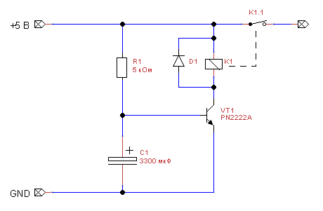
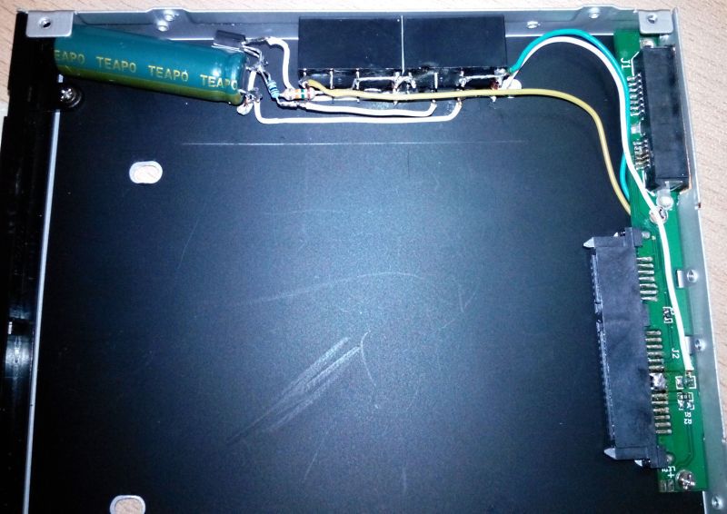
When power is supplied through the resistance R1, the capacitor C1 will start charging, after some time the transistor will open and the relay will operate, supplying 5 V to the hard disk. The assembled mounting scheme fit freely inside the adapter and was glued to a double-sided tape.

Separately, I want to draw attention to the opening of the 5 V supply circuit on the board itself. Initially, I decided to unsolder 7, 8 and 9 pins from the SATA power connector going to the hard drive and thereby solder my circuit. Do not do this! The contact lamellae in the connector are held solely due to the fact that on the one hand they are soldered to the board, and on the other hand, they are attached to the case of the connector. After their taps, they simply stopped holding their places and began to hang out freely. I had to somehow solder them back, which is just seen in the photo above, like a big drop of solder in the middle of the connector pins. In the end, I just cut the 5 V track from the back of the board and plugged into its gap.
I try to turn it on. Power, delay about 2.5 seconds, light click of the relay and spin-up of the second disc. But the BIOS has not yet had time to go through the initialization stage, and the laptop did not start. Well, we increase the resistance of R1 to 15 kΩ. Turning on, the delay is about 8 seconds, by this time Windows has started loading, the click of the relay and the start of the disk. The system sees both drives, fine.
The disadvantage of the scheme is its simplicity. The capacitor is discharged only through the base-emitter of the transistor with a current of about 400 μA, and this does not give the necessary time delay either during a brief power outage, or, especially, when the computer is restarted, which leads to a hangup after switching on. It is necessary to add a capacitor discharge circuit.
Solution, version 2
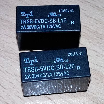
It is impossible to activate the second group of contacts of the used relay to discharge the capacitor, so you will have to add a second relay. By the way, these are the relays I have used, they differ only in the resistance of the coil winding:
The modified scheme looks like this:
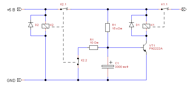
Briefly about the scheme: NC-contact K2.2 discharges the capacitor C1 in the off state of the circuit. When power is applied, K2.2 opens, and K2.1 closes, which starts the old power-supply delay circuit. The installation of the circuit in this case turned out to be more dense, but it still fits inside the adapter:
I isolate the circuit, assemble the adapter, install the hard drive, connect, turn on the laptop. The launch of the disc is now accompanied by two quiet clicks of the relay with a delay of about 8 seconds. Restarting the laptop with power off is normal. A simple reboot results in a hang on diagnostics.
Total
The cost of assembling this scheme will be about 250 p. About 100 p. worth every relay. The remaining parts will either be already in the bins, or will cost several rubles each. Soldering the circuit with all the disassembly and assembly of the adapter will take about an hour. The scheme does not allow you to make a normal reboot of the laptop, because it is tied exclusively to the 5 V power supply circuit. But the scheme allows you to add another hard drive to the "naughty" laptop, and reboots are not needed very often.
Source: https://habr.com/ru/post/215839/
All Articles