To the 45th anniversary of the Apollo-9 spacecraft flight: exposing a popular myth about a lunar module allegedly made of foil
Every time I read the Russian forums in which the topic of man’s flights to the moon is touched upon, I come across absolute ignorance among the members of the forum (including among technically educated people). In RuNet, it is widely believed that the lunar module, designed and built by the Grumman Aerospace Corporation for disembarking a man on the Moon’s surface in the framework of the Apollo program, was made almost from foil. They say the thickness of the walls of his cabin is so thin (most often it is said of three layers of foil) that it can be punched by foot, and the strength of the structure is ensured by internal pressure. This misconception among domestic readers has been dragging since 1976, and is based on the misinterpretation of the phrase by astronaut James MacDivitt, spoken by him at one of the press conferences before the flight of the Apollo-9 spacecraft. Initially, it was misinterpreted by Soviet science fiction writer and journalist Vladimir Stepanovich Gubarev, who wrote the book “Space Bridges”, popular in the USSR (published in 1976 in Moscow by the publishing house Young Guard). Vladimir Gubarev writes (quote from the book):
"R. Schweikart must be very careful. One wrong move, and it will damage the moon cabin. “Its walls are so thin and fragile that a person can punch them with a foot,” said D. McDivitt before the start. “On Earth, the walls of the lunar cabin in many places can damage even the accidentally dropped screwdriver ...”
Another journalist, no less popular popularizer of cosmonautics, Gubarev’s colleague, Yaroslav Kirillovich Golovanov, writes in the well-known book “The Truth about the APOLLO program” (he practically copies his colleague’s text, adding his opinion, which is essentially an amateur’s opinion):
“Schweikart must be very careful,” warned McDivitt. - One wrong move, and it will damage the lunar module. Its walls are so thin and fragile that a person can punch them with their feet. On Earth, the walls of the lunar compartment can damage even the accidentally dropped screwdriver ...
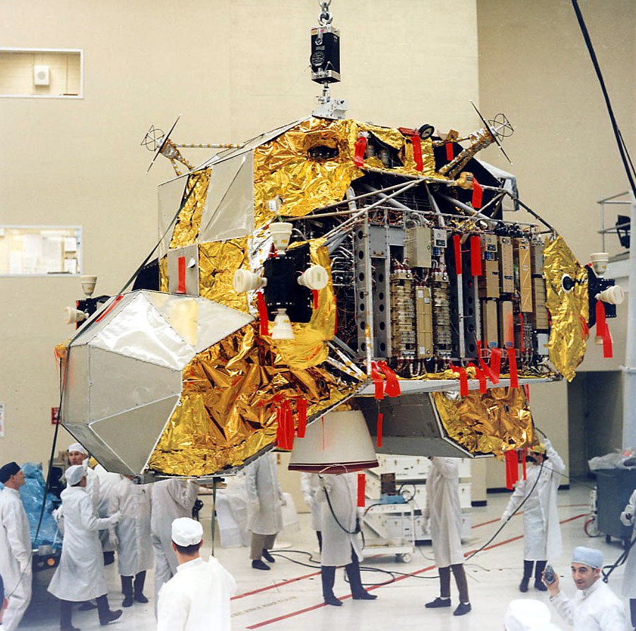
For two weeks I looked at the lunar cabin, which stood in the hall where the press was located during the flight of the Soyuz-19 and Apollo in Houston. "Spider" is made of metal foil. Not from this, of course, in which chocolates are wrapped, but still, if you choose from two definitions: metal sheet or metal foil - foil is more accurate. In vacuum, the rigidity of this structure increased due to internal inflation, but still it remained very subtle. ”( Source )
')

Take-off stage of the lunar module LM-12 of the Apollo 17 spacecraft. Photo of NASA AS17-149-22857
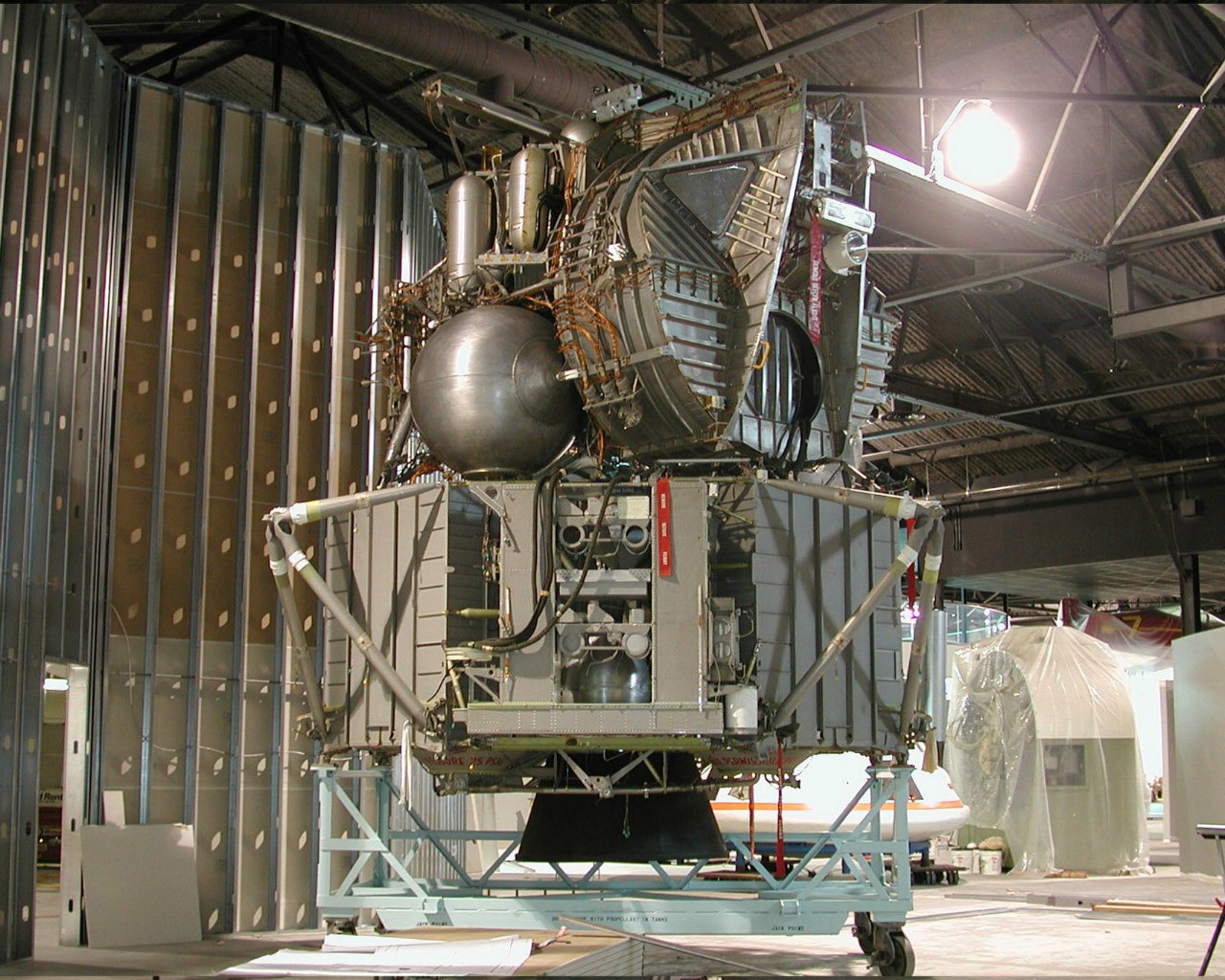
The opinion of Yaroslav Golovanov about the construction “made of foil” and “increasing its rigidity in vacuum” looks especially ridiculous if you look at the photos of the LTA-1 lunar module taken at the Cradle Of Aviation Museum located in the city of East Garden City on Long Island, NY:
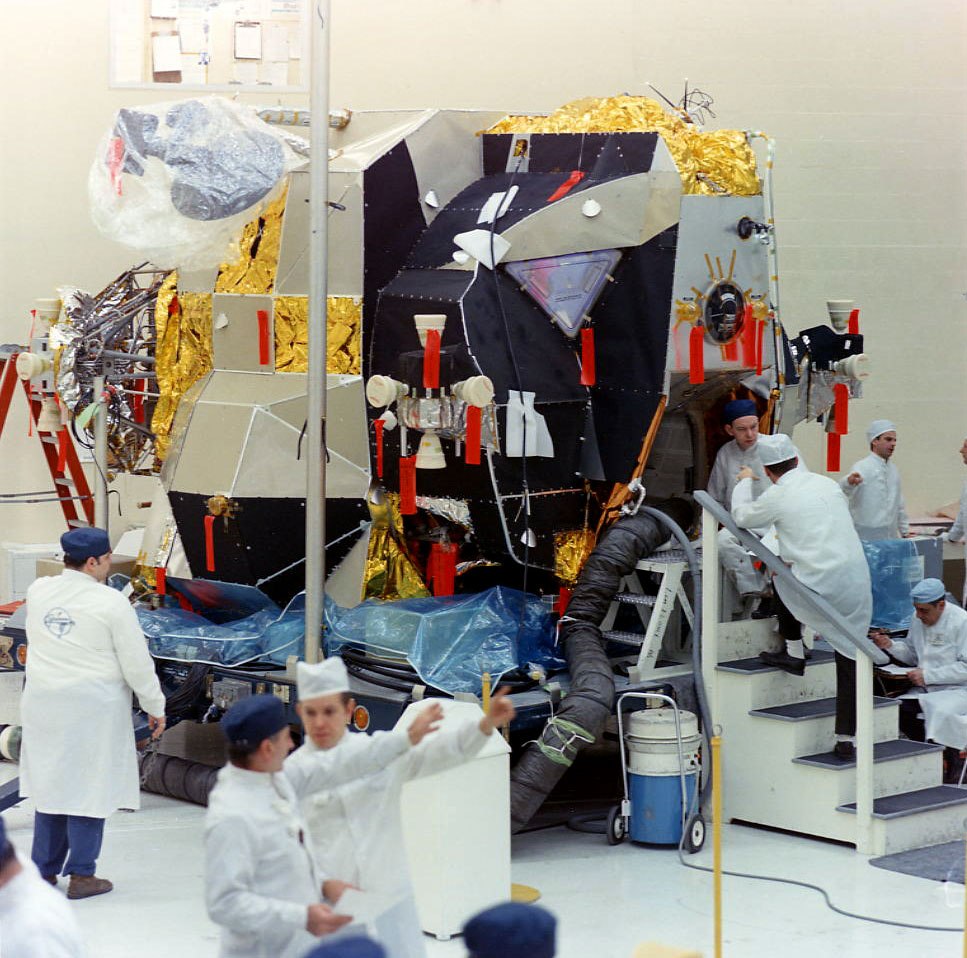
LTA-1 (Lunar Test Article 1) is the first copy of the lunar module (prototype), built in 1966, which is structurally similar to serial samples intended for flights into space. Before LTA-1, Grumman Aerospace Corporation built only full-scale mockups of the lunar module (so-called Mock-Up's: M-1, M-5, TM-1). Structurally, these layouts were made of metal and wood, intended for presentation to the customer (NASA), working out layout solutions for the placement of various auxiliary equipment and training of astronauts. But the power structure of the LTA-1, as well as all the systems (propulsion systems, their mixtures, electrical equipment, etc.) were carried out according to working drawings in compliance with all technological processes. This copy was intended for testing the process of manufacturing, assembling and further debugging the lunar module, when design was still underway, as well as for static, dynamic and electrical tests:

Docking of the take-off and landing stages of the LTA-1 lunar module in a conductive electromagnetic interference test room at the Grumman Aerospace Corporation, City of Betpage, Long Island, New York. Photo of NASA S67-22164
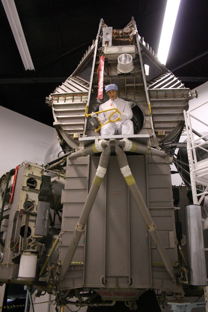
The main design difference of the LTA-1 from the serial samples flying into space is the front hatch, intended for the crew to exit and enter from the take-off stage of the lunar module. On LTA-1 it is round. Starting with LTA-8 and on all serial samples of the lunar module, at the request of astronauts, the hatch was made rectangular. The experiments conducted onboard the NASA “flying laboratory” (reworked Boeing KC-135A Stratotanker tanker) showed that under lunar gravity conditions it was much more convenient for astronauts to squeeze in a spacesuit with a PLSS life support system through a rectangular hatch. In 1974, after the completion of the Apollo program, LTA-1 was deposited with the National Air and Space Museum of the Smithsonian Institution in the city of Washington (DC), and in June 1998 transferred for restoration and further exposure in the Cradle Of Aviation Museum, where it is currently located:


The lunar module of the Apollo spacecraft constructively consists of two stages: the landing and takeoff. The landing stage is equipped with a liquid-propellant rocket engine (LRE) for descending from the orbit of an artificial satellite of the Moon, an approach for landing and soft landing. Landing is carried out on a four-wheel chassis with disc supports. Overloading during landing is reduced due to shortening the legs of the chassis, which are telescopic rods. Kinetic energy when struck on the lunar surface is absorbed by the crumpled filler honeycomb structure of aluminum alloy. The crew, consisting of two astronauts (commander and co-pilot), is located in an airtight cabin of the takeoff stage, which is mounted on top of the landing. Astronauts descend to the surface of the moon is carried out on a ladder mounted on one of the telescopic legs of the landing gear, located on the side of the front hatch. The take-off stage is equipped with a liquid-propellant rocket engine for take-off from the surface (the launching stage at this stage is the landing stage) and an artificial satellite of the Moon entering orbit. Also, the take-off stage is equipped with a reactive control system (DCS). The DCS is designed to control not only the take-off stage, but also the entire lunar module (when it is in a landing configuration) in six degrees of freedom. RSD rocket engines can work in a group or separately - continuously or pulsed. Since the take-off stage accommodates the crew, its design is of the greatest interest within the framework of the mass error under consideration.
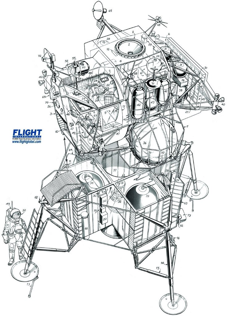

The main structure of the take-off stage of the lunar module is a semi-monocoque structure made of a well-welded duralumin alloy 2219 (the main alloying element is copper) and a high-strength deformable aluminum alloy 7075-T6 (the main alloying element is zinc), which have isotropic characteristics. The main structure consists of three main parts: the crew cabin, the central section and the rear equipment compartment:

Only the cockpit and the central section are sealed. These two parts are welded and forged construction, formed by a cylindrical shell and supported by stringers chained around the circumference, formed from sheet duralumin, as well as transverse milled spars to which the elements of the lunar module takeoff stage are attached (beams, connecting brackets, etc.) .). In the cylindrical part of the cockpit above the commander's workplace, an aperture of the docking porthole was made, reinforced around the perimeter. The front of the cockpit is formed by flat milled panels of sheet duralumin, also supported by stringers and spars at the folds. In front of the cockpit are two triangular openings for the front-view windows, reinforced around the perimeter, and between them, below, the opening for the front hatch (round or rectangular).
According to the technical reports on the lunar module ( NTRS archives), the thickness of the walls of the cockpit shell and the central section of the take-off stage of the lunar module reaches 0.065 inches (1.651 mm). This value exceeds the foil thickness by an order of magnitude (in most countries, the commonly accepted definition of foil is sheet metal thickness up to 0.2 mm), and is thicker than the skin of supersonic Tu-144 (1.2 mm) and Concorde (1.5 mm) aircraft, which were operated in more severe conditions than the lunar module: aerodynamic heating when flying at high supersonic speeds in the stratosphere, cyclic stresses in the hermetic fuselage design due to constant pressure drops, aerodynamic effects (bending, twist), etc. . Have been recorded in the operation of Tu-144 and Concorde cases "foot skin penetration."
In some places (unstressed), in order to reduce the weight of the structure, the wall thickness was reduced by chemical milling to 0.012 in. (0.3 mm).
The main structure of the take-off stage of the lunar module is attached to the propulsion system consisting of the Rocketdyne RS-18 rigidly mounted in the central section of the take-off rocket engine (developed on the basis of the Bell 8247 engine), two fuel tanks for it: from the left side of the central section using supporting rod beams a spherical fuel tank (“Aerosin-50”) was installed; a spherical oxidizer tank (nitrogen tetroxide) was similarly installed from the starboard side of the central section.
Rod beams are attached to the rear section of the central section, as well as to the cockpit through brackets, holding four RSU units with sixteen Marquardt R-4D rocket engines (grouped into four engines). Four cylindrical fuel tanks with hemispherical bottoms are located symmetrically on the side of the left and right sides of the central section. Fuel components are similar to those used in the main propulsion system. Spherical helium tanks for the pressure system of these engines are installed on each side between the fuel and oxidizer tanks for the LRE RSU on each side. Two spherical tanks with water and blocks of transmitting antennas are attached to the upper part of the central section.
Displacement gas (helium) for the main propulsion system is also stored in spherical tanks. They are located in the rear compartment of the equipment, along with two helium pressure reduction modules, a control valve for the main propulsion system (controls the supply of fuel components displaced by helium pressure to the take-off LRD RS-18 combustion chamber) and a control valve with cross-control for the LRE RSU. Also in the rear compartment of the equipment above the spherical tanks with helium there are two spherical tanks with gaseous oxygen for the crew’s life support system. On the special remote panel of the rear compartment of the equipment, the blocks of the radio-electronic equipment of the lunar module are installed which are responsible for radio communication, the operation of the on-board systems (alarm, warning) and the blocks of the on-board digital computer (BCM) responsible for navigation. All systems are interconnected by stranded cables and wires running across the entire surface of the main structure of the takeoff stage of the lunar module. Power is supplied by two silver-zinc rechargeable batteries.
To protect the main structure of the lunar module take-off stage and all the systems described above from the effects of space (temperature drops in vacuum, micrometeorites, rocket engine jets), thermal insulation coating and micrometeorite protection are applied, as well as a special thermal protective paint applied to the micrometeorite protection.
Thermal insulation coating is a multi-segment coating of special multi-layered blankets, each segment of which is stretched onto the skeleton of the main structure of the take-off stage. Fastening is carried out using special studs *, which are attached either to special brackets or to a power set (to stringers and side members), ensuring a minimum clearance of 25.4 mm between the inside of the blanket and the outside of the cockpit shell and the central section, as well as the truss structure surrounding the fuel tanks of the main propulsion system and the rear equipment compartment. Each blanket consists of a set of the following layers (if we count from the inside): one layer of aluminized Kapton (DuPont film made of polyamide, thickness 0.5 mm), ten layers of aluminized Mylar (film based on synthetic polyester fiber developed by DuPont, thickness of each layer is 0.15 mm), fifteen layers of aluminized Kapton (thickness of each layer is 0.5 mm). The number of layers of thermal insulation blankets may vary depending on the location of the segment. In the area of impact of the LRE RSU on top of the above layers, an additional thermal insulation coating is applied, consisting of a single layer of nickel foil (thickness 0.5 mm), inconel mesh, and inconel coverage 1.25 mm thick. The blankets are overlapped and held together with special brackets. Joints are sealed with adhesive tapes:
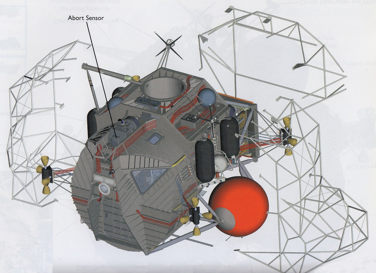
Diagram of installation of the truss frame of the outer hull on the main structure of the take-off stage of the lunar module
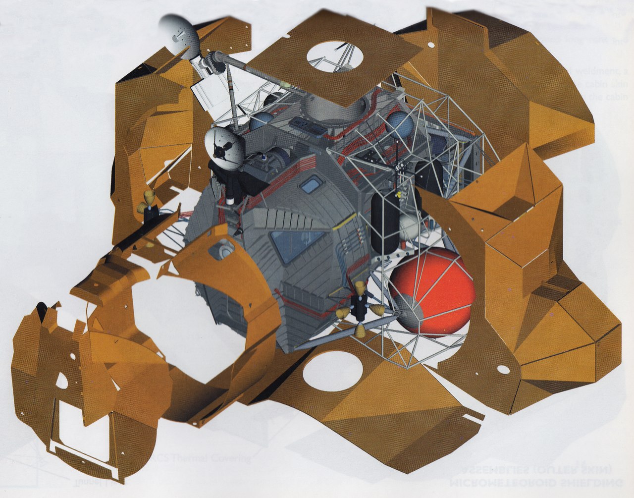
Installation scheme of thermal insulation coating on the main structure of the take-off stage of the lunar module
Micrometeorite protection is an outer shell of the take-off stage of the lunar module and consists of thin sheets of aluminum alloy with a thickness of up to 0.5 mm, installed over the blankets of a thermal insulation coating:
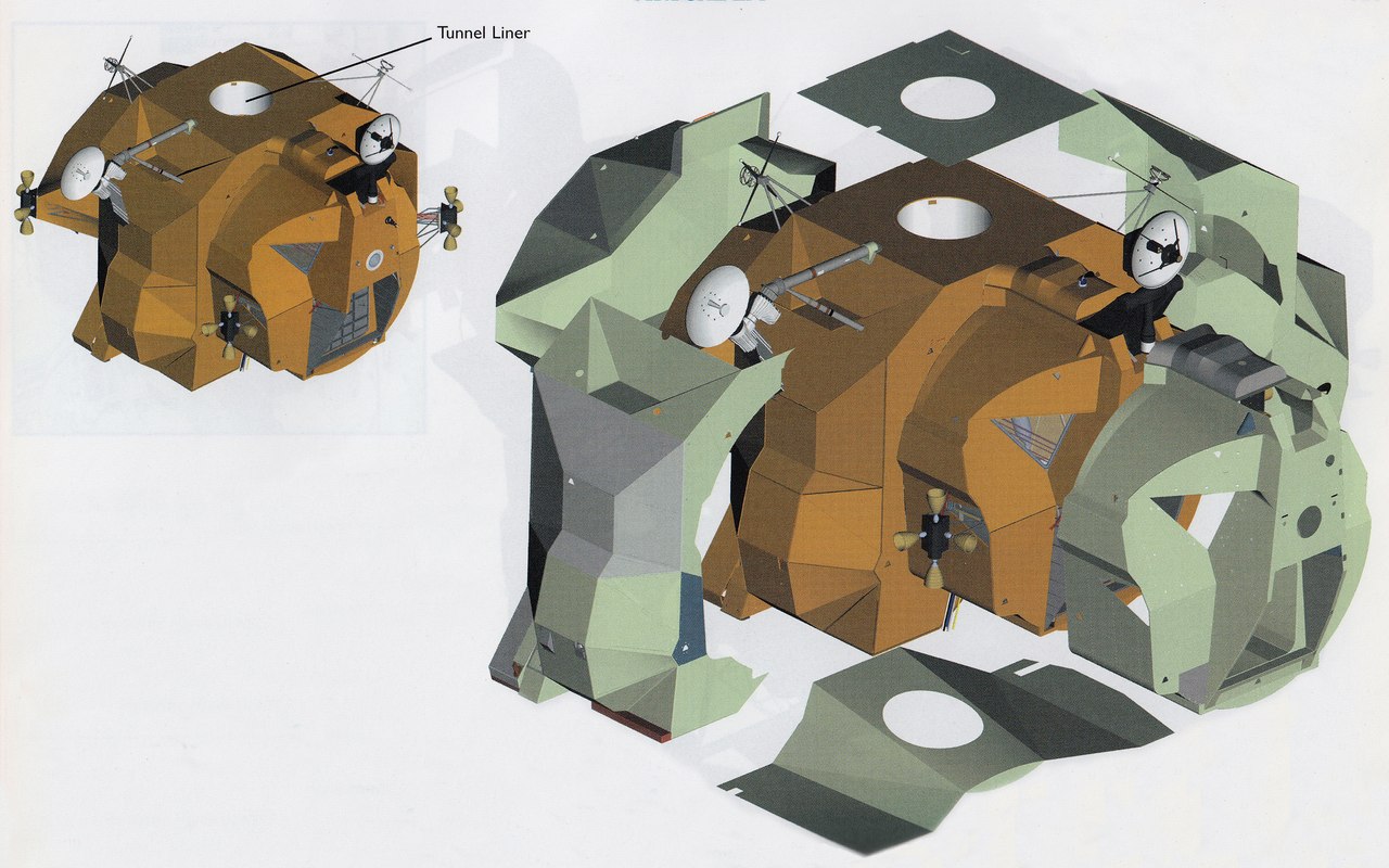
Installation diagram of micrometeorite protection (outer shell) on the thermal insulating coating of the take-off stage of the lunar module
Its cutting by sector is identical. Fastening is carried out using the same special studs, with which a thermal insulation coating is attached to the main structure of the take-off stage of the lunar module. The studs above the blankets have a continuation that provides a minimum gap of 25.4 mm between them and the sheets of protection. The joints between the sheets are taped.
In order to prevent the thermal insulation coating from expanding and micrometeorite protection due to a sharp drop in ambient pressure while booster rocket was set, closed ventilation holes were made in blankets and sheets, through which pressure was equalized.
In the area of impact of the LRE RSU, the micrometeorite protection is covered with a special black thermal paint (it covers most of the micrometeorite protection of the crew cabin).
If you look at the numerous photos of the take-off stage of the lunar module, then the average person gets the impression that the outer shell of thin sheets of aluminum, sometimes glued with adhesive tape, is an airtight sheath that is “easy to punch with your foot,” since it is “made of foil ". This error was clearly demonstrated by Yaroslav Golovanov in a well-known book for space lovers.

PS: Detailed photo report (Walk Around, 57 photos of the take-off stage and 49 photos of the landing stage) on the LTA-1 lunar module can be viewed here.
© Sergey Vyatkin, 2014
* - the studs provide an equal gap between the main structure of the take-off stage of the lunar module, thermal insulation coating and micrometeorite protection.
"R. Schweikart must be very careful. One wrong move, and it will damage the moon cabin. “Its walls are so thin and fragile that a person can punch them with a foot,” said D. McDivitt before the start. “On Earth, the walls of the lunar cabin in many places can damage even the accidentally dropped screwdriver ...”
Another journalist, no less popular popularizer of cosmonautics, Gubarev’s colleague, Yaroslav Kirillovich Golovanov, writes in the well-known book “The Truth about the APOLLO program” (he practically copies his colleague’s text, adding his opinion, which is essentially an amateur’s opinion):
“Schweikart must be very careful,” warned McDivitt. - One wrong move, and it will damage the lunar module. Its walls are so thin and fragile that a person can punch them with their feet. On Earth, the walls of the lunar compartment can damage even the accidentally dropped screwdriver ...
For two weeks I looked at the lunar cabin, which stood in the hall where the press was located during the flight of the Soyuz-19 and Apollo in Houston. "Spider" is made of metal foil. Not from this, of course, in which chocolates are wrapped, but still, if you choose from two definitions: metal sheet or metal foil - foil is more accurate. In vacuum, the rigidity of this structure increased due to internal inflation, but still it remained very subtle. ”( Source )
')
Take-off stage of the lunar module LM-12 of the Apollo 17 spacecraft. Photo of NASA AS17-149-22857
The opinion of Yaroslav Golovanov about the construction “made of foil” and “increasing its rigidity in vacuum” looks especially ridiculous if you look at the photos of the LTA-1 lunar module taken at the Cradle Of Aviation Museum located in the city of East Garden City on Long Island, NY:
LTA-1 (Lunar Test Article 1) is the first copy of the lunar module (prototype), built in 1966, which is structurally similar to serial samples intended for flights into space. Before LTA-1, Grumman Aerospace Corporation built only full-scale mockups of the lunar module (so-called Mock-Up's: M-1, M-5, TM-1). Structurally, these layouts were made of metal and wood, intended for presentation to the customer (NASA), working out layout solutions for the placement of various auxiliary equipment and training of astronauts. But the power structure of the LTA-1, as well as all the systems (propulsion systems, their mixtures, electrical equipment, etc.) were carried out according to working drawings in compliance with all technological processes. This copy was intended for testing the process of manufacturing, assembling and further debugging the lunar module, when design was still underway, as well as for static, dynamic and electrical tests:
Docking of the take-off and landing stages of the LTA-1 lunar module in a conductive electromagnetic interference test room at the Grumman Aerospace Corporation, City of Betpage, Long Island, New York. Photo of NASA S67-22164
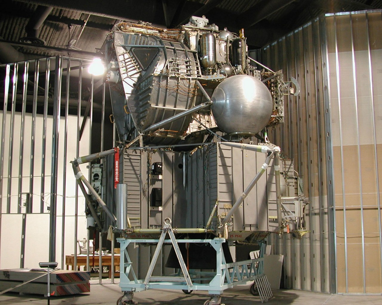
The main design difference of the LTA-1 from the serial samples flying into space is the front hatch, intended for the crew to exit and enter from the take-off stage of the lunar module. On LTA-1 it is round. Starting with LTA-8 and on all serial samples of the lunar module, at the request of astronauts, the hatch was made rectangular. The experiments conducted onboard the NASA “flying laboratory” (reworked Boeing KC-135A Stratotanker tanker) showed that under lunar gravity conditions it was much more convenient for astronauts to squeeze in a spacesuit with a PLSS life support system through a rectangular hatch. In 1974, after the completion of the Apollo program, LTA-1 was deposited with the National Air and Space Museum of the Smithsonian Institution in the city of Washington (DC), and in June 1998 transferred for restoration and further exposure in the Cradle Of Aviation Museum, where it is currently located:
The lunar module of the Apollo spacecraft constructively consists of two stages: the landing and takeoff. The landing stage is equipped with a liquid-propellant rocket engine (LRE) for descending from the orbit of an artificial satellite of the Moon, an approach for landing and soft landing. Landing is carried out on a four-wheel chassis with disc supports. Overloading during landing is reduced due to shortening the legs of the chassis, which are telescopic rods. Kinetic energy when struck on the lunar surface is absorbed by the crumpled filler honeycomb structure of aluminum alloy. The crew, consisting of two astronauts (commander and co-pilot), is located in an airtight cabin of the takeoff stage, which is mounted on top of the landing. Astronauts descend to the surface of the moon is carried out on a ladder mounted on one of the telescopic legs of the landing gear, located on the side of the front hatch. The take-off stage is equipped with a liquid-propellant rocket engine for take-off from the surface (the launching stage at this stage is the landing stage) and an artificial satellite of the Moon entering orbit. Also, the take-off stage is equipped with a reactive control system (DCS). The DCS is designed to control not only the take-off stage, but also the entire lunar module (when it is in a landing configuration) in six degrees of freedom. RSD rocket engines can work in a group or separately - continuously or pulsed. Since the take-off stage accommodates the crew, its design is of the greatest interest within the framework of the mass error under consideration.
The main structure of the take-off stage of the lunar module is a semi-monocoque structure made of a well-welded duralumin alloy 2219 (the main alloying element is copper) and a high-strength deformable aluminum alloy 7075-T6 (the main alloying element is zinc), which have isotropic characteristics. The main structure consists of three main parts: the crew cabin, the central section and the rear equipment compartment:
Only the cockpit and the central section are sealed. These two parts are welded and forged construction, formed by a cylindrical shell and supported by stringers chained around the circumference, formed from sheet duralumin, as well as transverse milled spars to which the elements of the lunar module takeoff stage are attached (beams, connecting brackets, etc.) .). In the cylindrical part of the cockpit above the commander's workplace, an aperture of the docking porthole was made, reinforced around the perimeter. The front of the cockpit is formed by flat milled panels of sheet duralumin, also supported by stringers and spars at the folds. In front of the cockpit are two triangular openings for the front-view windows, reinforced around the perimeter, and between them, below, the opening for the front hatch (round or rectangular).
According to the technical reports on the lunar module ( NTRS archives), the thickness of the walls of the cockpit shell and the central section of the take-off stage of the lunar module reaches 0.065 inches (1.651 mm). This value exceeds the foil thickness by an order of magnitude (in most countries, the commonly accepted definition of foil is sheet metal thickness up to 0.2 mm), and is thicker than the skin of supersonic Tu-144 (1.2 mm) and Concorde (1.5 mm) aircraft, which were operated in more severe conditions than the lunar module: aerodynamic heating when flying at high supersonic speeds in the stratosphere, cyclic stresses in the hermetic fuselage design due to constant pressure drops, aerodynamic effects (bending, twist), etc. . Have been recorded in the operation of Tu-144 and Concorde cases "foot skin penetration."
In some places (unstressed), in order to reduce the weight of the structure, the wall thickness was reduced by chemical milling to 0.012 in. (0.3 mm).
The main structure of the take-off stage of the lunar module is attached to the propulsion system consisting of the Rocketdyne RS-18 rigidly mounted in the central section of the take-off rocket engine (developed on the basis of the Bell 8247 engine), two fuel tanks for it: from the left side of the central section using supporting rod beams a spherical fuel tank (“Aerosin-50”) was installed; a spherical oxidizer tank (nitrogen tetroxide) was similarly installed from the starboard side of the central section.
Rod beams are attached to the rear section of the central section, as well as to the cockpit through brackets, holding four RSU units with sixteen Marquardt R-4D rocket engines (grouped into four engines). Four cylindrical fuel tanks with hemispherical bottoms are located symmetrically on the side of the left and right sides of the central section. Fuel components are similar to those used in the main propulsion system. Spherical helium tanks for the pressure system of these engines are installed on each side between the fuel and oxidizer tanks for the LRE RSU on each side. Two spherical tanks with water and blocks of transmitting antennas are attached to the upper part of the central section.
Displacement gas (helium) for the main propulsion system is also stored in spherical tanks. They are located in the rear compartment of the equipment, along with two helium pressure reduction modules, a control valve for the main propulsion system (controls the supply of fuel components displaced by helium pressure to the take-off LRD RS-18 combustion chamber) and a control valve with cross-control for the LRE RSU. Also in the rear compartment of the equipment above the spherical tanks with helium there are two spherical tanks with gaseous oxygen for the crew’s life support system. On the special remote panel of the rear compartment of the equipment, the blocks of the radio-electronic equipment of the lunar module are installed which are responsible for radio communication, the operation of the on-board systems (alarm, warning) and the blocks of the on-board digital computer (BCM) responsible for navigation. All systems are interconnected by stranded cables and wires running across the entire surface of the main structure of the takeoff stage of the lunar module. Power is supplied by two silver-zinc rechargeable batteries.
To protect the main structure of the lunar module take-off stage and all the systems described above from the effects of space (temperature drops in vacuum, micrometeorites, rocket engine jets), thermal insulation coating and micrometeorite protection are applied, as well as a special thermal protective paint applied to the micrometeorite protection.
Thermal insulation coating is a multi-segment coating of special multi-layered blankets, each segment of which is stretched onto the skeleton of the main structure of the take-off stage. Fastening is carried out using special studs *, which are attached either to special brackets or to a power set (to stringers and side members), ensuring a minimum clearance of 25.4 mm between the inside of the blanket and the outside of the cockpit shell and the central section, as well as the truss structure surrounding the fuel tanks of the main propulsion system and the rear equipment compartment. Each blanket consists of a set of the following layers (if we count from the inside): one layer of aluminized Kapton (DuPont film made of polyamide, thickness 0.5 mm), ten layers of aluminized Mylar (film based on synthetic polyester fiber developed by DuPont, thickness of each layer is 0.15 mm), fifteen layers of aluminized Kapton (thickness of each layer is 0.5 mm). The number of layers of thermal insulation blankets may vary depending on the location of the segment. In the area of impact of the LRE RSU on top of the above layers, an additional thermal insulation coating is applied, consisting of a single layer of nickel foil (thickness 0.5 mm), inconel mesh, and inconel coverage 1.25 mm thick. The blankets are overlapped and held together with special brackets. Joints are sealed with adhesive tapes:
Diagram of installation of the truss frame of the outer hull on the main structure of the take-off stage of the lunar module
Installation scheme of thermal insulation coating on the main structure of the take-off stage of the lunar module
Micrometeorite protection is an outer shell of the take-off stage of the lunar module and consists of thin sheets of aluminum alloy with a thickness of up to 0.5 mm, installed over the blankets of a thermal insulation coating:
Installation diagram of micrometeorite protection (outer shell) on the thermal insulating coating of the take-off stage of the lunar module
Its cutting by sector is identical. Fastening is carried out using the same special studs, with which a thermal insulation coating is attached to the main structure of the take-off stage of the lunar module. The studs above the blankets have a continuation that provides a minimum gap of 25.4 mm between them and the sheets of protection. The joints between the sheets are taped.
In order to prevent the thermal insulation coating from expanding and micrometeorite protection due to a sharp drop in ambient pressure while booster rocket was set, closed ventilation holes were made in blankets and sheets, through which pressure was equalized.
In the area of impact of the LRE RSU, the micrometeorite protection is covered with a special black thermal paint (it covers most of the micrometeorite protection of the crew cabin).
If you look at the numerous photos of the take-off stage of the lunar module, then the average person gets the impression that the outer shell of thin sheets of aluminum, sometimes glued with adhesive tape, is an airtight sheath that is “easy to punch with your foot,” since it is “made of foil ". This error was clearly demonstrated by Yaroslav Golovanov in a well-known book for space lovers.
PS: Detailed photo report (Walk Around, 57 photos of the take-off stage and 49 photos of the landing stage) on the LTA-1 lunar module can be viewed here.
© Sergey Vyatkin, 2014
* - the studs provide an equal gap between the main structure of the take-off stage of the lunar module, thermal insulation coating and micrometeorite protection.
Source: https://habr.com/ru/post/215779/
All Articles