DesignSpark Mechanical: Modeling a useful box for free (that is, for nothing)
Hello, Reader!
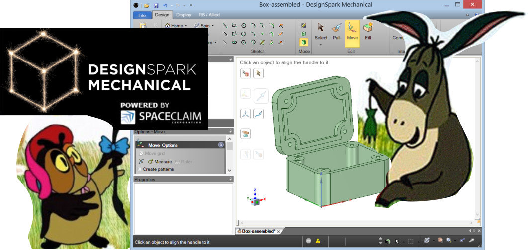
Today, using the free DesignSpark Mechanical package, we will model a useful box with a lid (you can put anything in it!). And since Habr is a technical resource, we will make a box with a lid that is screwed onto four screws (and you can put together any project you like!). The result of our work will be STL files that can be, for example, sent to 3D printing.
')
This article is intended primarily for skillful enthusiasts who, for whatever reason, have not yet begun to work out their ideas, prototypes and products in specialized modeling packages (aka CAD systems).
About a year and a half ago, I realized the huge loss of time that occurs due to the inability to quickly simulate and test concepts arising in my head. The complex mechanical constructions of the Oktodon keyboard, which do not fit in the head, required a rough embodiment “in hardware”. At the incarnation stage, there were changes, adjustments, and the whole process as a whole sometimes resembled swimming in the fog. The solution found by the file was undocumented and poorly reproducible.
At that time, free modeling packages were completely unsuitable for my tasks due to numerous restrictions. Attempts to use them after becoming acquainted with the "heavyweights" caused suffering.
But now times have changed. For a new player entered the field - the free DesignSpark Mechanical (hereinafter referred to as DSM), a stripped-down version of the more powerful SpaceClaim Engineer .
I learned about the release of DesignSpark Mechanical at the end of 2013, as a registered user is also a free design package of printed circuit boards DesignSpark PCB .
One of the distinguishing features of DSM is its focus on creating three-dimensional models of printed circuit boards and housings for electronic devices. On the site www.tracepartsonline.net , the link to which is on the toolbar, you can download three-dimensional models of various components, from resistors to connectors and displays. And just one click on a special button on the toolbar, you can order all the components used in the assembly from the partner site. Here is such an unobtrusive and even sometimes useful commercialization of a free product.
Summary : Using DesignSpark PCB and DesignSpark Mechanical, you can create verified designs of electronic devices - printed circuit boards, components, fasteners, enclosures.
DesignSpark Mechanical is a representative of direct modeling packages.
So, to simulate the desired box, we will use the method of direct modeling.
To begin with, we download the necessary installation package from the manufacturer’s website .
Register and install. We start.
Learning to look around . In order to rotate the camera we hold down the middle mouse button. Adding to this Shift - we shift the camera. Using Ctrl instead of Shift, you can zoom in and out (or you can do it with the mouse wheel). You can switch fixed views, you can save new ones using the buttons of the Orient group on the Design tab panel.
We are finally starting to draw a box . This process is shown in the video, which should be understandable, given that the reader has learned to look around and means that the selection of several objects occurs by holding Ctrl. However, just in case, a detailed description of the action is given under the spoiler.
The following video is about saving work and exporting to a format suitable for 3D printing.
Well that's all.
Hopefully, I managed to convey to you, Reader, the feeling of lightness that arises from the realization of the possibility of everything being measured 7 times before being once-3d-typed.
Thank you for your attention and success in projects!
Today, using the free DesignSpark Mechanical package, we will model a useful box with a lid (you can put anything in it!). And since Habr is a technical resource, we will make a box with a lid that is screwed onto four screws (and you can put together any project you like!). The result of our work will be STL files that can be, for example, sent to 3D printing.
')
This article is intended primarily for skillful enthusiasts who, for whatever reason, have not yet begun to work out their ideas, prototypes and products in specialized modeling packages (aka CAD systems).
Introduction
About a year and a half ago, I realized the huge loss of time that occurs due to the inability to quickly simulate and test concepts arising in my head. The complex mechanical constructions of the Oktodon keyboard, which do not fit in the head, required a rough embodiment “in hardware”. At the incarnation stage, there were changes, adjustments, and the whole process as a whole sometimes resembled swimming in the fog. The solution found by the file was undocumented and poorly reproducible.
Lyrical digression about the choice of CAD system
Even in order to translate thoughts about the design to a designer who would model them on a computer, some kind of metalanguage was needed to explain where it is screwed, what it touches and where it pushes. I used image editors to display concepts. Needless to say that modeling ideas and making changes to them was not at all quick.
In general, at some point, I realized that it is better to spend time and money on the acquisition and development of CAD-systems. Let not at the level of industrial designer, but at the level sufficient for self-verification of concepts.
First, I downloaded trial versions of Autodesk Inventor, SolidEdge ST4, Solid Works, and Alibre Design 2012 (now Geomagic Design) packages and compared them, trying to understand what I needed, which is completely unnecessary, and what can be done without. The issue of price played a very important role, because CAD systems are not cheap at all. Then I made my choice in favor of the Alibre Design 2012 package, which, with Christmas discounts, cost me 25,000 rubles ridiculous for a CAD system (I must say that apart from the price I would choose SolidEdge). So, for reasonable money, I got the opportunity of parametric modeling and work with assemblies. I still use this package. And if there is a demand for information, I can tell you about the pros and cons of this package.
At that time, free modeling packages were completely unsuitable for my tasks due to numerous restrictions. Attempts to use them after becoming acquainted with the "heavyweights" caused suffering.
But now times have changed. For a new player entered the field - the free DesignSpark Mechanical (hereinafter referred to as DSM), a stripped-down version of the more powerful SpaceClaim Engineer .
What is DesignSpark, where did it come from and why is it free?
I learned about the release of DesignSpark Mechanical at the end of 2013, as a registered user is also a free design package of printed circuit boards DesignSpark PCB .
One of the distinguishing features of DSM is its focus on creating three-dimensional models of printed circuit boards and housings for electronic devices. On the site www.tracepartsonline.net , the link to which is on the toolbar, you can download three-dimensional models of various components, from resistors to connectors and displays. And just one click on a special button on the toolbar, you can order all the components used in the assembly from the partner site. Here is such an unobtrusive and even sometimes useful commercialization of a free product.
Summary : Using DesignSpark PCB and DesignSpark Mechanical, you can create verified designs of electronic devices - printed circuit boards, components, fasteners, enclosures.
DesignSpark Mechanical is a representative of direct modeling packages.
Explanation of parametric and direct modeling
There are two main modeling paradigms. Parametric (parametric) and direct (direct). Powerful software packages provide tools for both types of modeling. Especially in this I succeeded warmly likeable to me SolidEdge. What is the difference?
Parametric modeling is the process of sequential modification of the model while preserving the history of modifications. In the parametric approach, you can return to the selected step in the history, change the parameters of the modification applied in this step and apply all subsequent changes.
Direct modeling does not imply the preservation of the history of modifications. Any subsequent action in the simulation is performed on the current state of the model, then where one or another geometry came from, does not play any role. Thus, direct modeling perfectly describes the process of manufacturing a part, apart from the fact that we can not only “cut off” but also “add” material.
In the case when the result is precisely and in advance known, which must be reached, both approaches are close enough. Indeed, there is no point in going back a few steps and changing something, if everything is planned in advance and done as intended.
In reality, both approaches have their advantages. Moreover, for different tasks different approaches can be convenient.
Parametric modeling is akin to programming. Properly created parametric model, as well as a well-written program, allows you to quickly and painlessly experiment with the design, quickly respond to unforeseen circumstances. But the costs are similar: excessive universality at early stages can take an unreasonably long time, and a long search for the desired solution through a series of changes requires further “refactoring” - rebuilding a geometrically equivalent solution in a simpler and more logical way. Some changes in the previous steps, resulting in a qualitative change in the geometry, may make the use of subsequent modifications impossible, or, even worse, erroneous and unpredictable.
Parametric modeling is poorly applicable to modifications of a model whose history of changes is lost, for example, during the export process from an incompatible modeling package. Such models are sometimes called dumb. And direct modeling is exactly what the doctor prescribed in such cases: move this wall, and expand this hole. Such situations with the current diversity of modeling packages are not uncommon.
SpaceClaim is positioning its product as a convenient solution for working with dumb-models.
On top of the picture, direct modeling is easier to learn. And this is very useful.
So, to simulate the desired box, we will use the method of direct modeling.
Model finally
To begin with, we download the necessary installation package from the manufacturer’s website .
Register and install. We start.
Learning to look around . In order to rotate the camera we hold down the middle mouse button. Adding to this Shift - we shift the camera. Using Ctrl instead of Shift, you can zoom in and out (or you can do it with the mouse wheel). You can switch fixed views, you can save new ones using the buttons of the Orient group on the Design tab panel.
We are finally starting to draw a box . This process is shown in the video, which should be understandable, given that the reader has learned to look around and means that the selection of several objects occurs by holding Ctrl. However, just in case, a detailed description of the action is given under the spoiler.
Description of the first video
Select the Rectangle tool in the Sketch group, click at the origin and draw a rectangle. Enter the length and width of the box in millimeters. For example, 80mm to 60mm.
Select the Pull tool of the Edit group and start pulling the rectangle upwards. Enter the height. For example, 40mm.
The box will be with rounded corners. Holding Ctrl select four edges of the future box (it is necessary to make sure that the edges are selected, and not the faces of the parallelepiped).
Using the Pull tool, move the yellow arrow and observe the rounding of the corners. Enter the radius of the rounding. For example, 10mm.
Select the top edge of the box. Focus the camera on it using the Plan View tool.
Using the Circle tool, draw four circles of radius 4 mm in the corners of the box. At the same time DesignSpark helps us to place holes in the center of rounding.
Switch to an isometric view. Select Pull and hold Ctrl. Select the four drawn circles. We make sure that the whole circle stands out and not its circumference. We create holes for the screws, having drawn the selected circles inside the part by 36 mm.
Create a chamfer for screws soak. Select the borders of the holes (this time it is the circle). Use the Pull tool in Chamfer mode to create a 3mm chamfer.
Create a round on the lid: Double-click on the contour of the lid and select the lid border. Use the Pull tool in Round mode to create a rounding radius of 2mm.
Now we divide the part into a cover and a box. To do this, create an auxiliary plane.
Select the top edge of the cover and click the Plane button in the Insert group. This creates a new plane that coincides with the plane of the cover.
Use the Move tool to shift the plane down by 10mm.
Using the Split Body tool, select the box object we created first and then the auxiliary plane. Our object is cut into two objects.
With a triple click, select the top object of the cover and shift it horizontally.
In the Structure tree, rename objects to Box and Cover.
Cut the inside of the box, using the Shell tool of the Insert group to select the top edge of the box. We introduce a wall thickness of 4mm so that the object maintains integrity.
Cut out the inside of the lid with the same tool, but with a thickness of 8mm.
Using the Sketch group's Offset Curve tool, double-click the contour of the inner wall of the lid and expand it by 3.8mm (0.2mm for the best compatibility of the lid with the box.
Select the area between the resulting border and the internal cut-out in the lid and pull the tool Pull by 2 mm. Thus, we get a protrusion positioning the cover on the box with a margin of accuracy of ± 0.2 mm.
For unknown reasons, this operation also generated an extra hanging Surface surface. Remove it.
Put the cover in place. Use the Move tool to select the cover. Pressing the Anchor button in the workspace, select the lower boundary of one of the holes in the lid. After that, pressing the Up To button in the workspace, select the upper boundary of the corresponding hole on the box. The lid becomes exactly in its place.
We tidy up: With the help of the Move to New Component command of the right-click menu in the Structure tree, we declare the cover and box objects as independent components.
Remove unnecessary more plane used for the cut.
We save the project in the native rsdoc format.
The following video is about saving work and exporting to a format suitable for 3D printing.
Description of the second video
After saving the project, both of our components are stored in one file. We take out the components in separate files. To do this, in the right-click menu of the box and lid objects, select Source-> Convert to External. Let's save the project. There are now three files in the project directory. A cover file, a box file and an assembly file containing links to the first two files.
Open the file box. Using the Save As command, we save it in STL format. It can be sent to 3D printing. Profit
Open the file box. Using the Save As command, we save it in STL format. It can be sent to 3D printing. Profit
Well that's all.
Not really
Our model needs a little refinement. For example, now the screw holes have the same diameter 4mm in the lid and in the box. But in order to screw the lid, we need to cut the threads in the holes of the box. This means they will have to narrow down to a diameter of 3.5 mm. Let the Pull tool help you in this task!
Hopefully, I managed to convey to you, Reader, the feeling of lightness that arises from the realization of the possibility of everything being measured 7 times before being once-3d-typed.
Thank you for your attention and success in projects!
Source: https://habr.com/ru/post/215443/
All Articles