Radio-controlled switch do it yourself. Part 4 - Control Center
 Actually, the switch is designed, manufactured , tested , programmed, installed and works quite independently .
Now I would like to use it "to the fullest."
Currently the following remote control options are missing:
- Change the time characteristics of the switch.
- Find out his current status.
- Manage his condition.
The display of the current state and control of the switch is implemented as a web page.
')
Additionally, we implement data storage in a database for further processing (for example, to draw beautiful graphics).
Iron
For further work, I will use:
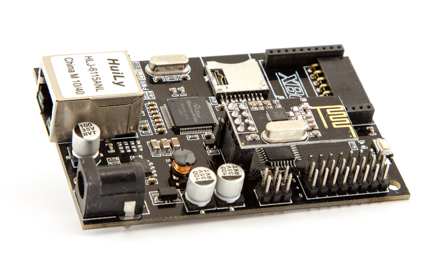
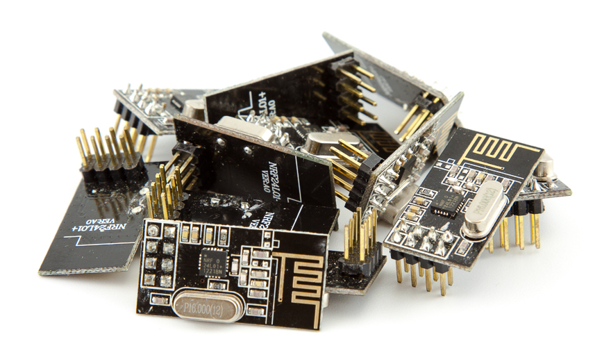
- IBoard board and nrf24l01 + module (from this we organize the LAN gateway <=> RF24)
- Synology NAS (as a web server with a mySQL database)
Naturally, you can use what is at hand (for example, arduinku with Ethernet-shield on Wiznet - to create a gateway) and any computer on which you have php and there is mySQL (we will not do anything super-specific).
Let's see what communication between the modules is obtained.
Distribution of roles
Between the switch (and any other wireless device in my “textbook”) and the gateway — everything is simple and already defined (see the previous article — there is a complete description of the transmitted structure).
Raising a web server on iBoard, which could immediately solve our tasks, is potentially possible, but it is painfully troublesome and, if changes are necessary, you will need to change the code a lot (and if it is located somewhere in a remote place, it is also extremely inconvenient ).
Therefore, we will make of iBoard exactly the gateway that will send the received data to the “big brother” (it is more powerful, therefore, the tasks of logging, displaying information on web pages, etc.) are assigned to it.
The same module will receive “commands” from the “big brother” and send them on the air and report on the responses from the “performers”.
The roles of the “glands” are distributed - now we need to figure out how they will “communicate” with each other.
I think it would be right if:
- Some module reports its status on air, the gateway sends data to the web server (POST method). The server does some checking on the validity of the data and "puts" this data into the database.
- If a request came from the web server (GET method) to the gateway, then the gateway parses the request for the parameters and transmits the request on the air. After that, iBoard receives a response (or does not receive) and generates a response ( JSON ).
It would be possible to send XML to the server as an answer, but you would have to operate with longer lines, which is not very easy to implement on atmega328 modest resources (iBoard is built on this MC).
The principle is described, the case is specific.
Gateway LAN <=> RF24
First, we determine the GET request to the gateway (let it be IP 192.168.1.2). I will use queries of the form:
http://192.168.1.2/?sid=701&cmd=2&pid=1&val=0 The request passes information about which module is being accessed (sid parameter), the command (cmd: 1 - read, 2 - set), the module parameter (pid) and the required value (val).
“Understanding” this command sounds like this: “Switch in the bathroom, turn off the lights” (see previous post ).
The minimum number of parameters that are needed for operation is three (sid, cmd, pid), if there are less parameters, the module must report and report:
{ "message": "Bad request" } If the module "reported" in response to the request, the gateway should issue a response:
{"message": "OK","sensor": 701,"parameter": {"pid": 1,"pval": 0.000,"st": 1,"note": "Ch.1 (Light)"}} The answer contains complete information about the corresponding parameter (and the answer is as close as possible to the structure used in the radio exchange).
If the answer is not received:
{ "message": "No answer" } Now it seems that the gateway somehow got a few tasks, so we’ll "load up" a little with its function of obtaining the exact time via NTP.
Those. Our gateway also becomes a “sensor” with two parameters - “date” and “time”. I have already described how to do this before (see Wireless communications of the “smart home”. Part two, practical ).
Again, do not forget about the "guard dog" for this very important component of our system.
When all the functions of the system are described, it remains to be a matter of technique to write the appropriate sketch .
We are flashing iBoard, connecting a LAN cable, supplying power, and if everything is in order, it is already possible to receive the status and control of the wireless module via GET requests, i.e. Some of the tasks have already been partially solved, but it is still not very convenient (we will fix this soon).
The gateway is better located in the center (apartments, houses), so that the distance to all wireless modules would be minimal.
You can proceed to the server side.
We believe that your server has already been prepared: the web server with PHP and mySQL is working.
Disclaimer : the code is very far from ideal and is provided solely in order to demonstrate the basic principles.
Proof of concept - no more than that. If you use it in this form - only at your own peril and risk.
Server
For definiteness, the server has an ip-address of 192.168.1.10. This address appears in the sketch above, in the same place there is the address of the page that should receive data from the gateway: 192.168.1.10/sensors - we will start from this page.
Database
But before starting to develop the page - let's prepare the database. The easiest way is to do this via phpMyAdmin.
My database is called db_sensors and contains only two tables: sensor_list and sensor_value (the assignment of tables is perfectly guessed from their names).
Script to create tables
-- -- `sensor_list` -- CREATE TABLE IF NOT EXISTS `sensor_list` ( `id` int(11) NOT NULL AUTO_INCREMENT, `name` varchar(16) CHARACTER SET utf8 COLLATE utf8_unicode_ci NOT NULL, `unit` varchar(16) CHARACTER SET utf8 COLLATE utf8_unicode_ci DEFAULT NULL, `comment` varchar(100) CHARACTER SET utf8 COLLATE utf8_unicode_ci DEFAULT NULL, `SensorID` int(11) NOT NULL, `ParamID` int(11) NOT NULL, `created` timestamp NOT NULL DEFAULT CURRENT_TIMESTAMP, `value` float NOT NULL COMMENT ' ', `last` datetime NOT NULL COMMENT ' ', PRIMARY KEY (`id`) ) ; -- -------------------------------------------------------- -- -- `sensor_value` -- CREATE TABLE IF NOT EXISTS `sensor_value` ( `id` bigint(11) NOT NULL AUTO_INCREMENT, `sensor_id` int(11) NOT NULL, `value` float NOT NULL, `created` timestamp NOT NULL DEFAULT CURRENT_TIMESTAMP, PRIMARY KEY (`id`) ) ; The base is ready, we create a page that would accept the data and save it to the base.
Data logging
To make it easier to debug - we will make this page in the form of a form that posts the data to itself and checks them for validity.
Additionally, we will enter the correct key in the list of mandatory data of the request (which is explicitly specified in the gateway sketch) in order to accept requests only from “our own”. It is clear that everything is not too safe, but on the basis of disclaimer, it is quite acceptable.
The logic of the script is as follows:
- Primary check for all the necessary parameters and check the validity of the key.
- Check if there is an entry in the sensor_list table about such a “sensor”. If there is no such record, we create it and get the record identifier; otherwise, we get the identifier already existing.
- Write to the table sensor_value the corresponding value of the "sensor".
- Additionally, we update the last value of the corresponding sensor in the sensor_list table and fix the time of the last contact.
The latter was done so that the last value could be quickly obtained (sampling on the first table is much faster) and it was possible to quickly assess how relevant this data is.
By the way, a sample from this table with actual data is conveniently used as data for Universal Widget (it’s a pity that the project hasn’t been updated for a very long time).
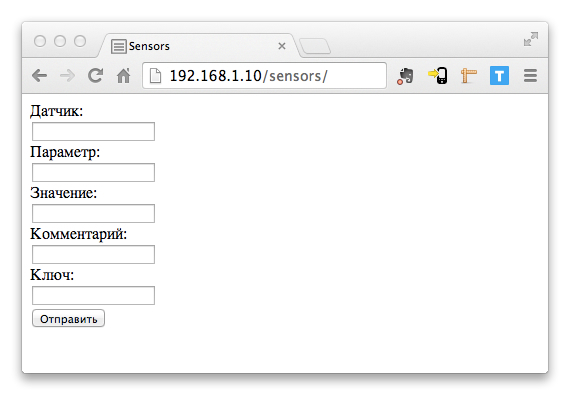
The script was prepared, the file was called index.php, placed in the \ sensors \ folder (relative to the site root).
An archive with all web server files is available here .
Now you can contact him at the address: 192.168.1.10/sensors
If everything is done correctly, then a form will open at this address into which you can insert test values into your hands and check (via phpMyAdmin, for example) that the data is checked and correctly placed in the database.
If you already have a radio switch and a gateway, this data will also be sent to the database.
The task of logging was decided; now we will implement a more convenient way of reading and changing the parameters of wireless modules.
Reading and modifying module parameters
Let's create another script (at 192.168.1.10/tests ), which of itself will also represent the form with which the server will form requests to our gateway, receive responses and display them in the same form.
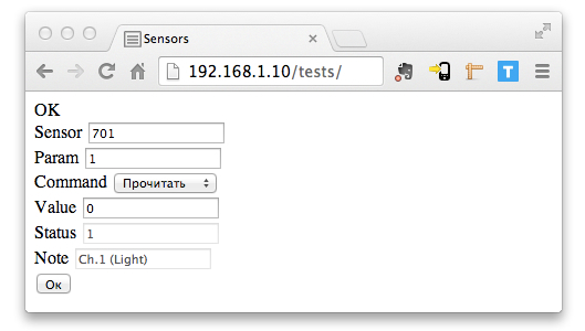
In the image above, the result of the form is already being processed: the two upper fields and the selector form the data for the request, “OK” is the value of the message parameter from the response, the remaining parameters are the corresponding parts of the response.
Parsing the answer is done using JavaScript.
In the work of this script there is a little trick. These forms are not sent immediately to the gateway, but pass through the json-proxy.php file
This approach allows you to access the "main" script from the external network, while the gateway can remain in the internal network.
In this intermediate file, you should do a full data check in order to protect yourself from SQL injection.
It is much more convenient to work with this page, but again, so far everything is at the level of one parameter of a specific sensor.
Control Center Home
Now you can combine our achievements, read a little about AJAX and make just such a page (at 192.168.1.10/tests/switch.php ):
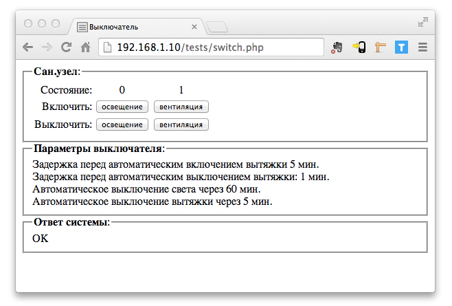
To update the data of a specific parameter, the function chekIt (701, 1, 'ch1') is called; (actually, there are three arguments: the module number, the parameter number, and the identifier of the div, the contents of which need to be updated).
The page displays the time parameters of the module operation (in order not to strain our gateway, which is weak in resources) - we request this data every 5 minutes.
Data on the status of the lighting and ventilation channels is updated more often - once every 5 seconds (often enough so that you do not have to wait long for the state to change after pressing the corresponding on or off button).
The doIt () function calls are “hung” on buttons:
<input type="button" value="" onclick="doIt(701,1,1);"> Function parameters: module number, parameter number and new value.
At the very bottom of the page, the gateway response is displayed.
The data on the page is displayed without rebooting, everything happens “by itself”.
Result
- Now the radio-controlled switch works not only by itself, but is also conveniently controlled from a web page.
- A universal gateway LAN <=> RF24 was created, which allows working with various home wireless devices. Simply add a new device with the same radio protocol - no changes are required in the gateway code.
- Configured constant logging of sensor values for post-processing (for example, for analyzing or building beautiful graphs).
Further development of the project
On the server, you can organize any additional data processing, which will allow to implement various scenarios.
For example: a long press on the on / off button of the lighting of our radio-controlled switch (remember, one of the module's parameters is set to “1”) will launch the script, which will turn off all switched on light sources (of course, they must also be equipped with radio-controlled switches).
This completes my “teaching material” on this topic. Thank you for your attention and sorry that the "course" was so prolonged.
Thank you Nikita_Rogatnev for help in preparing the material for publication.
Source: https://habr.com/ru/post/215419/
All Articles