Channel aggregation and IP traffic balancing for storage
For small companies, only two or four servers with virtualization are often used, two Ethernet switches, sometimes even with stacking capability, and Multi-chassis EtherChannel plus lower-end storage systems — this is quite a standard configuration of medium business infrastructure.
It is very important for such enterprises to maximize the use of all available technologies in order to utilize their equipment as much as possible and this article will discuss how to achieve this.
Most modern servers on board usually have at least two 1Gb interfaces for data and one 100Mb for management.
On the storage system of the younger NetApp FAS 2240 / FAS 2220 series, on board each controller, among other things, there is a 4x 1Gb port.
Those. It is quite logical to use a scheme where two switches in a stack use Multi-chassis EtherChannel aggregating links from each controller to each switch to obtain both fault tolerance and utilization of throughput of all these links. Such is the architecture in the image and likeness of FlexPod Express , but without the fashionably-expensive vPC features like Cisco switches of the Nexus series, in this case, instead of interlinks, the stack of switches will be used. And generally servers and switches in such a scheme can be of any manufacturer. And if everything is quite tight with the budget, you can use the direct connection to the server, so if the server has 2 ports on board, you can connect 4 servers, and when you need to add the 5th server, then you will have to buy switches.
')
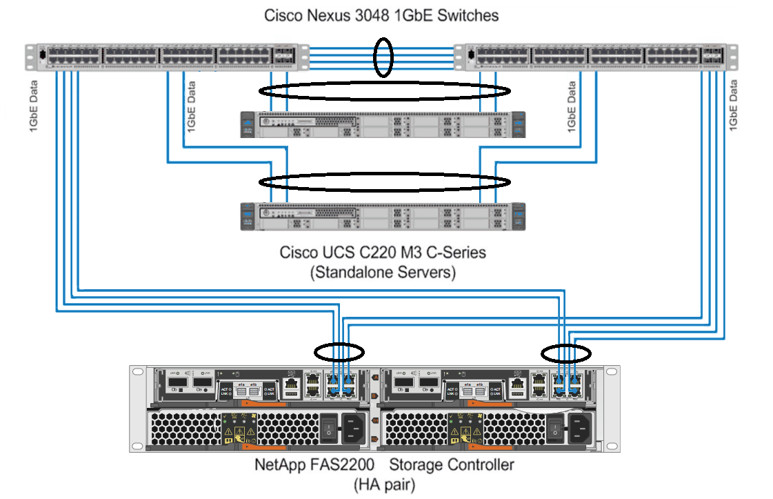
Connection diagram FlexPod Express.
Here is an example of the scheme, which will be described in the article.
FAS 2240-4 HA - 2 controllers with 4 1 Gbps link
2 servers with VMware ESXi, each with 4 dedicated network ports of 1 GB for communication with the storage
2 gigabit stack switches with Multi-chassis EtherChannel and LACP support
So, we want to use all available bandwidth and available server and storage interfaces. Those. Server 1 works mainly with VMs located on controller A, server 2 with VMs on controller B, all have 4 interfaces, the VMs are divided into 4 groups, everything is divided evenly and honestly.
But load balancing in the network “magically” cannot smear this load across all the links itself. There is an algorithm that allows you to alternately use one of the links in the aggregated channel. One of these algorithms is based on the hash sums of the source and destination IP addresses received from the headers, choosing one link . And this nuance plays an important role in our scheme. Since if the hash sum for two different IP source and recipient combinations coincide, the same physical link will be used for such combinations. In other words, it is important to understand how the algorithm for balancing network traffic works and to ensure that the combination of IP addresses is such as to obtain a fault-tolerant infrastructure scheme and use all network links, relying on best practices from NetApp TR - 3749 , TR - 3802 and TR - 3839 .
As a rule, 2-4 servers do not load 1Gb bandwidth links, the use of all links at the same time has a positive effect on the speed of interaction between network nodes and bandwidth at peak loads.
Further (for simplicity), manipulations with one controller, one server and NFS protocol are described.
We need to:
NetApp FAS storage configuration snippets :
Note that the " lacp " parameter in the " ifgrp create lacp vif1 -b ip e0d e0b e0c e0a " line corresponds to the Dynamic Multi-Mode in the documentation and must match the settings on the switch . TR - 3802
Also, do not forget about the correct settings of the flowcontrol from both the storage and the switch. If the storage “sends” ( flowcontrol send ) flow control, then “on the other side” the switch must be configured to “receive” flow control ( flowcontrol receive on ). And vice versa: if no one sends, then no one should be set up for acceptance. More about flowcontrol .
Let me remind you that two controllers work in a fault-tolerant pair, and if one controller “dies”, it will “overeat” (in terms of NetApp FailOver) the second controller and two logical ones will work on the physical controller. On the part of the host, it is very important to set a timeout for the case of such a move of 90 seconds. Pay attention to the record partner vif1-53 , it means that in the case of FailOver when moving to the second controller, the settings of this virtual interface will also be moved with it. For this reason, do not forget to specify this entry, otherwise the controller will overeat, and the data available at the old addresses will not be available. The general logic of assigning a partner to an interface is as follows:
And do not forget to make the same VIF and VLAN settings on the second controller, so that it is “what” to move. On the side of the switches on the ports from the first controller, we allow the circulation of those VLANs that the neighbor has so that there is connectivity in case of a move.
Also note that the NetApp FAS storage system uses interface numbering for balancing in the VIF, not in alphabetical order, but in the order of addition.
For example, if a VIF is created with such a command “ifgrp create lacp vif1 -b ip e0d e0b e0c e0a”, then e0d will be the 0th interface, e0b - 1, e0c - 2, e0a - 3.
The following datastores are connected to VMware ESXi
After configuration, we give the load from the test VMs and check the load on the ports from the storage controller:
So you can see that the traffic is almost not sent over the e0a interface (Pkts Out column).
We go to the side of the switch (the switch averages data for a period of several minutes, because the utilization is only 80%, not almost 100%) and we see that the Ethernet port 1/11 practically does not accept frames.
Visible load (Rx) for the controller in the “Rx Util” column and load for transmission (Tx) for the server in the “Tx Util” column. It can be seen that 2 datastores share one controller link.
When you start the generation of linear recording on all 4 VM and 4 NFS balls respectively, balancing the traffic does not depend on the storage system , so the picture is expected.
It turns out that the storage system for aggregation of channels with IP balancing does not use all the available lines, as it should be according to theory, but only 3 out of 4. At the same time, all other participants (switch and ESXi) balance correctly across all 4 lines. The traffic of 2 datastores from the storage system to the switch goes in one link, and from the switch to ESXi, already in two.
A similar picture is observed when working under the iSCSI protocol. One of the 4 links to the outgoing communication DSS is practically not loaded (5-10 packets in 10 seconds). On the second controller and another server, the situation is similar.
Why is this happening? Yes, because the hash of the sum of the two IP pairs coincide, forcing the algorithm to choose the same link. In other words, you just need to pick up other IP.
You can simply go through the IP options. In writing the program for selecting IP addresses, the great difficulty lies in the fact that the algorithm uses bitwise shifts over the significant 32bit integer and addition operations over them (overflows are discarded). Since the scripting languages are now weakly focused on the fixed bitness of numbers, it was not possible to achieve a normal calculation in python. Therefore, a small program for the calculation of the entire range was written in C, and then use the results in the enumeration.
Starting with Data ONTAP 7.3.2, not just a XOR operation over the two source and destination IP addresses is used to select a path ((source_address XOR destination_address)% number_of_links) . A more complex bit-wise algorithm called SuperFastHash is a more dynamic, more balanced way to distribute the load and provides better balancing for a large number of customers. The result is almost the same, but each TCP session is associated with only one interface.
By the way, to quickly get the result is very convenient to use the online compiler .
Below are the options for choosing the IP addresses of the storage , provided that there are 3 servers (with IP addresses ending in 21, 22 and 23 and the number of interfaces to the storage system of 3, 4 and 4, respectively).
The calculation was made for two networks XX.YY.52.ZZ / 24 and XX.YY.53.ZZ / 24. IP addresses for storage systems that meet the above conditions were selected.
When exchanging traffic between a server with IP XX.YY.52.22 and storage alias XX.YY.52.35, traffic:
from storage to switch (column NetApp Out, 22) goes through interface number 2 by numbering the storage from switch to storage (column NetApp In, 22) goes through interface number 1 using switch numbering from switch to server and from server to switch ( Server InOut column, 22) will go on port 1 in the server numbering and switch, respectively (not the fact that they consider the same)
It can be seen that for each server traffic with different aliases on one controller will go through different interfaces. Similarly, traffic from different servers to one IP storage system will go through different interfaces.

, IP NetApp .
++ .
.
It is very important for such enterprises to maximize the use of all available technologies in order to utilize their equipment as much as possible and this article will discuss how to achieve this.
Most modern servers on board usually have at least two 1Gb interfaces for data and one 100Mb for management.
On the storage system of the younger NetApp FAS 2240 / FAS 2220 series, on board each controller, among other things, there is a 4x 1Gb port.
Those. It is quite logical to use a scheme where two switches in a stack use Multi-chassis EtherChannel aggregating links from each controller to each switch to obtain both fault tolerance and utilization of throughput of all these links. Such is the architecture in the image and likeness of FlexPod Express , but without the fashionably-expensive vPC features like Cisco switches of the Nexus series, in this case, instead of interlinks, the stack of switches will be used. And generally servers and switches in such a scheme can be of any manufacturer. And if everything is quite tight with the budget, you can use the direct connection to the server, so if the server has 2 ports on board, you can connect 4 servers, and when you need to add the 5th server, then you will have to buy switches.
')
Connection diagram FlexPod Express.
Here is an example of the scheme, which will be described in the article.
FAS 2240-4 HA - 2 controllers with 4 1 Gbps link
2 servers with VMware ESXi, each with 4 dedicated network ports of 1 GB for communication with the storage
2 gigabit stack switches with Multi-chassis EtherChannel and LACP support
So, we want to use all available bandwidth and available server and storage interfaces. Those. Server 1 works mainly with VMs located on controller A, server 2 with VMs on controller B, all have 4 interfaces, the VMs are divided into 4 groups, everything is divided evenly and honestly.
Theoretical part
But load balancing in the network “magically” cannot smear this load across all the links itself. There is an algorithm that allows you to alternately use one of the links in the aggregated channel. One of these algorithms is based on the hash sums of the source and destination IP addresses received from the headers, choosing one link . And this nuance plays an important role in our scheme. Since if the hash sum for two different IP source and recipient combinations coincide, the same physical link will be used for such combinations. In other words, it is important to understand how the algorithm for balancing network traffic works and to ensure that the combination of IP addresses is such as to obtain a fault-tolerant infrastructure scheme and use all network links, relying on best practices from NetApp TR - 3749 , TR - 3802 and TR - 3839 .
As a rule, 2-4 servers do not load 1Gb bandwidth links, the use of all links at the same time has a positive effect on the speed of interaction between network nodes and bandwidth at peak loads.
Description
Further (for simplicity), manipulations with one controller, one server and NFS protocol are described.
- 2 controller links are connected to one switch, 2 to another
- on the side of the switch multichassis LACP is configured with IP balancing
- the switch for the controller ports is set to Flowcontrol = on
- on the controller for all ports, Flowcontrol = send is installed
- 4 1GB links on the controller side combined into one LACP with IP balancing
- over VIF (ifgrp), a VLAN was created and assigned an IP, 3 additional aliases were created (addresses are issued sequentially)
- 4 volumes created, qtree created in each volume, volume exported via NFS
- ESXi server has vSwitch with 4 interfaces with IP balancing
- on this vSwitch , a vmkernel port is created in the same IP subnet and the same VLAN in which the primary IP and controller aliases are located
- jumbo frames included in the whole chain ( storage , switch, switch VLAN , vSwitch , vmkernel port)
- 4 NFS datastores added to ESXi, all from different IP addresses (i.e., both the main IP and all the controller aliases are involved)
- 4 VM vmware-io-analyzer.ova on different NFS datastores to check the load on links using, for example, the Max-throughput pattern
We need to:
- one NFS export was connected to all vmware ESXi hosts at the same IP address so that vmware perceived it as one datastorage and not as different (there is no such requirement for iSCSI ; for each server you can specify different IP targets , IQN will have the same )
- traffic (inbound and outbound) from one server to different datastorage should go on different server and storage links
- traffic (inbound and outbound) from different servers to the same datastorage should go on different storage links
Customization
NetApp FAS storage configuration snippets :
Note that the " lacp " parameter in the " ifgrp create lacp vif1 -b ip e0d e0b e0c e0a " line corresponds to the Dynamic Multi-Mode in the documentation and must match the settings on the switch . TR - 3802
Also, do not forget about the correct settings of the flowcontrol from both the storage and the switch. If the storage “sends” ( flowcontrol send ) flow control, then “on the other side” the switch must be configured to “receive” flow control ( flowcontrol receive on ). And vice versa: if no one sends, then no one should be set up for acceptance. More about flowcontrol .
NetApp 7-Mode Setup Example
san01a> rdfile /etc/rc #Auto-generated by setup Thu may 22 13:26:59 GMT 2014 hostname san01a ifgrp create lacp vif1 -b ip e0d e0b e0c e0a vlan create vif1 53 ifconfig e0a flowcontrol send up ifconfig e0b flowcontrol send up ifconfig e0c flowcontrol send up ifconfig e0d flowcontrol send up ifconfig e0M `hostname`-e0M netmask 255.255.255.0 broadcast 10.10.10.255 flowcontrol full partner 10.10.40.11 mtusize 1500 trusted wins up ifconfig e0P `hostname`-e0P netmask 255.255.252.0 broadcast 192.168.3.255 flowcontrol full up ifconfig vif1-53 `hostname`-vif1-53 netmask 255.255.255.0 partner vif1-53 mtusize 9000 trusted -wins up ifconfig vif1-53 alias 10.10.53.31 netmask 255.255.255.0 up ifconfig vif1-53 alias 10.10.53.32 netmask 255.255.255.0 up ifconfig vif1-53 alias 10.10.53.33 netmask 255.255.255.0 up route add net default 10.10.10.3 1 routed on options dns.domainname netapp.com options dns.enable on options nis.enable off savecore Fault tolerance for NFS
Let me remind you that two controllers work in a fault-tolerant pair, and if one controller “dies”, it will “overeat” (in terms of NetApp FailOver) the second controller and two logical ones will work on the physical controller. On the part of the host, it is very important to set a timeout for the case of such a move of 90 seconds. Pay attention to the record partner vif1-53 , it means that in the case of FailOver when moving to the second controller, the settings of this virtual interface will also be moved with it. For this reason, do not forget to specify this entry, otherwise the controller will overeat, and the data available at the old addresses will not be available. The general logic of assigning a partner to an interface is as follows:
- If there is a Tim-Interface (s) ( VIF ) with VLAN (s), then configure each such VLAN 'e.
- If there are VIF (s), but without VLAN (s), then configure it on each such VIF interface.
- If there is no VIF , but there are VLAN (s) on the physical interface, then we configure on each such VLAN 'e.
- If there is no VIF or VLAN (s) anywhere, then on each physical interface.
And do not forget to make the same VIF and VLAN settings on the second controller, so that it is “what” to move. On the side of the switches on the ports from the first controller, we allow the circulation of those VLANs that the neighbor has so that there is connectivity in case of a move.
Also note that the NetApp FAS storage system uses interface numbering for balancing in the VIF, not in alphabetical order, but in the order of addition.
For example, if a VIF is created with such a command “ifgrp create lacp vif1 -b ip e0d e0b e0c e0a”, then e0d will be the 0th interface, e0b - 1, e0c - 2, e0a - 3.
Example of setting rezolv, export and Qtree for netApp 7-Mode
san01a> rdfile /etc/hosts #Auto-generated by setup Thu may 22 13:26:59 GMT 2014 127.0.0.1 localhost localhost-stack 127.0.10.1 localhost-10 localhost-bsd 127.0.20.1 localhost-20 localhost-sk 10.10.40.10 san01a san01a-e0M 192.168.1.185 san01a san01a-e0P 10.10.53.30 san01a-vif1-53 san01a> exportfs /vol/vol_filerA_nfsA -sec=sys,rw,nosuid /vol/vol_filerA_nfsB -sec=sys,rw,nosuid /vol/vol_filerA_nfsC -sec=sys,rw,nosuid /vol/vol_filerA_nfsD -sec=sys,rw,nosuid san01a> qtree status Volume Tree Style Oplocks Status -------- -------- ----- -------- --------- rootvol unix enabled normal vol_filerA_nfsA unix enabled normal vol_filerA_nfsA qtree_filerA_nfsA unix enabled normal vol_filerA_nfsB unix enabled normal vol_filerA_nfsB qtree_filerA_nfsB unix enabled normal vol_filerA_nfsC unix enabled normal vol_filerA_nfsC qtree_filerA_nfsC unix enabled normal vol_filerA_nfsD unix enabled normal vol_filerA_nfsD qtree_filerA_nfsD unix enabled normal The following datastores are connected to VMware ESXi
ds_filerA_nfsA 10.10.53.30:/vol/vol_filerA_nfsA/qtree_filerA_nfsA ds_filerA_nfsB 10.10.53.31:/vol/vol_filerA_nfsB/qtree_filerA_nfsB ds_filerA_nfsC 10.10.53.32:/vol/vol_filerA_nfsC/qtree_filerA_nfsC ds_filerA_nfsD 10.10.53.33:/vol/vol_filerA_nfsD/qtree_filerA_nfsD After configuration, we give the load from the test VMs and check the load on the ports from the storage controller:
We check the load on the ports of NetApp in 7-Mode
san01a> ifgrp stat vif1 10 Interface group(trunk) vif1 e0b e0a e0c e0d Pkts In Pkts Out Pkts In Pkts Out Pkts In Pkts Out Pkts In Pkts Out 14225k 13673k 15542k 249k 13838k 11690k 15544k 7809k 46075 38052 90911 7 45882 37666 90812 37704 46953 37735 91581 4 46506 37613 91777 37625 46822 38016 91409 7 45498 37589 91670 37687 46906 38046 91514 6 45469 37591 91495 37588 46600 37737 91308 4 46554 37538 91514 37610 46792 37929 91371 7 45803 37532 91261 37508 46845 37831 91228 8 46307 37517 91450 37587 So you can see that the traffic is almost not sent over the e0a interface (Pkts Out column).
Detailed output on the ports of the storage controller
san01a> ifstat -a -- interface e0a (3 hours, 30 minutes, 53 seconds) -- RECEIVE Frames/second: 9147 | Bytes/second: 916k | Errors/minute: 0 Discards/minute: 0 | Total frames: 16347k | Total bytes: 73753m Total errors: 0 | Total discards: 0 | Multi/broadcast: 0 No buffers: 0 | Non-primary u/c: 0 | Tag drop: 0 Vlan tag drop: 0 | Vlan untag drop: 0 | Vlan forwards: 0 Vlan broadcasts: 0 | Vlan unicasts: 0 | CRC errors: 0 Runt frames: 0 | Fragment: 0 | Long frames: 0 Jabber: 0 | Alignment errors: 0 | Bus overruns: 0 Xon: 0 | Xoff: 0 | Jumbo: 8359k TRANSMIT Frames/second: 1 | Bytes/second: 87 | Errors/minute: 0 Discards/minute: 0 | Total frames: 249k | Total bytes: 7674m Total errors: 0 | Total discards: 0 | Multi/broadcast: 1006 Queue overflows: 0 | No buffers: 0 | Max collisions: 0 Single collision: 0 | Multi collisions: 0 | Late collisions: 0 Xon: 0 | Xoff: 0 | Jumbo: 239k LINK_INFO Current state: up | Up to downs: 2 | Speed: 1000m Duplex: full | Flowcontrol: none -- interface e0b (3 hours, 30 minutes, 53 seconds) -- RECEIVE Frames/second: 4678 | Bytes/second: 467k | Errors/minute: 0 Discards/minute: 0 | Total frames: 14637k | Total bytes: 73533m Total errors: 0 | Total discards: 0 | Multi/broadcast: 0 No buffers: 0 | Non-primary u/c: 0 | Tag drop: 0 Vlan tag drop: 0 | Vlan untag drop: 0 | Vlan forwards: 0 Vlan broadcasts: 0 | Vlan unicasts: 0 | CRC errors: 0 Runt frames: 0 | Fragment: 0 | Long frames: 0 Jabber: 0 | Alignment errors: 0 | Bus overruns: 0 Xon: 0 | Xoff: 0 | Jumbo: 8352k TRANSMIT Frames/second: 3773 | Bytes/second: 123m | Errors/minute: 0 Discards/minute: 0 | Total frames: 14007k | Total bytes: 57209m Total errors: 0 | Total discards: 1 | Multi/broadcast: 1531 Queue overflows: 1 | No buffers: 0 | Max collisions: 0 Single collision: 0 | Multi collisions: 0 | Late collisions: 0 Xon: 0 | Xoff: 0 | Jumbo: 2756k LINK_INFO Current state: up | Up to downs: 2 | Speed: 1000m Duplex: full | Flowcontrol: none -- interface e0c (3 hours, 30 minutes, 53 seconds) -- RECEIVE Frames/second: 4630 | Bytes/second: 461k | Errors/minute: 0 Discards/minute: 0 | Total frames: 14243k | Total bytes: 69574m Total errors: 0 | Total discards: 0 | Multi/broadcast: 0 No buffers: 0 | Non-primary u/c: 0 | Tag drop: 0 Vlan tag drop: 0 | Vlan untag drop: 0 | Vlan forwards: 0 Vlan broadcasts: 0 | Vlan unicasts: 0 | CRC errors: 0 Runt frames: 0 | Fragment: 0 | Long frames: 0 Jabber: 0 | Alignment errors: 0 | Bus overruns: 0 Xon: 0 | Xoff: 0 | Jumbo: 7800k TRANSMIT Frames/second: 3756 | Bytes/second: 123m | Errors/minute: 0 Discards/minute: 0 | Total frames: 12022k | Total bytes: 189g Total errors: 0 | Total discards: 0 | Multi/broadcast: 1003 Queue overflows: 0 | No buffers: 0 | Max collisions: 0 Single collision: 0 | Multi collisions: 0 | Late collisions: 0 Xon: 0 | Xoff: 0 | Jumbo: 6283k LINK_INFO Current state: up | Up to downs: 2 | Speed: 1000m Duplex: full | Flowcontrol: none -- interface e0d (3 hours, 30 minutes, 53 seconds) -- RECEIVE Frames/second: 9127 | Bytes/second: 915k | Errors/minute: 0 Discards/minute: 0 | Total frames: 16349k | Total bytes: 73554m Total errors: 0 | Total discards: 0 | Multi/broadcast: 0 No buffers: 0 | Non-primary u/c: 0 | Tag drop: 0 Vlan tag drop: 0 | Vlan untag drop: 0 | Vlan forwards: 0 Vlan broadcasts: 0 | Vlan unicasts: 0 | CRC errors: 0 Runt frames: 0 | Fragment: 0 | Long frames: 0 Jabber: 0 | Alignment errors: 0 | Bus overruns: 0 Xon: 0 | Xoff: 0 | Jumbo: 8339k TRANSMIT Frames/second: 3748 | Bytes/second: 123m | Errors/minute: 0 Discards/minute: 0 | Total frames: 8140k | Total bytes: 62385m Total errors: 0 | Total discards: 0 | Multi/broadcast: 1213 Queue overflows: 0 | No buffers: 0 | Max collisions: 0 Single collision: 0 | Multi collisions: 0 | Late collisions: 0 Xon: 0 | Xoff: 0 | Jumbo: 2413k LINK_INFO Current state: up | Up to downs: 2 | Speed: 1000m Duplex: full | Flowcontrol: none Switch
We go to the side of the switch (the switch averages data for a period of several minutes, because the utilization is only 80%, not almost 100%) and we see that the Ethernet port 1/11 practically does not accept frames.
Example of configuring two Cisco Catalyst 3850s in a stack through 1GBE ports
Note the " mode active " ( LACP ) in the interface configuration of the line channel-group 1 mode active . Mode active ( LACP ) corresponds to Dynamic Multi-Mode on NetApp. For details, see TR - 3802 .
Also note the " flowcontrol receive on ", the setting of this parameter can vary and depends on several parameters: port speed and switch type. If the storage “sends” ( flowcontrol send ) messages about flow control, then “on the other side” the switch must be configured to “receive” flow control ( flowcontrol receive on ). More about flowcontrol .
And do not forget about the recommendations for setting up Spanning-Tree , where it is desirable to enable RSTP or the proprietary Rapid-PVST + and set the switch ports connected to the end nodes in the spanning-tree portfast state .
NetApp FAS systems support CDP , you can turn it on or leave it off.
system mtu 9198 ! spanning-tree mode rapid-pvst ! interface Port-channel1 description N1A-1G-e0a-e0b switchport trunk native vlan 1 switchport trunk allowed vlan 53 switchport mode trunk flowcontrol receive on spanning-tree guard loop ! interface Port-channel2 description N1B-1G-e0a-e0b switchport trunk native vlan 1 switchport trunk allowed vlan 53 switchport mode trunk flowcontrol receive on spanning-tree guard loop ! interface GigabitEthernet1/0/1 description NetApp-A-e0a switchport trunk native vlan 1 switchport trunk allowed vlan 53 switchport mode trunk flowcontrol receive on cdp enable channel-group 1 mode active spanning-tree guard loop spanning-tree portfast trunk feature ! interface GigabitEthernet2/0/1 description NetApp-A-e0b switchport trunk native vlan 1 switchport trunk allowed vlan 53 switchport mode trunk flowcontrol receive on cdp enable channel-group 1 mode active spanning-tree guard loop spanning-tree portfast trunk feature ! interface GigabitEthernet1/0/2 description NetApp-B-e0a switchport trunk native vlan 1 switchport trunk allowed vlan 53 switchport mode trunk flowcontrol receive on cdp enable channel-group 2 mode active spanning-tree guard loop spanning-tree portfast trunk feature ! interface GigabitEthernet2/0/2 description NetApp-B-e0b switchport trunk native vlan 1 switchport trunk allowed vlan 53 switchport mode trunk flowcontrol receive on cdp enable channel-group 2 mode active spanning-tree guard loop spanning-tree portfast trunk feature Example of setting up two Cisco Catalyst 6509 in a stack through 1GBE ports
Note the " mode active " ( LACP ) in the interface configuration of the line channel-group 1 mode active . Mode active ( LACP ) corresponds to Dynamic Multi-Mode on NetApp. For details, see TR - 3802 .
Also note the " flowcontrol receive on ", the setting of this parameter can vary and depends on several parameters: port speed and switch type. If the storage “sends” ( flowcontrol send ) messages about flow control, then “on the other side” the switch must be configured to “receive” flow control ( flowcontrol receive on ). More about flowcontrol .
And do not forget about the recommendations for setting up Spanning-Tree , where it is desirable to enable RSTP or the proprietary Rapid-PVST + and set the switch ports connected to the end nodes in the spanning-tree portfast state .
NetApp FAS systems support CDP , you can turn it on or leave it off.
Sample for Cisco IOS Release 12.2 (33) SXI and later releases
! For Cisco IOS Release 12.2(33)SXI and later releases system mtu 9198 ! spanning-tree mode rapid-pvst ! interface Port-channel1 description N1A-1G-e0a-e0b switchport switchport trunk native vlan 1 switchport trunk allowed vlan 53 switchport mode trunk flowcontrol receive on spanning-tree guard loop end ! interface Port-channel2 description N1B-1G-e0a-e0b switchport switchport trunk native vlan 1 switchport trunk allowed vlan 53 switchport mode trunk flowcontrol receive on spanning-tree guard loop end ! interface GigabitEthernet1/0/1 description NetApp-A-e0a switchport switchport trunk native vlan 1 switchport trunk allowed vlan 53 switchport mode trunk flowcontrol receive on cdp enable channel-group 1 mode active spanning-tree guard loop spanning-tree portfast edge trunk end ! interface GigabitEthernet2/0/1 description NetApp-A-e0b switchport switchport trunk native vlan 1 switchport trunk allowed vlan 53 switchport mode trunk flowcontrol receive on cdp enable channel-group 1 mode active spanning-tree guard loop spanning-tree portfast edge trunk end ! interface GigabitEthernet1/0/2 description NetApp-B-e0a switchport switchport trunk native vlan 1 switchport trunk allowed vlan 53 switchport mode trunk flowcontrol receive on cdp enable channel-group 2 mode active spanning-tree guard loop spanning-tree portfast edge trunk end ! interface GigabitEthernet2/0/2 description NetApp-B-e0b switchport switchport trunk native vlan 1 switchport trunk allowed vlan 53 switchport mode trunk flowcontrol receive on cdp enable channel-group 2 mode active spanning-tree guard loop spanning-tree portfast edge trunk end Example of setting up two Cisco Catalyst 3750s in a stack through 1GBE ports
Note the " mode active " ( LACP ) in the interface configuration of the line channel-group 11 mode active . Mode active ( LACP ) corresponds to Dynamic Multi-Mode on NetApp. For details, see TR - 3802 .
Also note the " flowcontrol receive on ", the setting of this parameter can vary and depends on several parameters: port speed and switch type. If the storage “sends” ( flowcontrol send ) messages about flow control, then “on the other side” the switch must be configured to “receive” flow control ( flowcontrol receive on ). More about flowcontrol .
And do not forget about the recommendations for setting up Spanning-Tree , where it is desirable to enable RSTP or the proprietary Rapid-PVST + and set the switch ports connected to the end nodes in the spanning-tree portfast state .
NetApp FAS systems support CDP , you can turn it on or leave it off.
system mtu 9198 ! spanning-tree mode rapid-pvst ! interface Port-channel11 description NetApp-A-e0a-e0b switchport trunk native vlan 1 switchport trunk allowed vlan 53 switchport mode trunk flowcontrol receive on spanning-tree guard loop spanning-tree portfast trunk feature ! interface Port-channel12 description NetApp-B-e0a-e0b switchport trunk native vlan 1 switchport trunk allowed vlan 53 switchport mode trunk flowcontrol receive on spanning-tree guard loop spanning-tree portfast trunk feature ! interface GigabitEthernet1/0/1 description NetApp-A-e0a switchport trunk encapsulation dot1q switchport trunk native vlan 1 switchport trunk allowed vlan 53 switchport mode trunk flowcontrol receive on cdp enable channel-group 11 mode active spanning-tree guard loop spanning-tree portfast trunk feature ! interface GigabitEthernet2/0/1 description NetApp-A-e0b switchport trunk encapsulation dot1q switchport trunk native vlan 1 switchport trunk allowed vlan 53 switchport mode trunk flowcontrol receive on cdp enable channel-group 11 mode active spanning-tree guard loop spanning-tree portfast trunk feature ! interface GigabitEthernet1/0/2 description NetApp-B-e0a switchport trunk encapsulation dot1q switchport trunk native vlan 1 switchport trunk allowed vlan 53 switchport mode trunk flowcontrol receive on cdp enable channel-group 12 mode active spanning-tree guard loop spanning-tree portfast trunk feature ! interface GigabitEthernet2/0/2 description NetApp-B-e0b switchport trunk encapsulation dot1q switchport trunk native vlan 1 switchport trunk allowed vlan 53 switchport mode trunk flowcontrol receive on cdp enable channel-group 12 mode active spanning-tree guard loop spanning-tree portfast trunk feature An example of setting up two Cisco Small Business SG500 in a stack through 10GBE ports
Note the " mode active " ( LACP ) in the interface configuration of the line channel-group 1 mode active . Mode active ( LACP ) corresponds to Dynamic Multi-Mode on NetApp. For details, see TR - 3802 .
Also note the " flowcontrol off ", the setting of this parameter may vary and depends on several parameters: port speed and switch type. If the storage "does not send and does not accept" commands ( flowcontrol off ) of flow control, then "on the other side" the switch must also "not accept and not send" them. More about flowcontrol .
And do not forget about the recommendations for setting up Spanning-Tree , where it is desirable to enable RSTP and set the switch ports connected to the end nodes to spanning-tree portfast .
interface Port-channel1 description N1A-10G-e1a-e1b spanning-tree ddportfast switchport trunk allowed vlan add 53 macro description host !next command is internal. macro auto smartport dynamic_type host flowcontrol off ! interface Port-channel2 description N1B-10G-e1a-e1b spanning-tree ddportfast switchport trunk allowed vlan add 53 macro description host !next command is internal. macro auto smartport dynamic_type host flowcontrol off ! port jumbo-frame ! interface tengigabitethernet1/1/1 description NetApp-A-e1a channel-group 1 mode active flowcontrol off ! interface tengigabitethernet2/1/1 description NetApp-A-e1b channel-group 1 mode active flowcontrol off ! interface tengigabitethernet1/1/2 description NetApp-B-e1a channel-group 2 mode active flowcontrol off ! interface tengigabitethernet2/1/2 description NetApp-B-e1b channel-group 2 mode active flowcontrol off Example of setting up the HP 6120XG in an HP c7000 chassis blade through 10GBE ports
Note that if the flowcontrol does not appear anywhere in the configuration, it means that it is in the " flowcontrol auto " state, and if on the storage ports that are connected to the switch, the flowcontol is off, then on the switch on the corresponding ports it will be in the "off" state . The setting of the flowcontrol parameter may vary, and depends on several parameters: port speed and switch type. If the storage "does not send and does not accept" commands ( flowcontrol off ) of flow control, then "on the other side" the switch must also "not accept and not send" them. More about flowcontrol .
And do not forget about the recommendations for setting up Spanning-Tree , where it is desirable to enable RSTP and set the switch ports connected to the end nodes to spanning-tree portfast .
And do not forget about the recommendations for setting up Spanning-Tree , where it is desirable to enable RSTP and set the switch ports connected to the end nodes to spanning-tree portfast .
# HP 6120XG from HP c7000 10Gb/s trunk 17-18 Trk1 LACP trunk 19-20 Trk2 LACP vlan 201 name "N1AB-10G-e1a-e1b-201" ip address 192.168.201.222 255.255.255.0 tagged Trk1-Trk2 jumbo exit vlan 202 name "N1AB-10G-e1a-e1b-202" tagged Trk1-Trk2 no ip address jumbo exit spanning-tree force-version rstp-operation Status and Counters - Port Utilization
Rx Tx Port Mode | ------------------------- | ------------------------- | Kbits/sec Pkts/sec Util | Kbits/sec Pkts/sec Util ------- --------- + ---------- --------- ---- + ---------- ---------- --- 1/11-Trk10 1000FDx| 5000 0 00.50 | 23088 7591 02.30 1/12-Trk10 1000FDx| 814232 12453 81.42 | 19576 3979 01.95 2/11-Trk10 1000FDx| 810920 12276 81.09 | 20528 3938 02.05 2/12-Trk10 1000FDx| 811232 12280 81.12 | 23024 7596 02.30 1/17-Trk22 1000FDx| 23000 7594 02.30 | 810848 12275 81.08 1/18-Trk22 1000FDx| 23072 7592 02.30 | 410320 6242 41.03 2/17-Trk22 1000FDx| 19504 3982 01.95 | 408952 6235 40.89 2/18-Trk22 1000FDx| 20544 3940 02.05 | 811184 12281 81.11 Visible load (Rx) for the controller in the “Rx Util” column and load for transmission (Tx) for the server in the “Tx Util” column. It can be seen that 2 datastores share one controller link.
When you start the generation of linear recording on all 4 VM and 4 NFS balls respectively, balancing the traffic does not depend on the storage system , so the picture is expected.
IP selection
It turns out that the storage system for aggregation of channels with IP balancing does not use all the available lines, as it should be according to theory, but only 3 out of 4. At the same time, all other participants (switch and ESXi) balance correctly across all 4 lines. The traffic of 2 datastores from the storage system to the switch goes in one link, and from the switch to ESXi, already in two.
A similar picture is observed when working under the iSCSI protocol. One of the 4 links to the outgoing communication DSS is practically not loaded (5-10 packets in 10 seconds). On the second controller and another server, the situation is similar.
Why is this happening? Yes, because the hash of the sum of the two IP pairs coincide, forcing the algorithm to choose the same link. In other words, you just need to pick up other IP.
You can simply go through the IP options. In writing the program for selecting IP addresses, the great difficulty lies in the fact that the algorithm uses bitwise shifts over the significant 32bit integer and addition operations over them (overflows are discarded). Since the scripting languages are now weakly focused on the fixed bitness of numbers, it was not possible to achieve a normal calculation in python. Therefore, a small program for the calculation of the entire range was written in C, and then use the results in the enumeration.
SuperFastHash algorithm
Starting with Data ONTAP 7.3.2, not just a XOR operation over the two source and destination IP addresses is used to select a path ((source_address XOR destination_address)% number_of_links) . A more complex bit-wise algorithm called SuperFastHash is a more dynamic, more balanced way to distribute the load and provides better balancing for a large number of customers. The result is almost the same, but each TCP session is associated with only one interface.
Coded by Alexander Gordienko
#include <stdio.h> int debug = 0; void f_shiftL(int *r, int step, int i, int offset) { r[step] = r[i] << offset; if (debug > 0) { printf("\nStep %i Left Shift %i %i\n", step, i, offset); printf("\t%i << %i\n", r[i], offset); printf("\t%i\n", r[step]); } } void f_shiftR(int *r, int step, int i, int offset) { r[step] = r[i] >> offset; if (debug > 0) { printf("\nStep %i Right Shift %i %i\n", step, i, offset); printf("\t%i\n", r[i]); printf("\t%i\n", r[step]); } } void f_xor(int *r, int step, int i, int j) { r[step] = r[i] ^ r[j]; if (debug > 0) { printf("\nStep %i XOR %i %i\n", step, i, j); printf("\t%i\n", r[i]); printf("\t%i\n", r[j]); printf("\t%i\n", r[step]); } } void f_sum(int *r, int step, int i, int j) { r[step] = r[i] + r[j]; if (debug > 0) { printf("\nStep %i ADD %i %i\n", step, i, j); printf("\t%i\n", r[i]); printf("\t%i\n", r[j]); printf("\t%i\n", r[step]); } } int balance_ip_netapp (int net, int src, int dst, int link_cnt) { int res[30]; res[0] = net*256 + src; res[1] = net*256 + dst; //printf ("a = %i.%i (%i)\n", net, src, res[0]); //printf ("b = %i.%i (%i)\n", net, dst, res[1]); f_shiftL(res, 2, 1,11); f_xor (res, 3, 0, 2); f_shiftL(res, 4, 0,16); f_xor (res, 5, 3, 4); f_shiftR(res, 6, 5,11); f_sum (res, 7, 5, 6); f_shiftL(res,15, 7, 3); f_xor (res,16, 7,15); f_shiftR(res,17,16, 5); f_sum (res,18,16,17); f_shiftL(res,19,18, 4); f_xor (res,20,18,19); f_shiftR(res,21,20,17); f_sum (res,22,20,21); f_shiftL(res,23,22,25); f_xor (res,24,22,23); f_shiftR(res,25,24, 6); f_sum (res,26,24,25); res[27] = res[26] % link_cnt; if (res[27] < 0) { res[27] = res[27] + link_cnt; } printf ("%i.%i -> %i, %i\n", net, src, dst, res[27]); return 0; } int main() { int src, dst, interface; // interface = 4; printf ("IP Octet3.IP Octet4 Source -> IP Octet4 Destination, Interface\n"); // destination IP ( 21 23) for (src=21; src<=23; src++) { // source IP ( 30 250) for (dst=30; dst<=250; dst++) { // IP ( 52 53) balance_ip_netapp(52, dst, src, interface ); balance_ip_netapp(53, dst, src, interface ); } } } By the way, to quickly get the result is very convenient to use the online compiler .
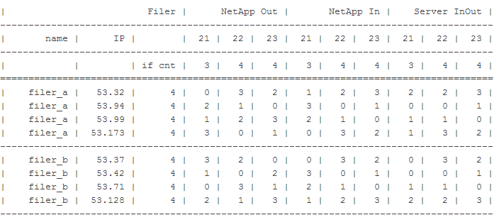
Below are the options for choosing the IP addresses of the storage , provided that there are 3 servers (with IP addresses ending in 21, 22 and 23 and the number of interfaces to the storage system of 3, 4 and 4, respectively).
The calculation was made for two networks XX.YY.52.ZZ / 24 and XX.YY.53.ZZ / 24. IP addresses for storage systems that meet the above conditions were selected.
How to use the tablet
When exchanging traffic between a server with IP XX.YY.52.22 and storage alias XX.YY.52.35, traffic:
from storage to switch (column NetApp Out, 22) goes through interface number 2 by numbering the storage from switch to storage (column NetApp In, 22) goes through interface number 1 using switch numbering from switch to server and from server to switch ( Server InOut column, 22) will go on port 1 in the server numbering and switch, respectively (not the fact that they consider the same)
It can be seen that for each server traffic with different aliases on one controller will go through different interfaces. Similarly, traffic from different servers to one IP storage system will go through different interfaces.
, IP NetApp .
++ .
.
Source: https://habr.com/ru/post/215351/
All Articles