Radio-controlled switch do it yourself. Part 3 - Switch Software
In previous posts, we designed, made and comprehensively tested a two-channel radio-controlled switch unit.
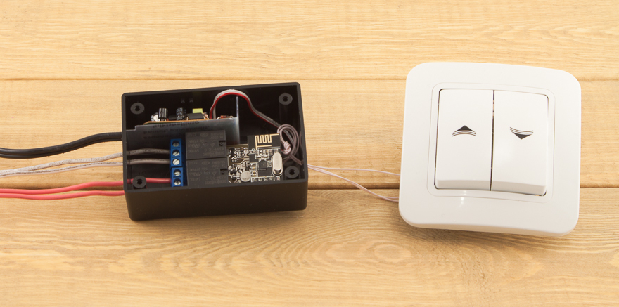
But so far it has been a “soulless piece of iron,” which, despite all its potential power embedded in the MC, does not know how.
In general, our main device (if we don’t consider connecting a radio module) is in no way more complicated than the most ordinary Arduinka, to which two buttons and a pair of LEDs are connected (in the resulting device - the LEDs are replaced with transistor switches that control the tracks, but it doesn’t change the essence ).
')
The manufactured radio switch module doesn’t have much to do development and debugging right on it:
But, as I have already noted, to “revitalize” our module, all you need is to write a sketch that would work out various presses (two buttons) and could enable / disable two loads according to our algorithm (in the layout this would be a pair of LEDs). Naturally, this is the “basic functionality”, after we deal with it - we will add “radio channel” functions.
So, in order to get a “convenient” environment for preparing our sketch, let's take a solderless breadboard, any arduino-compatible board (in my case, it is cArduino Nano), two clock buttons, two LEDs (with current limiting resistors) and several jumpers:

We collect the model, according to the concept from the first post .
I recall:
Actually, this layout will allow us to write and debug the basic functionality.
In the future, you will need to download this sketch using the programmer to the final device without alterations.
Before starting development, you should fix the basic functions that you would like to implement.
Naturally, this list of "hotelok" is in the head even before the start of work on the project, now I will just formulate
The two-channel switch will be used to control the light and ventilation in the bathroom, so the list of features turned out to be this:
These functions will be implemented a little later, but they should immediately be remembered (less will have to be rewritten):
In the course of creating software for the implementation of basic functions, we will consider the following:
The first requirement leads to the use of an array of structures for storing the module operation parameters, and the second dictates the use of a watchdog timer .
To store the channel parameters, I created the following structure:
Now you can write a simple sketch.
In the setup () function, we perform all the necessary initialization and weighed the "guard dog".
Then everything is simple: in the main program loop (loop ()) we will consistently take the following steps:
If the additional logic of the work is not needed (in my case it is automatic switching on and off of ventilation depending on the state of the light) - the chkLogic () function can be simply deleted.
Basic functions work exactly as desired.
Short button presses include the corresponding LEDs, additional logic works. By long pressing any button - the built-in LED (D13) on the Arduino is lit for one second.
Now you can implement and wireless functions.
To do this, we turn to one of my earlier posts: Wireless communications of the “smart home” .
The basic principles that I described there have withstood the test of time and have undergone very minor changes.
The following structure is suitable for working with parameters:
For the transmitted data I will use the following structure:
According to the above, my module will be described as follows:
It is seen that all the key parameters that describe the current state and time parameters are present.
Actually, it now remains to flash our module.
For firmware, I use the USBtinyISP programmer .
I stitched, checked the work - everything is OK, but it turned out that in the "pure" MK all the EEPROM bytes are set to 255, which gives the corresponding delays.
By the code above, it is clear that the installation of all time parameters is performed only through a radio channel. But I haven’t written anything about the “control module” yet, so we need to somehow solve this problem “in isolation”.
To do this, you can use examples from the EEPROM library and directly write primary (more current) values directly into the corresponding cells of non-volatile memory.
A follow-up check showed that everything now works exactly as desired.
Now the device is self-sufficient and ready to perform its main function (even without a radio channel). You can mount.
— ( ).
, — iPhone. , (, ).
- ( — ):
, — .
, , , , « ».
«» ( , , ):
, . , , .
«» , «» ( «» , / ..).
...
PS , .
, ( « ») — , ( ) , !
:
Thank you Nikita_Rogatnev for help in preparing the material for publication.
But so far it has been a “soulless piece of iron,” which, despite all its potential power embedded in the MC, does not know how.
In general, our main device (if we don’t consider connecting a radio module) is in no way more complicated than the most ordinary Arduinka, to which two buttons and a pair of LEDs are connected (in the resulting device - the LEDs are replaced with transistor switches that control the tracks, but it doesn’t change the essence ).
')
The manufactured radio switch module doesn’t have much to do development and debugging right on it:
- there is no possibility to receive diagnostic messages in the “port monitor”,
- There is no visual confirmation of which of the relays and in what condition it is, etc.
But, as I have already noted, to “revitalize” our module, all you need is to write a sketch that would work out various presses (two buttons) and could enable / disable two loads according to our algorithm (in the layout this would be a pair of LEDs). Naturally, this is the “basic functionality”, after we deal with it - we will add “radio channel” functions.
In general, of course, it would be better to start with a “mockup”, but in this case it turned out that the prototype was made later than the resulting device.
Layout
So, in order to get a “convenient” environment for preparing our sketch, let's take a solderless breadboard, any arduino-compatible board (in my case, it is cArduino Nano), two clock buttons, two LEDs (with current limiting resistors) and several jumpers:
We collect the model, according to the concept from the first post .
I recall:
- The button for the first channel is connected between pin A1 and ground (GND),
- The second channel button is A0 and GND.
- The LEDs (indicators of the operation of the corresponding transistor switches and relays in the radio switch) are connected to D3 and D4, respectively.
Actually, this layout will allow us to write and debug the basic functionality.
In the future, you will need to download this sketch using the programmer to the final device without alterations.
Before starting development, you should fix the basic functions that you would like to implement.
Desired functionality
Naturally, this list of "hotelok" is in the head even before the start of work on the project, now I will just formulate
Basic functions
The two-channel switch will be used to control the light and ventilation in the bathroom, so the list of features turned out to be this:
- By brief pressing, turn on / off the corresponding load channel (channel 1 - light, channel 2 - ventilation).
- For a long press (more than 2 seconds) - to record the fact of such pressing (“cocking the flag”), but for now do nothing extra.
- If the light is on for more than 1.5 minutes - automatically turn on the hood (for example, someone went to the shower and forgot to turn on the ventilation).
- If both channels were turned on and the first channel is turned off, automatically turn off the second channel after 10 minutes.
- In case if any load was turned on, but forgot to turn it off, turn it off automatically (each channel has its own auto-off time: 60 and 10 minutes, respectively).
When forming the list of functions - actively communicate with the home. For example, it was reasonable for me to suggest that the time after which the automatic activation of ventilation should take place is too short and there will be unnecessary alarms and, in general, all the time parameters should be able to be adjusted during operation.
Radio control
These functions will be implemented a little later, but they should immediately be remembered (less will have to be rewritten):
- The on / off commands received over the radio channel must be processed as if the switch buttons were physically pressed (i.e., full preservation of the basic logic).
- Through the radio channel you need to be able to change all the time parameters of the switch operation.
- The time parameters of the switch should be stored in non-volatile memory (so that after each shutdown of electricity there is no need to “retrain” the module).
- All parameters (current state, “long press” flags, temporary) should be available over the air both on request (response to a request) and on a regular basis (every 15 seconds - “flood” on the air with the current values of parameters).
Programming
In the course of creating software for the implementation of basic functions, we will consider the following:
- Now there are two channels, but in the future they can be more / less and the code should be such that it can be easily corrected (without significant rewriting).
- The device is built in and in case of any failure to get it out of the wall is extremely problematic.
The first requirement leads to the use of an array of structures for storing the module operation parameters, and the second dictates the use of a watchdog timer .
To store the channel parameters, I created the following structure:
typedef struct { int button; // int relay; // boolean state; // (/) unsigned long power_on; // , unsigned long auto_off; // , unsigned long time_off; // , boolean autostate; // , , unsigned long press_start; // , unsigned long press_stop; // , } Channel; Now you can write a simple sketch.
In the setup () function, we perform all the necessary initialization and weighed the "guard dog".
Then everything is simple: in the main program loop (loop ()) we will consistently take the following steps:
- We work with buttons (function button_read ()).
- We work out auto power off (autoOff ()).
- Implement additional work logic (chkLogic ()).
- Reset the watchdog timer (wdt_reset ()).
If the additional logic of the work is not needed (in my case it is automatic switching on and off of ventilation depending on the state of the light) - the chkLogic () function can be simply deleted.
I got this sketch
// #include <avr/wdt.h> #include <Bounce.h> //#define DEBUG // - // #define CH 2 // #define LONGPRESS 2000 // 2 // "" typedef struct { int button; // int relay; // boolean state; // (/) unsigned long power_on; // , unsigned long auto_off; // , unsigned long time_off; // , boolean autostate; // , , unsigned long press_start; // , unsigned long press_stop; // , } Channel; // Channel MySwitch[CH] = { 15, 3, LOW, 0, 3600000, 0, false, 0, 0, 14, 4, LOW, 0, 600000, 0, false, 0, 0 }; // Bounce. , . Bounce bouncer0 = Bounce(MySwitch[0].button,5); Bounce bouncer1 = Bounce(MySwitch[1].button,5); // boolean logicFlag = false; boolean onFlag = false; boolean offFlag = false; void setup() { wdt_disable(); // bootloop #ifndef DEBUG Serial.begin(9600); Serial.println("Start!"); pinMode(13, OUTPUT); #endif // pinMode(MySwitch[0].relay, OUTPUT); pinMode(MySwitch[1].relay, OUTPUT); // pinMode(MySwitch[0].button, INPUT); pinMode(MySwitch[1].button, INPUT); // digitalWrite(MySwitch[0].button, HIGH); digitalWrite(MySwitch[1].button, HIGH); //delay(5000); // , bootloop #ifndef DEBUG Serial.println("Ready!"); #endif wdt_enable (WDTO_8S); // 8 . } void loop() { // button_read(); // autoOff(); // chkLogic(); // wdt_reset(); } void button_read(){ // 1 if ( bouncer0.update() ) { if ( bouncer0.read() == LOW) { // MySwitch[0].press_start = millis(); } else { // , ( ) , . pressDetect(0, millis()); } } // 2 if ( bouncer1.update() ) { if ( bouncer1.read() == LOW) { MySwitch[1].press_start = millis(); } else { pressDetect(1, millis()); } } } // void doSwitch(int ch, boolean state){ // MySwitch[ch].state = state; // "" if (MySwitch[ch].state == HIGH) { // MySwitch[ch].power_on = millis(); if(MySwitch[ch].auto_off > 0) { // , MySwitch[ch].time_off = MySwitch[ch].power_on + MySwitch[ch].auto_off; MySwitch[ch].autostate = true; } #ifndef DEBUG Serial.print("ON "); Serial.println(ch); #endif } else { // MySwitch[ch].autostate = false; // MySwitch[ch].time_off = 0; #ifndef DEBUG Serial.print("OFF "); Serial.println(ch); #endif } digitalWrite(MySwitch[ch].relay,MySwitch[ch].state); } // void autoOff(){ // for (int i=0; i < CH; i++) { // - if ((millis() >= MySwitch[i].time_off) && MySwitch[i].autostate) { MySwitch[i].autostate = false; doSwitch(i, LOW); #ifndef DEBUG Serial.print("Auto OFF "); Serial.println(i); #endif } } } // void pressDetect(int ch, unsigned long p_stop) { if (MySwitch[ch].press_start != 0) { if ((p_stop-MySwitch[ch].press_start) < LONGPRESS) { // MySwitch[ch].press_stop = p_stop; #ifndef DEBUG Serial.print("Short press "); Serial.println(ch); #endif doSwitch(ch, MySwitch[ch].state ? LOW : HIGH); } else { // #ifndef DEBUG Serial.print("Long press "); Serial.println(ch); digitalWrite(13, HIGH); delay(1000); digitalWrite(13, LOW); #endif } } } // void chkLogic(){ /* ( /) 0- - / 1- - / 0 , 1.5 , 1 . 0 - 1 10 */ // 1,5 , - if ((onFlag == false) && (millis() > (MySwitch[0].power_on + 90000)) && (MySwitch[0].state == HIGH) && (MySwitch[1].state == LOW) && (MySwitch[1].press_stop < MySwitch[0].power_on)) { // doSwitch(1, HIGH); // onFlag = true; logicFlag = true; // MySwitch[1].autostate = false; #ifndef DEBUG Serial.println("Auto Logic ON"); #endif } // - - 10 if ((logicFlag == true) && (offFlag == false) && (MySwitch[1].state == HIGH) && (MySwitch[0].state == LOW)) { MySwitch[1].time_off = millis() + 600000; MySwitch[1].autostate = true; offFlag = true; #ifndef DEBUG Serial.println("Auto Logic OFF started"); #endif } // , if ((logicFlag == true) && (MySwitch[0].state == LOW) && (MySwitch[1].state == LOW)) { offFlag = false; onFlag = false; logicFlag = false; #ifndef DEBUG Serial.println("Logic reset"); #endif } // - if ((logicFlag == false) && (offFlag == false) && (MySwitch[0].press_stop > MySwitch[1].power_on) && (MySwitch[1].state == HIGH) && (MySwitch[0].state == LOW)) { logicFlag = true; #ifndef DEBUG Serial.println("Auto OFF 1 after manual OFF 0"); #endif } } Basic functions work exactly as desired.
Short button presses include the corresponding LEDs, additional logic works. By long pressing any button - the built-in LED (D13) on the Arduino is lit for one second.
Now you can implement and wireless functions.
To do this, we turn to one of my earlier posts: Wireless communications of the “smart home” .
The basic principles that I described there have withstood the test of time and have undergone very minor changes.
The following structure is suitable for working with parameters:
typedef struct{ float Value; // boolean Status; // // 0 - RO // 1 - RW char Note[16]; // } Parameter; For the transmitted data I will use the following structure:
typedef struct{ int SensorID; // int CommandTo; // ... int Command; // // 0 - // 1 - // 2 - int ParamID; // float ParamValue; // boolean Status; // // 0 - (RO) // 1 - (RW) char Comment[16]; // } Message; According to the above, my module will be described as follows:
#define SID 701 // #define NumSensors 8 // Parameter MySensors[NumSensors+1] = { // ( ) NumSensors,0,"BR 2Floor", // 0,1,"Ch.1 (Light)", // 1 () 0,1,"Ch.2 (Vent)", // 2 () 0,1,"Ch.1 (LP)", // 1 0,1,"Ch.2 (LP)", // 2 0,1,"Auto-delayON", // ( ), 0,1,"Auto-delayOFF", // ( ), 0,1,"Ch.1 AutoOFF", // 1 , 0,1,"Ch.2 AutoOFF" // 2 , }; Message sensor; It is seen that all the key parameters that describe the current state and time parameters are present.
A little more programming and the code is ready.
// #include <avr/wdt.h> #include <Bounce.h> #include <SPI.h> #include "RF24.h" #include <EEPROM.h> #define DEBUG // - // #define CH 2 // #define LONGPRESS 2000 // 2 // #define SID 701 // #define NumSensors 8 // // "" typedef struct { int button; // int relay; // boolean state; // (/) unsigned long power_on; // , unsigned long auto_off; // , unsigned long time_off; // , boolean autostate; // , , unsigned long press_start; // , unsigned long press_stop; // , } Channel; // Channel MySwitch[CH] = { 15, 3, LOW, 0, 0, 0, false, 0, 0, 14, 4, LOW, 0, 0, 0, false, 0, 0 }; // typedef struct{ float Value; // boolean Status; // // 0 - RO // 1 - RW char Note[16]; // } Parameter; // typedef struct{ int SensorID; // int CommandTo; // ... int Command; // // 0 - // 1 - // 2 - int ParamID; // float ParamValue; // boolean Status; // // 0 - (RO) // 1 - (RW) char Comment[16]; // } Message; ///////////////////////////////////////////////////////////////////////////// Parameter MySensors[NumSensors+1] = { // ( ) NumSensors,0,"701 (2F, bath)", // "" 0,1,"Ch.1 (Light)", // 1 () 0,1,"Ch.2 (Vent)", // 2 () 0,1,"Ch.1 (LP)", // 1 0,1,"Ch.2 (LP)", // 2 0,1,"Auto-delayON", // ( ), 0,1,"Auto-delayOFF", // ( ), 0,1,"Ch.1 AutoOFF", // 1 , 0,1,"Ch.2 AutoOFF" // 2 , }; Message sensor; ///////////////////////////////////////////////////////////////////////////// // Bounce. , . Bounce bouncer0 = Bounce(MySwitch[0].button,5); Bounce bouncer1 = Bounce(MySwitch[1].button,5); // boolean logicFlag = false; boolean onFlag = false; boolean offFlag = false; //RF24 radio(CE,CSN); RF24 radio(10,9); unsigned long measureTime; #define DELTAMEASURE 15000 // 15 const uint64_t pipes[2] = { 0xF0F0F0F0A1LL, 0xF0F0F0F0A2LL }; volatile boolean waitRF24 = false; void setup() { wdt_disable(); // bootloop // EEPROM prepareFromEEPROM(); #ifndef DEBUG Serial.begin(9600); Serial.println("Start!"); pinMode(13, OUTPUT); #endif for(int i=0; i<CH; i++) { // pinMode(MySwitch[i].relay, OUTPUT); // pinMode(MySwitch[i].button, INPUT); // digitalWrite(MySwitch[i].button, HIGH); } // initRF24(); // ( - ) attachInterrupt(0, isr_RF24, FALLING); measureTime = millis()+DELTAMEASURE; //delay(5000); // , bootloop #ifndef DEBUG Serial.println("Ready!"); #endif wdt_enable (WDTO_8S); // 8 . } void loop() { // button_read(); // autoOff(); // chkLogic(); // listenRF24(); // - floodRF24(); // wdt_reset(); } void button_read(){ // 1 if ( bouncer0.update() ) { if ( bouncer0.read() == LOW) { // MySwitch[0].press_start = millis(); } else { // , ( ) , . pressDetect(0, millis()); } } // 2 if ( bouncer1.update() ) { if ( bouncer1.read() == LOW) { MySwitch[1].press_start = millis(); } else { //MySwitch[1].press_stop = millis(); pressDetect(1, millis()); } } } // void doSwitch(int ch, boolean state){ // MySwitch[ch].state = state; // "" if (MySwitch[ch].state == HIGH) { // MySwitch[ch].power_on = millis(); if((MySwitch[ch].auto_off > 0) && (MySwitch[ch].auto_off != 0)) { // , MySwitch[ch].time_off = MySwitch[ch].power_on + MySwitch[ch].auto_off; MySwitch[ch].autostate = true; } #ifndef DEBUG Serial.print("ON "); Serial.println(ch); #endif } else { // MySwitch[ch].autostate = false; // MySwitch[ch].time_off = 0; #ifndef DEBUG Serial.print("OFF "); Serial.println(ch); #endif } digitalWrite(MySwitch[ch].relay,MySwitch[ch].state); } // void autoOff(){ // for (int i=0; i < CH; i++) { // - if ((millis() >= MySwitch[i].time_off) && MySwitch[i].autostate) { MySwitch[i].autostate = false; doSwitch(i, LOW); #ifndef DEBUG Serial.print("Auto OFF "); Serial.println(i); #endif } } } // void pressDetect(int ch, unsigned long p_stop) { if (MySwitch[ch].press_start != 0) { if (((p_stop-MySwitch[ch].press_start) < LONGPRESS) && (p_stop-MySwitch[ch].press_start) > 0) { // MySwitch[ch].press_stop = p_stop; #ifndef DEBUG Serial.print("Short press "); Serial.println(ch); #endif doSwitch(ch, MySwitch[ch].state ? LOW : HIGH); } else { // #ifndef DEBUG Serial.print("Long press "); Serial.println(ch); digitalWrite(13, !digitalRead(13)); #endif // MySensors[ch+3].Value = 1; // "" // "" , - ( ) // "" } } } // void chkLogic(){ /* ( /) 0- - / 1- - / 0 , 1.5 , 1 . 0 - 1 10 */ // ( MySensors[5].Value - ), - if ((onFlag == false) && (millis() > (MySwitch[0].power_on + MySensors[5].Value*60000)) && (MySensors[5].Value != 0) && (MySwitch[0].state == HIGH) && (MySwitch[1].state == LOW) && (MySwitch[1].press_stop < MySwitch[0].power_on)) { // doSwitch(1, HIGH); // onFlag = true; logicFlag = true; // MySwitch[1].autostate = false; #ifndef DEBUG Serial.println("Auto Logic ON"); #endif } // - - (( MySensors[6].Value - ) if ((logicFlag == true) && (offFlag == false) && (MySensors[6].Value != 0) && (MySwitch[1].state == HIGH) && (MySwitch[0].state == LOW)) { MySwitch[1].time_off = millis() + MySensors[6].Value*60000; MySwitch[1].autostate = true; offFlag = true; #ifndef DEBUG Serial.println("Auto Logic OFF started"); #endif } // , if ((logicFlag == true) && (MySwitch[0].state == LOW) && (MySwitch[1].state == LOW)) { offFlag = false; onFlag = false; logicFlag = false; #ifndef DEBUG Serial.println("Logic reset"); #endif } // - if ((logicFlag == false) && (offFlag == false) && (MySwitch[0].press_stop > MySwitch[1].power_on) && (MySwitch[1].state == HIGH) && (MySwitch[0].state == LOW)) { logicFlag = true; #ifndef DEBUG Serial.println("Auto OFF 1 after manual OFF 0"); #endif } } void floodRF24(){ // (1 DELTAMEASURE ) // ! - ! if (millis() > measureTime){ getValue(); // //for (int i=1; i<=NumSensors; i++) { // (, - ) for (int i=1; i<=4; i++) { sendSlaveMessage(0, i); delay(20); } measureTime = millis()+DELTAMEASURE; } } void getValue(){ MySensors[1].Value = MySwitch[0].state; MySensors[2].Value = MySwitch[1].state; return; } // void isr_RF24(){ waitRF24 = true; } // (, , ) - (slave) // ! ParamID void sendSlaveMessage(int To, int ParamID) { // radio.stopListening(); radio.openWritingPipe(pipes[0]); radio.openReadingPipe(1,pipes[1]); delay(20); // sensor.SensorID = SID; sensor.CommandTo = To; sensor.Command = 0; sensor.ParamID = ParamID; sensor.ParamValue = MySensors[ParamID].Value; sensor.Status = MySensors[ParamID].Status; memcpy(&sensor.Comment,(char*)MySensors[ParamID].Note, 16); // RF24 bool ok = radio.write( &sensor, sizeof(sensor) ); delay (20); // radio.openWritingPipe(pipes[1]); radio.openReadingPipe(1,pipes[0]); radio.startListening(); } // void listenRF24(){ // , if (waitRF24) { waitRF24 = false; // , // if (radio.available()) { bool done = false; while (!done) { done = radio.read( &sensor, sizeof(sensor) ); // - if (sensor.CommandTo == SID) { // ( , , , ) doCommand(sensor.SensorID, sensor.Command, sensor.ParamID, sensor.ParamValue, sensor.Status, sensor.Comment); } } } } } // ( , , ID, , , ) - void doCommand(int From, int Command, int ParamID, float ParamValue, boolean Status, char* Comment) { // - , - switch (Command) { case 0: // break; case 1: getValue(); // sendSlaveMessage(From, ParamID); break; case 2: // setValue(From, ParamID, ParamValue, Comment); // sendSlaveMessage(From, ParamID); break; default: break; } } // (, , , ) void setValue(int From, int ParamID, float ParamValue, char* Comment) { // - if(MySensors[ParamID].Value != ParamValue){ // / - ( ) "" // "" ( ) if((ParamID<3) && (MySwitch[ParamID-1].state != (boolean)ParamValue)) { // " " MySwitch[ParamID-1].press_start = millis()-50; // " " ( "" ) pressDetect(ParamID-1, millis()); } else { // MySensors[ParamID].Value = ParamValue; // , - EEPROM if (ParamID > 4){ EEPROM.write(ParamID-5, MySensors[ParamID].Value); // if(ParamID > 6) { MySwitch[ParamID-7].auto_off = ((unsigned long)MySensors[ParamID].Value)*60000; } } } } } void initRF24(){ radio.begin(); radio.setRetries(15,15); // ( ) radio.setChannel(100); radio.openWritingPipe(pipes[0]); radio.openReadingPipe(1,pipes[1]); radio.startListening(); // } void prepareFromEEPROM() { // 4 = 4 1 : // 0 - ( ), // 1 - ( ), // 2 - 1 , // 3 - 2 , for(int i=0; i<4; i++) { MySensors[i+5].Value = EEPROM.read(i); } // for(int i=0; i<CH; i++) { MySwitch[i].auto_off = ((unsigned long)MySensors[i+7].Value)*60000; } } Actually, it now remains to flash our module.
For firmware, I use the USBtinyISP programmer .
I stitched, checked the work - everything is OK, but it turned out that in the "pure" MK all the EEPROM bytes are set to 255, which gives the corresponding delays.
By the code above, it is clear that the installation of all time parameters is performed only through a radio channel. But I haven’t written anything about the “control module” yet, so we need to somehow solve this problem “in isolation”.
To do this, you can use examples from the EEPROM library and directly write primary (more current) values directly into the corresponding cells of non-volatile memory.
A follow-up check showed that everything now works exactly as desired.
Once again I will repeat my basic principle of the devices of my “smart home”: each created device is made to achieve a specific goal and it should work independently .
Now the device is self-sufficient and ready to perform its main function (even without a radio channel). You can mount.
Module installation
— ( ).
, — iPhone. , (, ).
- ( — ):
, — .
, , , , « ».
«» ( , , ):
- .
- ( , , — ).
- ( «», « »).
- ( , ).
- , ( — , , «- » ).
- .
, . , , .
Result
«» , «» ( «» , / ..).
...
PS , .
:
( ) . / 220 ( , — ). 5, ( ).
( ) . / 220 ( , — ). 5, ( ).
, ( « ») — , ( ) , !
:
Thank you Nikita_Rogatnev for help in preparing the material for publication.
Source: https://habr.com/ru/post/215177/
All Articles