Using DSP SB Live! for the benefit of radio amateurs (KX Driver's) - Part [2/2]

First part: Using the DSP SB Live! for the benefit of radio amateurs (KX Driver's) - Part [1/2]
The practical part, problems, conclusions.
')
Under the cat a lot of video.
Content
9. Practical research.
9.1. Experience 1
9.2.Experience 2
9.3.Experience 3
9.4. Experience 4
10. Problems
10.1.Problema limited sound DSP resources
10.2. Problem of one physical input
10.3. The problem of slow reconfiguration of a large number of identical filters
10.4. The problem of the lack of a creative sound card
findings
List of sources used
9. Practical research.
It is time to find out how good the theory is in practice. Performance testing, convenience and subjective assessment of the result will be carried out.
9.1. Experience 1
Parameters and equipment:
- Computer
- Receiver P-309 ( picture )
- Antenna Inv-V 80M
- Time 9-10 hours in Moscow
SSB filter check
Receiver P-309 has a very wide band and receives both side bands at once. It is assumed that the use of SSB filter will give a good result. Sound processing was carried out on a computer only to increase the signal level. Also, due to the low sampling rate (8 KHz), no filter can be heard without interference, which have frequencies above 4 KHz.
Weakly received station. Range 80 m.
Without a filter:
With filter:
Very poorly received station. Range 80 m.
Without a filter:
With filter:
Another station range of 80 meters.
Conclusions: the use of the filter allows to slightly improve the reception of the signal, but, unfortunately, no significant changes were noticed. It is almost very long to change the parameters of the filter chain in order to change the total bandwidth.
CW filter check
It is assumed that using the CW filter will give a good result. In addition, in the CW filter there is no need to change the parameters, which should affect the efficiency of working with it.
In the example, the state of the ether without processing, then smoothly turning on the filter, and then turning off.
Conclusions: the use of the CW filter gave a definitely positive result, but on the basis of one experience it is impossible to say. It is also necessary to check how the filter will work if there are several more stations nearby.
9.2.Experience 2
Parameters and equipment:
- Computer
- FT-850 transceiver ( picture )
- Antenna 2 meters of wire in the room
- Time 15-16 hours in Moscow
CW filter check
It is assumed that using the CW filter will give a good result. In addition, it turned out that in the previous experiment, the filters were not selected the correct parameters (Q = 1 instead of 20), which did not allow to fully check the quality of work.
In the examples, the state of the ether without processing, turning on and off the filter.
When used, it was noticed that after passing the filter at the telegraph parcels, the fronts are noticeably smoothed ( here we have to understand the basics of filtering signals: the narrower the band, the lower the speed of manipulation ). Also due to the fact that the filter is very narrow, you need fine tuning. When using the crossfader, the ratio of raw to processed signal was set to 75% / 25%. When tuned exactly to the station, the signal began to pass through both filters, it was folded with a crossfader and the signal level increased markedly. This made it clear that the adjustment was made precisely and you can switch completely to a narrow-band filter.
Conclusions: the use of the CW filter gave a positive result, but it is necessary to check how the filter will work if there are several stations nearby.
9.3.Experience 3
Parameters and equipment:
Parameters and equipment:
- Computer
- FT-850 transceiver ( picture )
- Antenna Inv-V 80M
- Time 1:00 am Moscow time
It is planned to test the filter in difficult conditions with a large number of nearby stations.
SSB contest (competition)
In the example at the beginning, no filter is used. Then 3 filters of 300 Hz are switched on in series. Then Includes 3 filters of 2700 Hz and below. Then the frequency is released to 1800 Hz. Quickly change the bandwidth fails.
Conclusions: The use of filters for receiving SSB is still difficult. Strong enough signals are well perceived both with the filter, and without. Narrowing the band does not help filter out the signals of nearby stations, which manifest themselves in the form of RF interference around 3 kHz. Using the same software DSP easily and quickly fixes this problem. Software DSP filters have steeper slopes of frequency response, but the sound subjectively seems to be more dry.
CW filter check
It is planned to test the filter in difficult conditions with a large number of nearby stations.
CW contest (competition)
In the example, the filter is turned on and off several times. And just one BandPass filter is enough for normal filtering. The use of one filter also smoothes the fronts of telegraphic packages less.
Conclusions: I consider the use of a filter to receive a telegraph successful. Achieved high quality filtering. Also, due to the fact that only one filter is used, it is quite easy and fast to change its parameters. The work with the telegraph on the software DSP was also tested and also showed good results. In connection with this, it is planned to conduct another experience comparing the quality of filtering software and hardware DSP.
9.4. Experience 4
Parameters and equipment:
- Computer
- The program DSP Filter Ver1.11 JE3HHT 2000.
- FT-850 transceiver ( picture )
- Antenna Inv-V 80M
- Time 12:00 am Moscow time
Comparison of hardware and software SSB filter
It is planned to compare the operation of the software filter and the hardware filter on the DSP.
In the original example, the next station is heard (about 3 KHz). In the example with the program filter, it is audible that the filter band is changing from 2700 to 1800 Hz. Interference from a nearby station is easily suppressed, the band changes quickly and quickly with the press of a single button. In principle, the hardware DSP also copes with the task, but not so quickly: one filter is not enough, and changing the band on three filters at once is not possible quickly.
Conclusions: The use of software DSP easily and quickly suppresses interference from a nearby station. Software DSP filters have steeper slopes of frequency response, but the sound seems subjectively drier, apparently due to the lack of low frequencies. Hardware DSP allows you to smoothly change the filter band, with both the top and bottom. The disadvantage is that the parameters of the chain of the three filters are not as fast and convenient to change as in the program filter.
Comparison of hardware and software CW filter
It is planned to compare the operation of the software filter and the hardware filter on the DSP.
Conclusions: I consider the use of both filters to receive telegraph success. Achieved high quality filtering. As in the case of software DSP and hardware, when narrowing the band, the signal becomes less clear, and the fronts are smooth. The minus of the software DSP was a delay of about one second, which slightly hinders the tuning to the frequency.
In the process of experimenting with hardware DSP, to switch between wide and narrow strip it turned out to be more convenient not to use the crossfader but to change the Q parameter of the filter. After tuning exactly to the frequency (see picture), you can improve the Q-factor of the filter, but not to the maximum, but before reaching the necessary filtering, since with the improvement of the quality factor of the filter, the clarity of the telegraph packages is reduced.

10. Problems
This section will look at problems when using both the KX driver system and the hardware that is used to communicate with the transceiver. Possible ways (if any) of solving these problems will also be proposed. General recommendation: save DSP schemes to files so that you do not draw them again each time.
10.1.Problema limited sound DSP resources
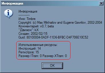
Due to the fact that the sound processing is conducted by the EMU 10k1 / k2 hardware-signal processor, that is, there are certain limitations. The signal processor runs a sound processing program in its own physical memory, using its own registers. All these resources have certain limits. Each signal processing object consumes certain signal processor resources.
When creating a scheme in the DSP, you can always see the remaining resources:

Also, each schema object in the context menu (right mouse button on the object) has the “Info ...” item.
Troubleshooting
It is known from the documentation that boards with an EMU 10k2 chip have better parameters and more resources, therefore it is better to use it. You will never be able to completely solve the resource problem, so you need to take the following steps: when creating large resource-intensive schemes, you need to monitor free resources and remove unnecessary resource-intensive elements (FXMix2, Reverb Lite, Stereo Chorus, xrouting, Surrounder from the default scheme). Since the radio signal is mainly MONO, then use mono-objects; use both channels sequentially.
| An object | Instructions | Registers | Itram | Xtram |
|---|---|---|---|---|
| FXBus | 0 | sixteen | 0 | 0 |
| prolog | 14 | 28 | 0 | 0 |
| epilog | 76 | 68 | 0 | 0 |
| xrouting | 42 | 62 | 0 | 0 |
| peak | four | 6 | 0 | 0 |
| Mono mix | 6 | 2 | 0 | 0 |
| EQ Bandpass | 18 | 20 | 0 | 0 |
| EQ Notch | 18 | 20 | 0 | 0 |
| EQ Highpass | 18 | 20 | 0 | 0 |
| EQ Lowpass | 18 | 20 | 0 | 0 |
| EQ G10 | 104 | 88 | 0 | 0 |
| Timbre | 14 | 15 | 0 | 0 |
| EQ P1 | 14 | 15 | 0 | 0 |
| EQ P1 (mono) | 7 | eleven | 0 | 0 |
| EQ P5 | 55 | 49 | 0 | 0 |
| EQ P5 (mono) | 28 | 37 | 0 | 0 |
| Reverb lite | 77 | 131 | 2943 | 62590 |
| Reverb R | 90 | 138 | 2943 | 62592 |
| Stereo chorus | 28 | 38 | 2888 | 0 |
10.2. Problem of one physical input
Despite the fact that the card has many physical inputs (linear, microphone), recording can be made only from one source (*). Therefore, if there is a desire to use the card to process sound for both reception and transmission, then difficulties may arise: for processing, you need to send a signal from the receiver and a signal from a microphone. Inside the DSP, there is no difficulty in separating the signals; to bring them separately from each other to different physical outputs, too.
Troubleshooting
- Send both signals (from microphone and receiver) to the line input, but to different channels (for example, microphone to the left, receiver to the right)
- Since only reception or transmission can be conducted at the same time, one of the signals can be sent to the line input, switching them, for example, using a relay.
- Mix both signals and feed to the line input. If the receiver is “silent” during transmission, then there should be no problems.
- Try the version with mixing, but only by means of the card itself. In the mode when monomix is selected as an input, then signals from all physical inputs will have to be recorded. Then the receiver is connected to the line input, and the microphone to the microphone. If this option works, then the issue with a microphone amplifier will also be solved, which will have to be used when connecting the microphone to the line input
10.3. The problem of slow reconfiguration of a large number of identical filters
If you create a chain of a large number of filters (an example of an SSB filter), then if you need to change the parameter of this entire filter, you will need to change the parameters in each. This is a long time, moreover, during this time, the situation on the air can change significantly. A normal solution to this problem has not yet been found.
Troubleshooting
Control filter parameters with external physical devices (MIDI).
Create multiple configurations and switch between them quickly
Create a “radio amateur” filter, but for this you need to be able to write under KX's
10.4. The problem of the lack of a creative sound card
The fact is that quite good sound cards are now built into modern motherboards. The need for a sound card, as in a separate device, has long disappeared. If anyone buys a card separately, then more often or some of the cheapest, or vice versa very serious. It is also difficult to find Creative SB Live. The price of it at one time fell even to the level of about 950r. A large number of Audigy sound cards appeared and it is not clear whether they are supported by KX drivers.
Troubleshooting
- Weigh the pros and cons, see the software DSPs, calculate the budget and decide if you need this card.
- View a list of supported hardware on the KX driver developer site.
findings
In the process of writing this article, I learned a lot about KX drivers and was able to better understand their use. Understood the use of KX-drivers in everyday work on the PC, when listening to sound, when recording. I also tried to use a sound card for signal processing when working on the air. According to certain parameters, the KX-driver system loses to the program DSP filters: by its convenience and ease of control; according to other parameters, it shows quite good results: no delay in signal processing, no processor load, greater flexibility in creating processing schemes, the signal after processing is more natural. It also seduces the KX with ample possibilities for processing the signal from a microphone before broadcasting: for HiFi SSB lovers, signal processing uses special sound processing devices (equalizers, compressors, echo processors), which modern models are now almost completely implemented using DSP. Using the creative board together with the KX drivers will save a bit of budget when creating a mini HiFi SSB “studio”. And in general, it is very nice to have additional features from a seemingly ordinary card for 1000 rubles.
I think on this my experiments with KX and Live are not finished, because The possibilities of asio, self-programming dsp remained unexplored.
List of sources used
Source: https://habr.com/ru/post/215099/
All Articles