LED backlight monitor with your own hands
Time passes imperceptibly and it would seem that the newly purchased equipment is already failing. So, having worked their 10,000 hours, they ordered my monitor lamps to live for a long time (AOC 2216Sa). Initially, the backlight did not turn on the first time (after turning on the monitor, the backlight was turned off after a few seconds), which was decided by turning the monitor on / off again, over time the monitor had to be turned off / off 3 times, then 5, then 10, and at some point I could not turn on the backlight already regardless of the number of attempts to turn on. The lamps of God taken to the world turned out to be with blackened edges and legally went for scrap. An attempt to put replacement lamps (new lamps of the right size were purchased) did not succeed (several times the monitor was able to turn on the backlight, but quickly went back to on-off mode) and finding out the reasons for what could be the problem already in the monitor's electronics brought me to the idea that it would be easier to assemble your own monitor backlight on LEDs than to repair the existing inverter circuit for CCFL lamps, especially since the network already came across articles showing the fundamental possibility of such a replacement.
We disassemble the monitor
On the topic of disassembling the monitor, quite a few articles have already been written, all the monitors are very similar to each other, so in brief:
1. Turn off the monitor delivery fastener and the only bolt at the bottom that holds the back wall of the case
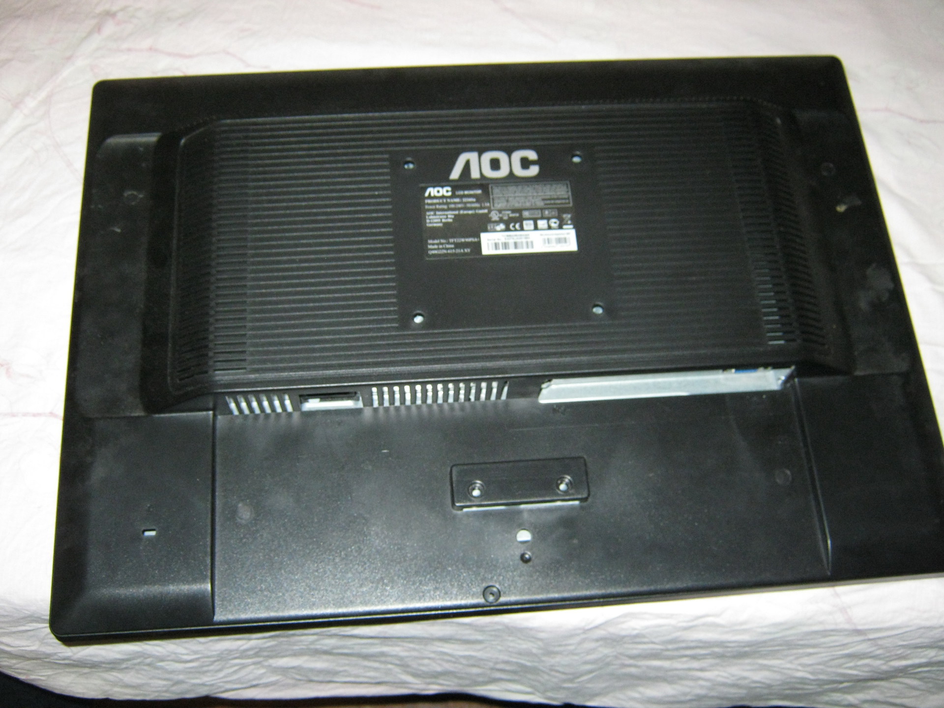
2. At the bottom of the case there are two lashes between the front and back of the case, one of which we shove a flathead screwdriver and begin to remove the cover from the latches along the entire perimeter of the monitor (simply turning the screwdriver carefully around its axis and lifting the case cover). There is no need to exert excessive efforts, but the body is only hard to be removed from the latches for the first time (I opened it many times during the repair, so the latches began to be removed with time much easier).
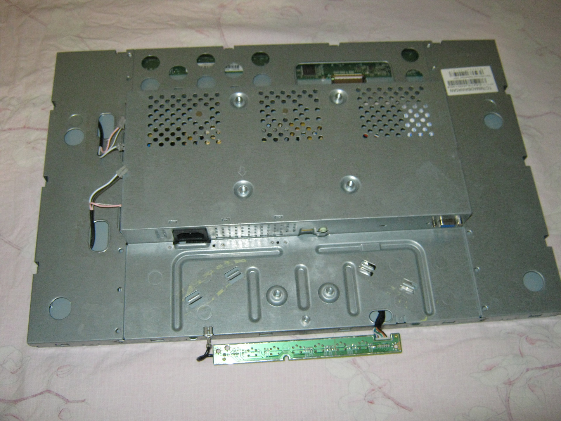
3. We have a view of the installation of the inner metal frame in front of the case:

We take out the board with the buttons from the latches, remove (in my case) the speaker connector and bend the two latches on the bottom out of the inner metal case.
4. On the left you can see 4 wires connecting the backlight. We take them out slightly squeezing, because To prevent falling out of the connector is made in the form of a small clothespins. We also take out a wide loop going to the matrix (at the top of the monitor), squeezing its connector on the sides (because there are side latches in the connector, although at first glance at the connector this is not obvious):
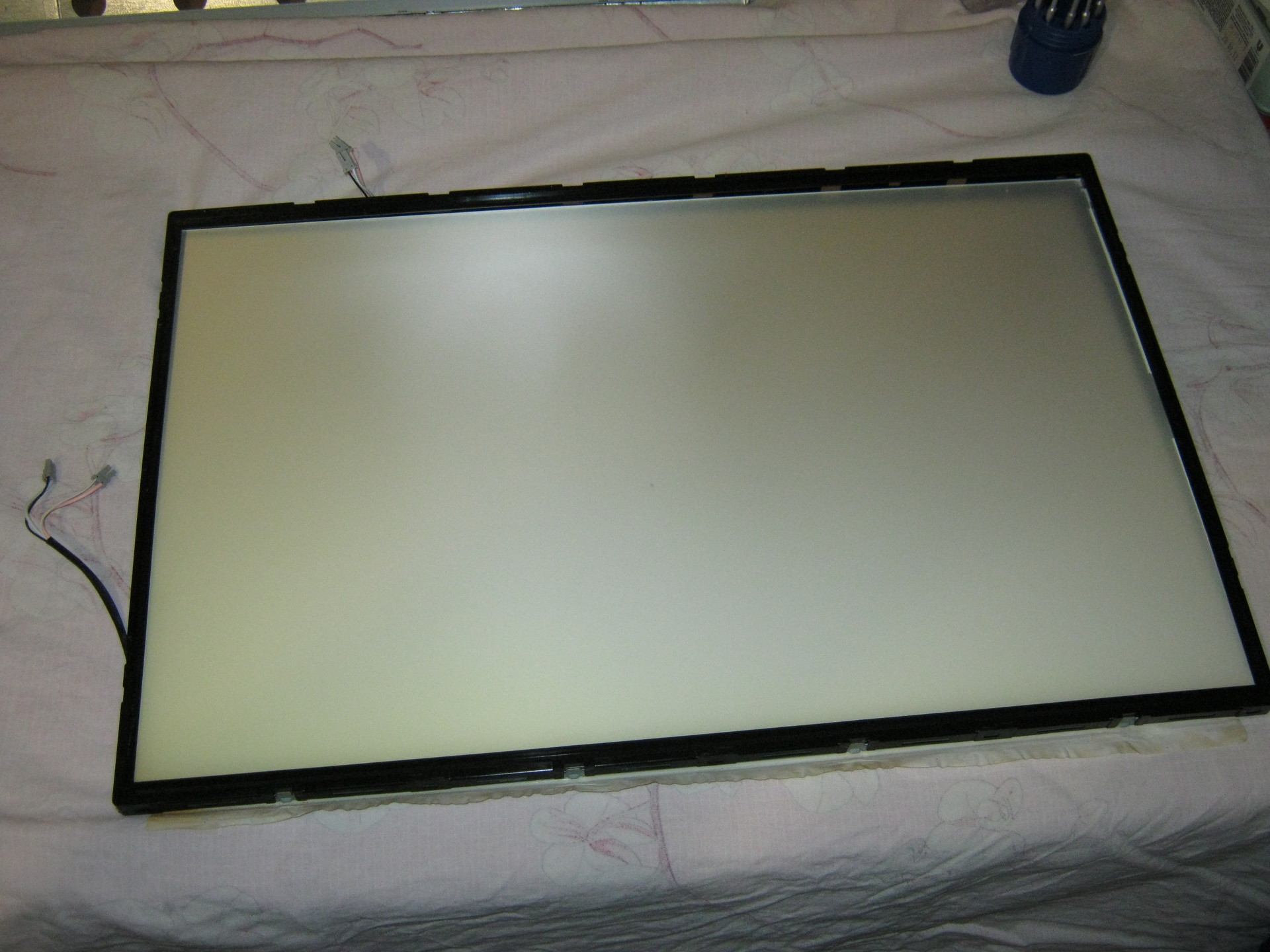
5. Now it is necessary to disassemble the “sandwich” containing the matrix itself and the backlight:

Along the perimeter are the latches, which are opened by slightly using a flat screwdriver. First, the metal frame of the supporting matrix is removed, after which you can unscrew three small bolts (a regular crosshead screwdriver will not work because of their miniature size, you will need a particularly small one) holding the control board of the matrix and the matrix can be removed (it is best to place the monitor on a hard surface, such as a table covered cloth matrix down, unscrewing the control board, put it on the table, unrolling through the end of the monitor and just open the case with the backlight, raising it vertically upwards, and the matrix will remain put on the table. It can be covered with something not to get dusty, but assembled exactly in the reverse order — that is, cover the matrix lying on the table with the assembled illuminated case, wrap the cable to the control board and screw the control board to carefully lift the unit into assembled).
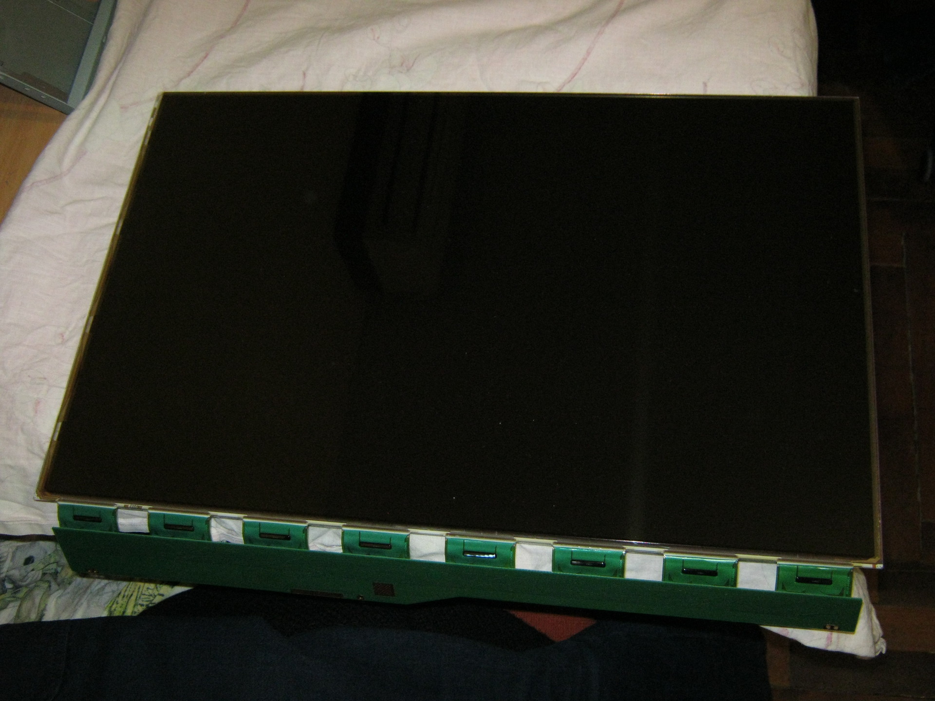
It turns out the matrix separately:
And the backlit unit separately:
The backlit unit is disassembled in the same way, only instead of the metal frame, the backlight is held by a plastic frame, which simultaneously positions the plexiglass used to scatter the light of the backlight. Most of the latches are located on the sides and similar to those that held the metal frame of the matrix (they are opened by prying with a flat screwdriver), but there are several latches on the sides opening inwards (they need to be pressed with a screwdriver so that the latches go inside the case).
At first, I memorized the position of all the parts to be removed, but then it turned out that they could not be “correctly” assembled, and even if the parts look absolutely symmetrical, the distances between the latches on different sides of the metal frame and the fixing projections on the sides of the plastic frame that hold the backlight will not allow them to be “wrong” ".
That's all - we disassembled the monitor.
LED strip light
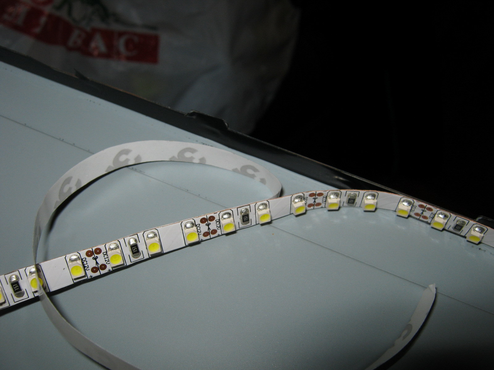
Initially, it was decided to make the backlight of the LED strip with white LEDs 3528 - 120 LEDs per meter. The first thing that turned out to be - the width of the tape is 9 mm, and the width of the backlight lamps (and the seat for the tape) is 7 mm (in fact, there are backlights of two standards - 9 mm and 7 mm, but in my case they were 7 mm). Therefore, after inspecting the tape, it was decided to cut 1 mm from each edge of the tape, since this did not affect the conductive tracks on the front of the tape (and on the back along the entire tape there are two wide supply wires, which will not lose from 1 mm of their properties on the 475 mm backlight length, since the current will be small). No sooner said than done:

Similarly, the LED strip is neatly trimmed along the entire length (in the photo an example of what happened before and what happened after trimming).
We will need two strips of tape of 475 mm (19 segments of 3 LEDs in a strip).
I wanted the monitor backlight to work the same way as the standard one (i.e., the monitor controller turned on and off), but I wanted to adjust the brightness “manually”, like on old CRT monitors, since This is a frequently used function and I’ve gotten tired of scrolling through the on-screen menus each time (in my monitor, the left and right keys do not adjust the monitor modes, but the volume of the built-in speakers, so the modes had to be changed each time through the menu). To this end, a manual on my monitor was found on the network (to whom it is useful - attached at the end of the article) and on the page with the Power Board according to the scheme found + 12V, On, Dim and GND that interest us.

On - signal from the control board to turn on the backlight (+ 5V)
Dim - PWM control backlight brightness
+ 12V turned out to be far not 12, but somewhere 16V without a load of illumination and somewhere 13.67V with under load
It was also decided to not make any PWM adjustments for the backlight brightness, but to power the backlight with direct current (at the same time, the issue is resolved that some PWM backlight monitors work at a not very high frequency and some people get a little more tired of this). In my monitor, the frequency of the “native” PWM was 240 Hz.
Further, on the board, contacts were found for which the On signal (marked red) and + 12V to the inverter unit are on (the jumper that needs to be evaporated to de-energize the inverter unit is marked green). (you can enlarge the photo to see the marks):

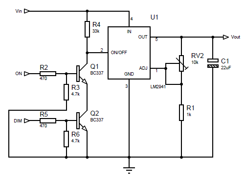
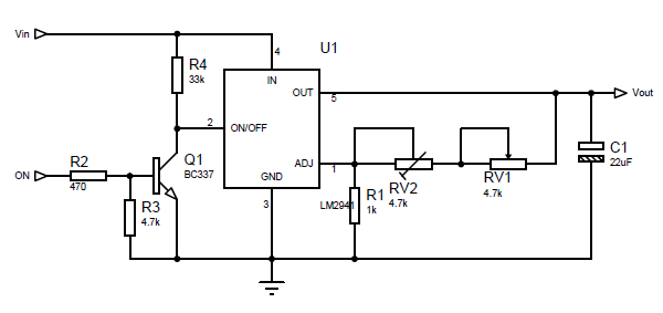
The basis of the control circuit was to take the LM2941 linear regulator mainly because at current up to 1A it had a separate On / Off control terminal, which was supposed to be used to control the on / off of the backlight with the On signal from the monitor control board. However, in LM2941 this signal is inverted (i.e. there is voltage at the output when the On / Off input is zero potential), so I had to assemble an inverter on one transistor to match the On direct signal from the control board and the inverted input LM2941. The scheme does not contain any other excesses:
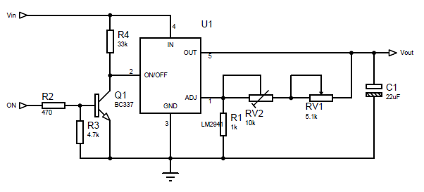
The output voltage for the LM2941 is calculated using the formula:
Vout = Vref * (R1+R2)/R1where Vref = 1.275V, R1 in the formula corresponds to R1 in the circuit, and R2 in the formula corresponds to a pair of resistors RV1 + RV2 in the circuit (two resistors are introduced for smoother brightness control and reduction of the voltage range regulated by the variable resistor RV1).
As R1, I took 1 kOhm, and R2 is selected according to the formula:
')
R2=R1*(Vout/Vref-1)The maximum voltage we need for the tape is 13V (I took more than the nominal 12V so as not to lose brightness, and the tape will survive this slight overvoltage). Those. the maximum value of R2 = 1000 * (13 / 1.275-1) = 9.91 kOhm. The minimum voltage at which the tape still somehow glows - about 7 volts, i.e. the minimum value of R2 = 1000 * (7 / 1.275-1) = 4.49kOhm. R2, we consist of a variable resistor RV1 and multi-turn trimmer RV2. Resistance RV1 we get 9.91 kOhm - 4.49 kOhm = 5.42 kOhm (we choose the nearest RV1 value - 5.1 kOhm), and RV2 is set at about 9.91-5.1 = 4.81 kOhm (actually it is best to first assemble the circuit, set the maximum resistance RV1 and measure the voltage on LM2941 output set the resistance of RV2 so that the output is the desired maximum voltage (in our case, about 13V).
LED strip mounting
Since after cutting the tape by 1 mm along the ends of the tape, the power supply wires were bare, I glued the insulating tape to the body where the tape would be glued (unfortunately not blue but black). The tape is glued on top (it is good to heat the surface with a hair dryer, because the adhesive tape is much better glued to the warm surface):
Next mounted rear film, plexiglass and filters that lay on top of plexiglass. Along the edges I propped the tape with pieces of an eraser (so that the edges on the tape did not leave):
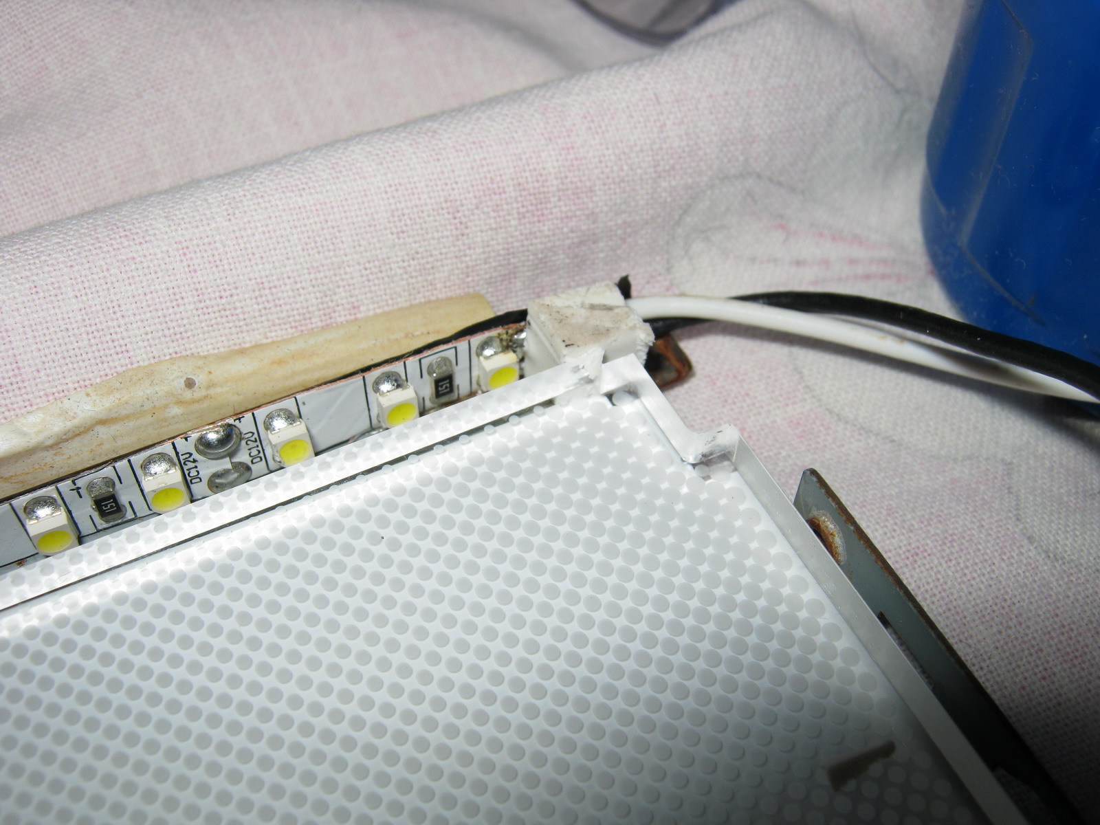
After that, the backlight unit is assembled in reverse order, the matrix is installed in its place, the backlight wires are brought out.
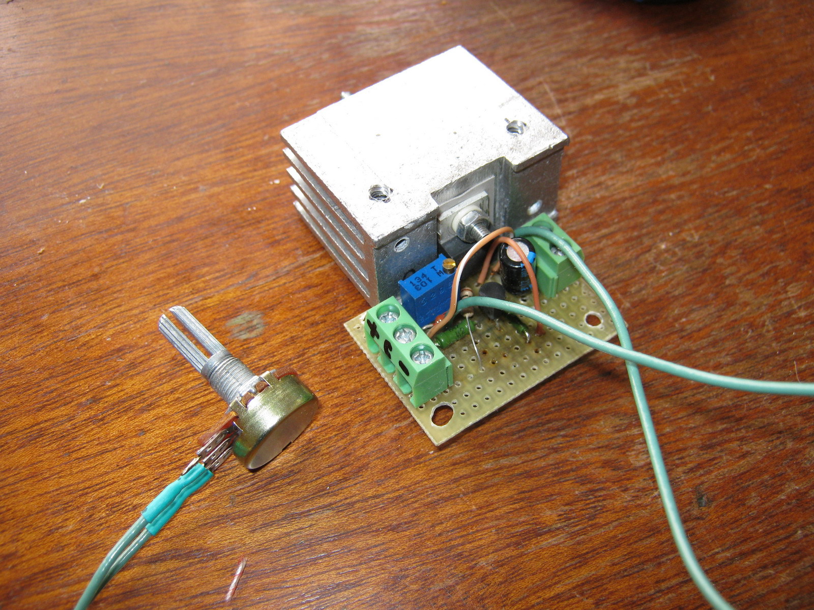
The scheme was assembled on a breadboard (due to simplicity, I decided not to part the board), mounted on bolts through the holes in the back wall of the metal monitor case:
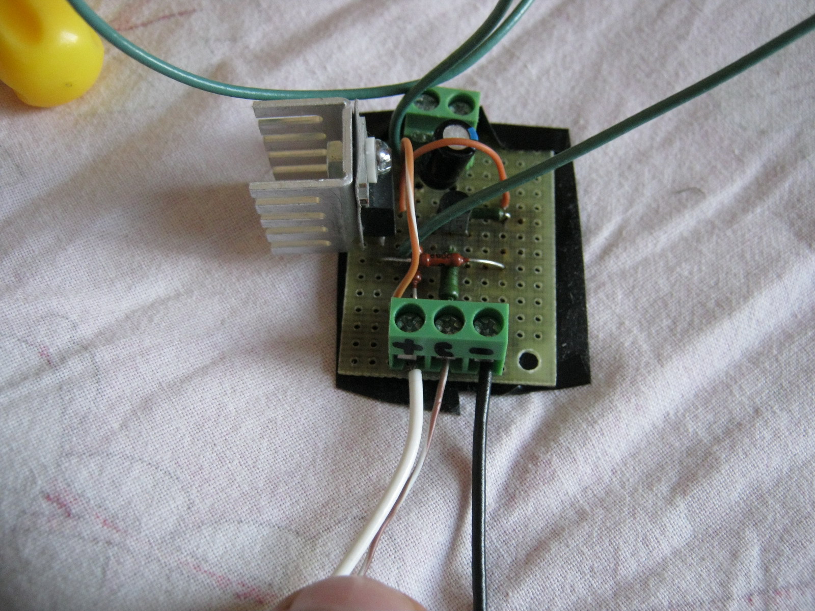
The power and control signal On were started from the power supply board:
The calculated power allocated to the LM2941 is calculated by the formula:
Pd = (Vin-Vout)*Iout +Vin*IgndFor my case it is Pd = (13.6-13) * 0.7 + 13.6 * 0.006 = 0.5 Watt, so it was decided to get by with the smallest radiator for the LM2941 (planted through a dielectric gasket since it is not isolated from the ground in the LM2941).
The final assembly showed quite well the performance of the structure:
Of the advantages:
- Uses standard LED strip
- Simple control board
Of the disadvantages:
- Insufficient backlight brightness in bright daylight (the monitor is opposite the window)
- LEDs in the tape are not often enough, so you can see small light cones from each individual LED near the top and bottom edges of the monitor
- The white balance is slightly disturbed and goes slightly to greenish shades (most likely it is decided by adjusting the white balance of either the monitor or the video card itself)
It is a good, simple and low cost repair option backlight. It is quite comfortable to watch movies or use the monitor as a kitchen TV, but probably not for everyday work.
Brightness adjustment with PWM
For those workers who, unlike me, do not recall with nostalgia the analog knobs for brightness and contrast on old CRT monitors, you can make control from the standard PWM generated by the monitor control card without removing any additional controls to the outside (without drilling the monitor case). To do this, it is enough to assemble an AND-NOT circuit on the On / Off input of the regulator on two transistors and remove the brightness control on the output (set the output voltage to 12-13 V constant). Modified scheme:
The resistance of the trimmer resistor RV2 for a voltage of 13V should be in the region of 9.9kΩ (but it is better to set exactly when the regulator is on)
More dense LED backlight
To solve the problem of insufficient brightness (and at the same time evenness) of the backlight, it was decided to install more LEDs and more often. Since it turned out that buying light-emitting diodes individually is more expensive than buying 1.5 meters of tape and dropping them out from there a more economical option was chosen (pull the LEDs out of the tape).
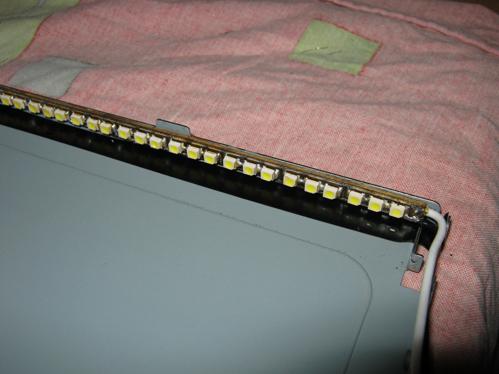
The 3528 LEDs themselves were placed on 4 strips 6 mm wide and 238 mm long with 3 LEDs in series in 15 parallel assemblies on each of the 4 strips (wiring for LED boards is attached). After soldering LEDs and wires, the following is obtained:
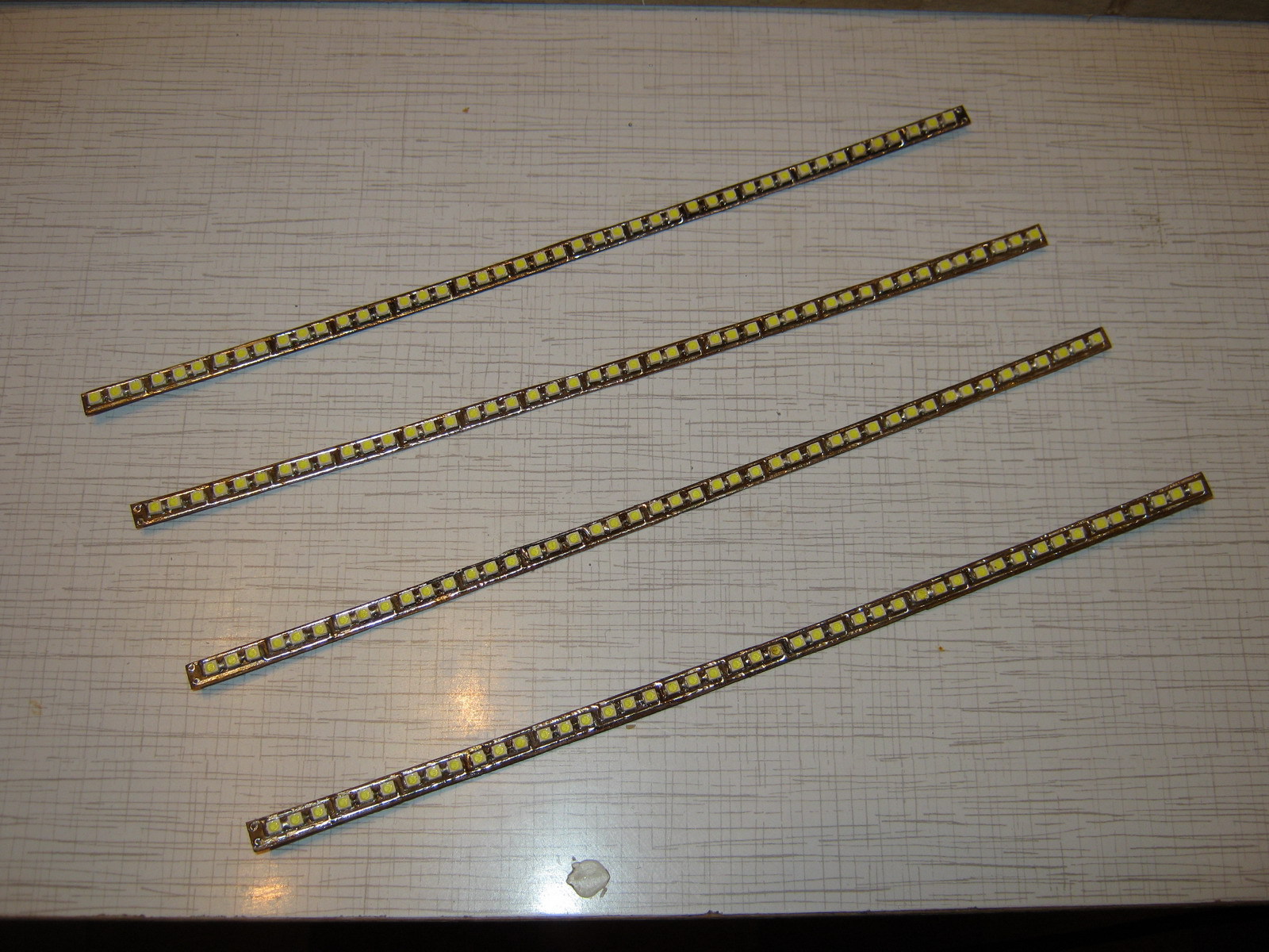
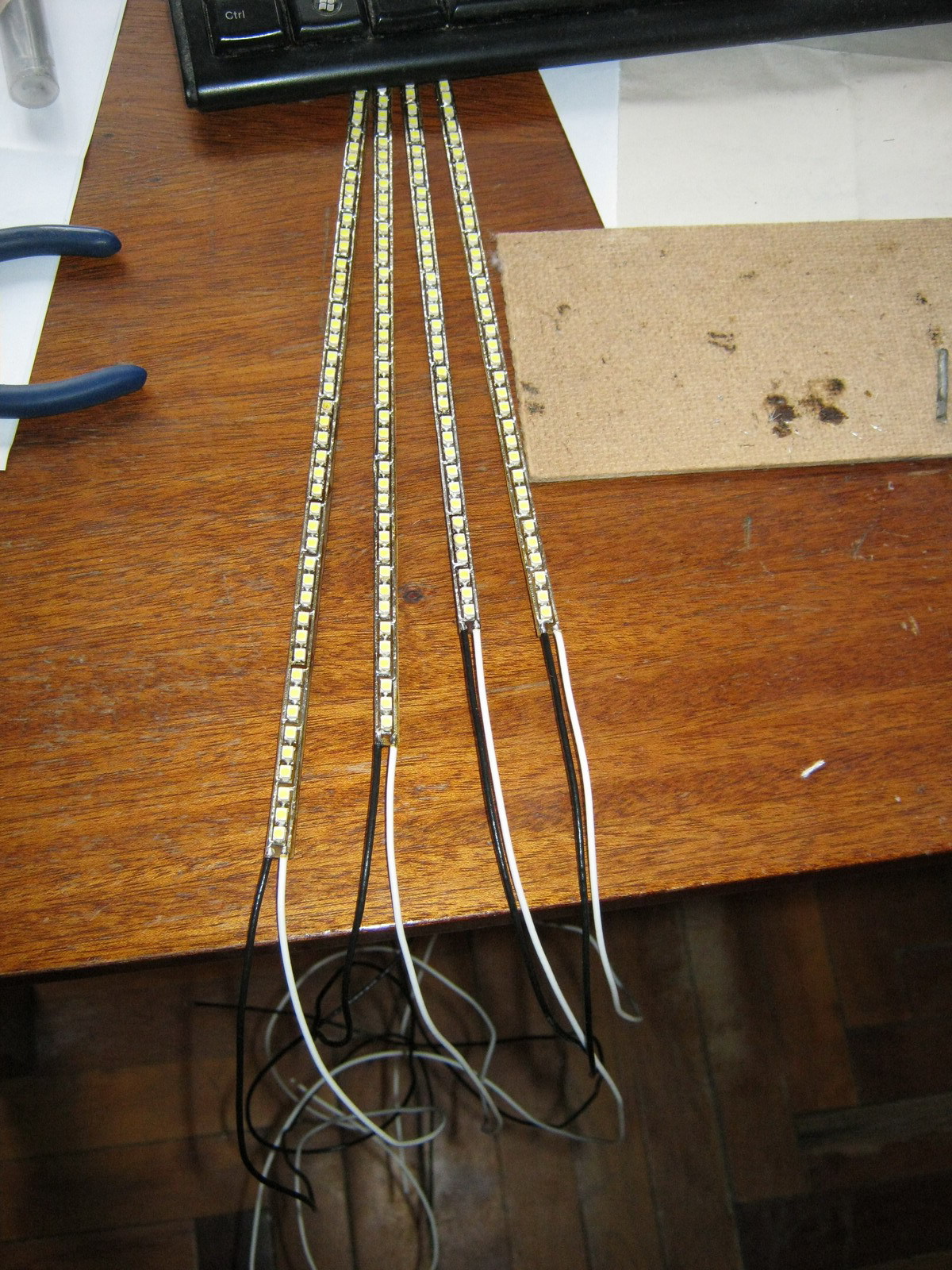
The strip is laid in two at the top and bottom of the wires to the edge of the monitor in the joint in the center:

The rated voltage of the LEDs is 3.5V (range from 3.2 to 3.8V), so the assembly of 3 consecutive LEDs must be powered by a voltage of the order of 10.5V. So the parameters of the regulator need to be recalculated:
The maximum voltage we need for a tape is 10.5V. Those. the maximum value of R2 = 1000 * (10.5 / 1.275-1) = 7.23 kOhm. The minimum voltage at which the assembly of the LEDs still somehow glows - about 4.5 volts, i.e. the minimum value of R2 = 1000 * (4.5 / 1.275-1) = 2.53 kΩ. R2, we consist of a variable resistor RV1 and multi-turn trimmer RV2. The resistance of RV1 is 7.23 kΩ - 2.53 kΩ = 4.7 kΩ, and the RV2 is set at about 7.23-4.7 = 2.53 kΩ and is adjusted in the assembled circuit to get 10.5V at the output of LM2941 with the maximum resistance of RV1.
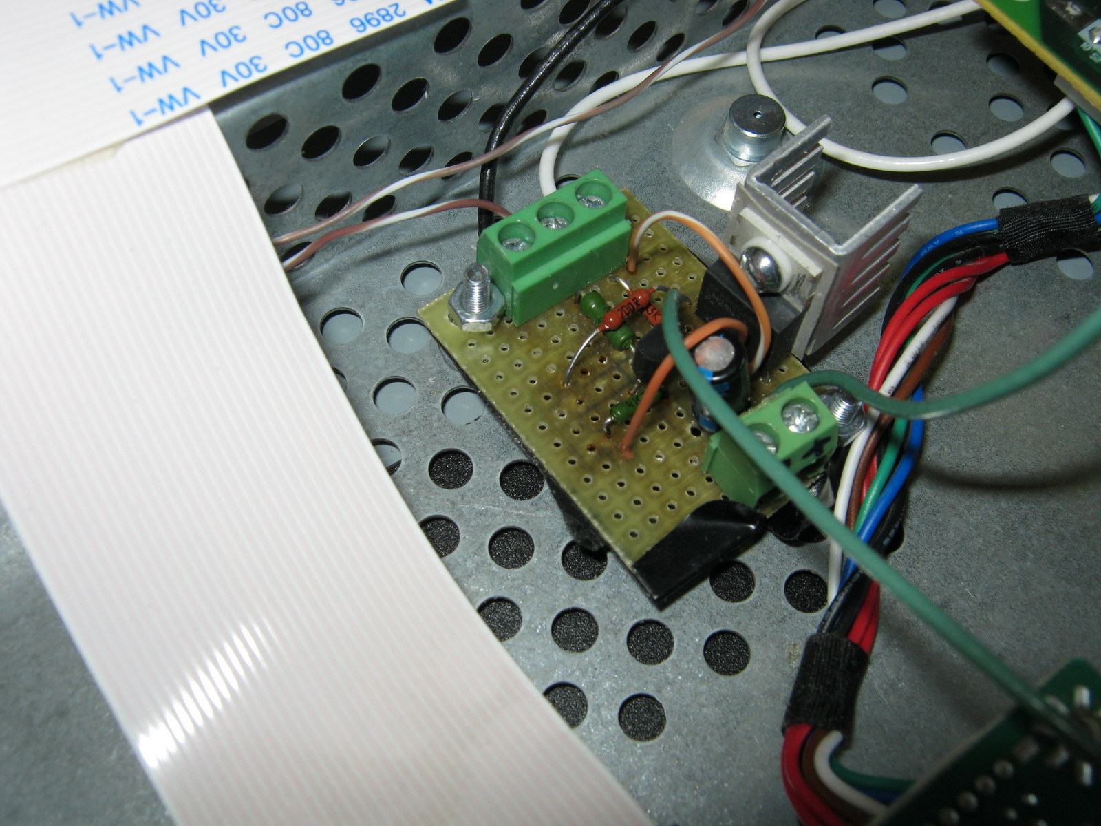
One and a half times more LEDs consume 1.2A of current (nominally), so the power dissipation on the LM2941 will be equal to Pd = (13.6-10.5) * 1.2 + 13.6 * 0.006 = 3.8 Watts, which already requires a more solid radiator for heat removal:
We collect, connect, get much better:

Advantages:
- High enough brightness (perhaps comparable, and perhaps even surpassing brightness of the old CCTL sublight)
- Lack of light cones at the edges of the monitor from individual LEDs (LEDs are located quite often and the backlight is uniform)
- Still simple and cheap control board
Disadvantages:
- The issue with the white balance in greenish tones did not dare.
- LM2941, albeit with a large radiator, but heats and heats everything inside the case
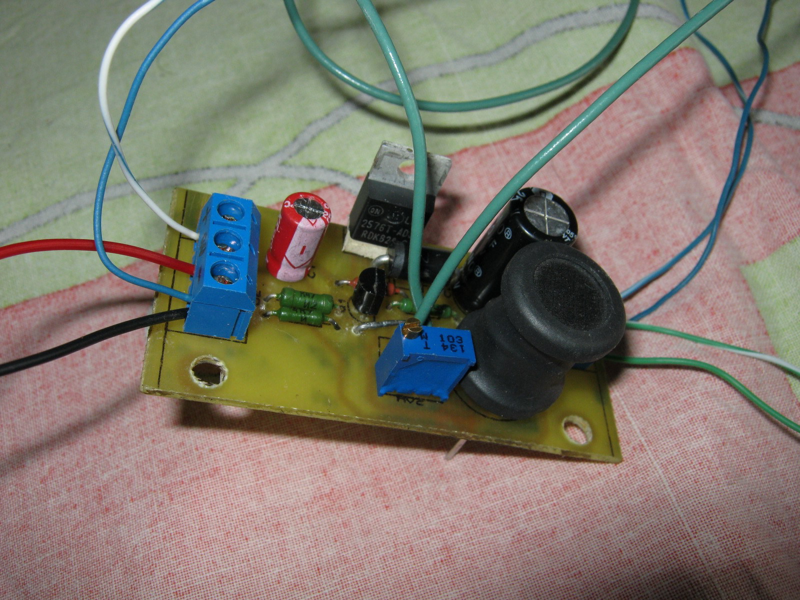
Control board based on the step-down regulator
To eliminate the heating problem, it was decided to assemble a brightness dimmer based on the Step-down voltage regulator (in my case, LM2576 was selected with a current up to 3A). It also has an inverted On / Off control input, so for matching there is the same inverter on one transistor:
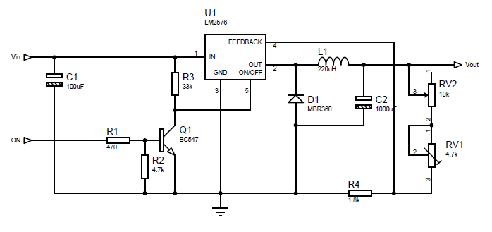
Coil L1 affects the efficiency of the converter and should be 100-220 µG for current in the load of about 1.2-3A. The output voltage is calculated by the formula:
Vout=Vref*(1+R2/R1)where Vref = 1.23V. For a given R1, you can get R2 by the formula:
R2=R1*(Vout/Vref-1)In the calculations, R1 is equivalent to R4 in the scheme, and R2 is equivalent to RV1 + RV2 in the scheme. In our case, to adjust the voltage in the range from 7.25V to 10.5V, take R4 = 1.8kOhm, variable resistor RV1 = 4.7kOhm and trimming resistor RV2 to 10kOhm with an initial approximation of 8.8kOhm (after assembling the circuit it is best to set its exact value by measuring the voltage output LM2576 with maximum resistance RV1).
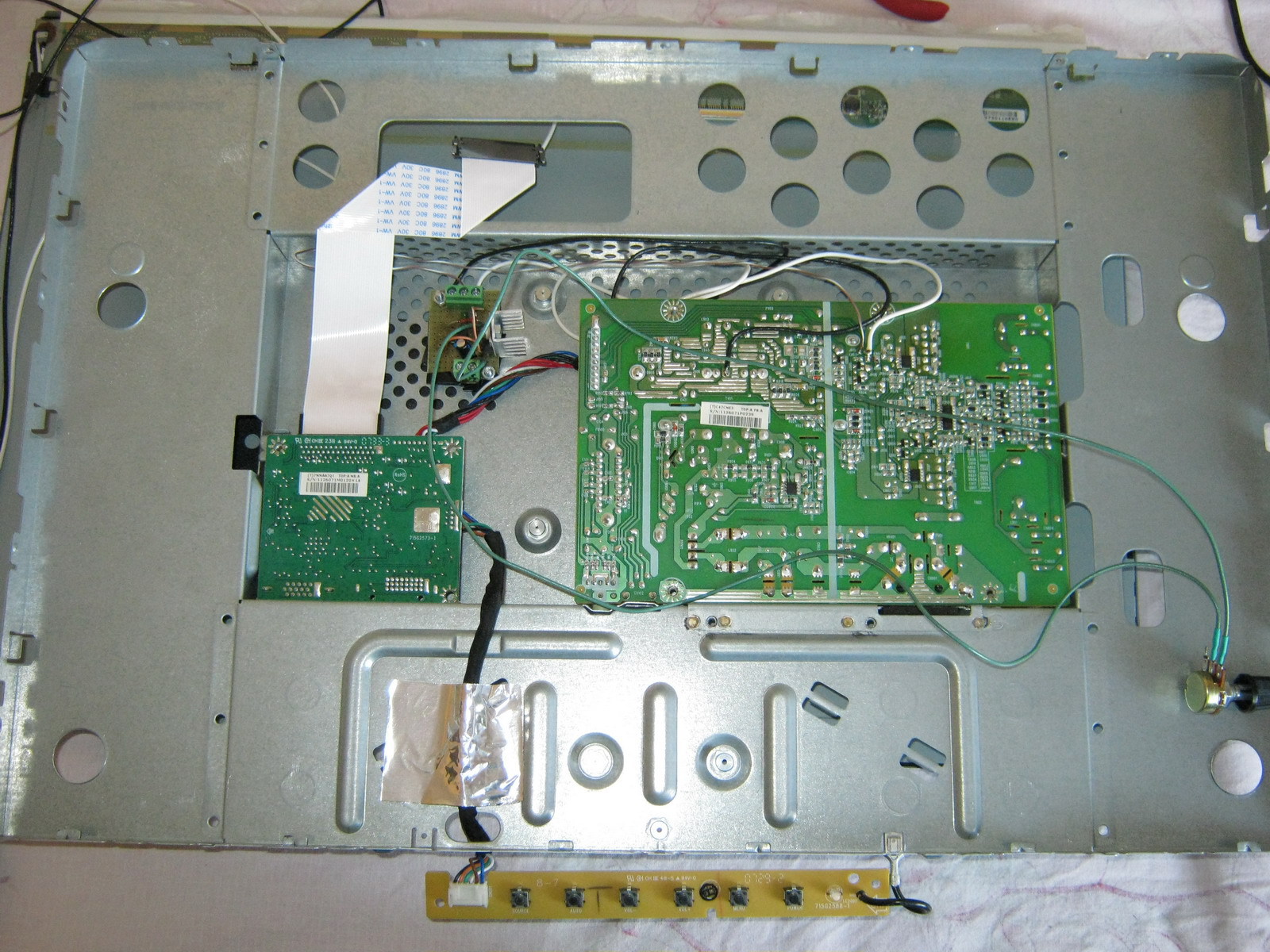
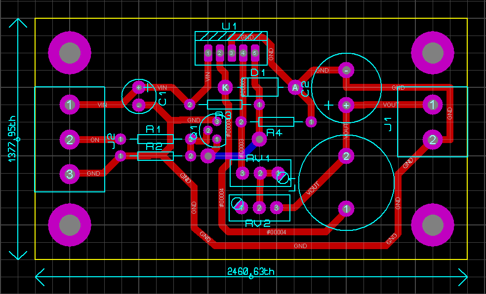
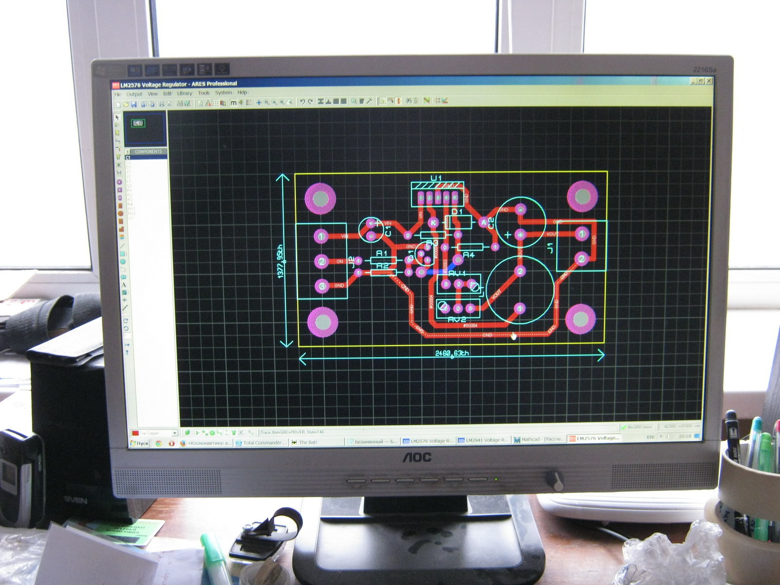
For this regulator I decided to make a board (the dimensions did not matter, because there is enough space in the monitor for mounting even an overall board):
Control Board Assembly:
After installation in the monitor:
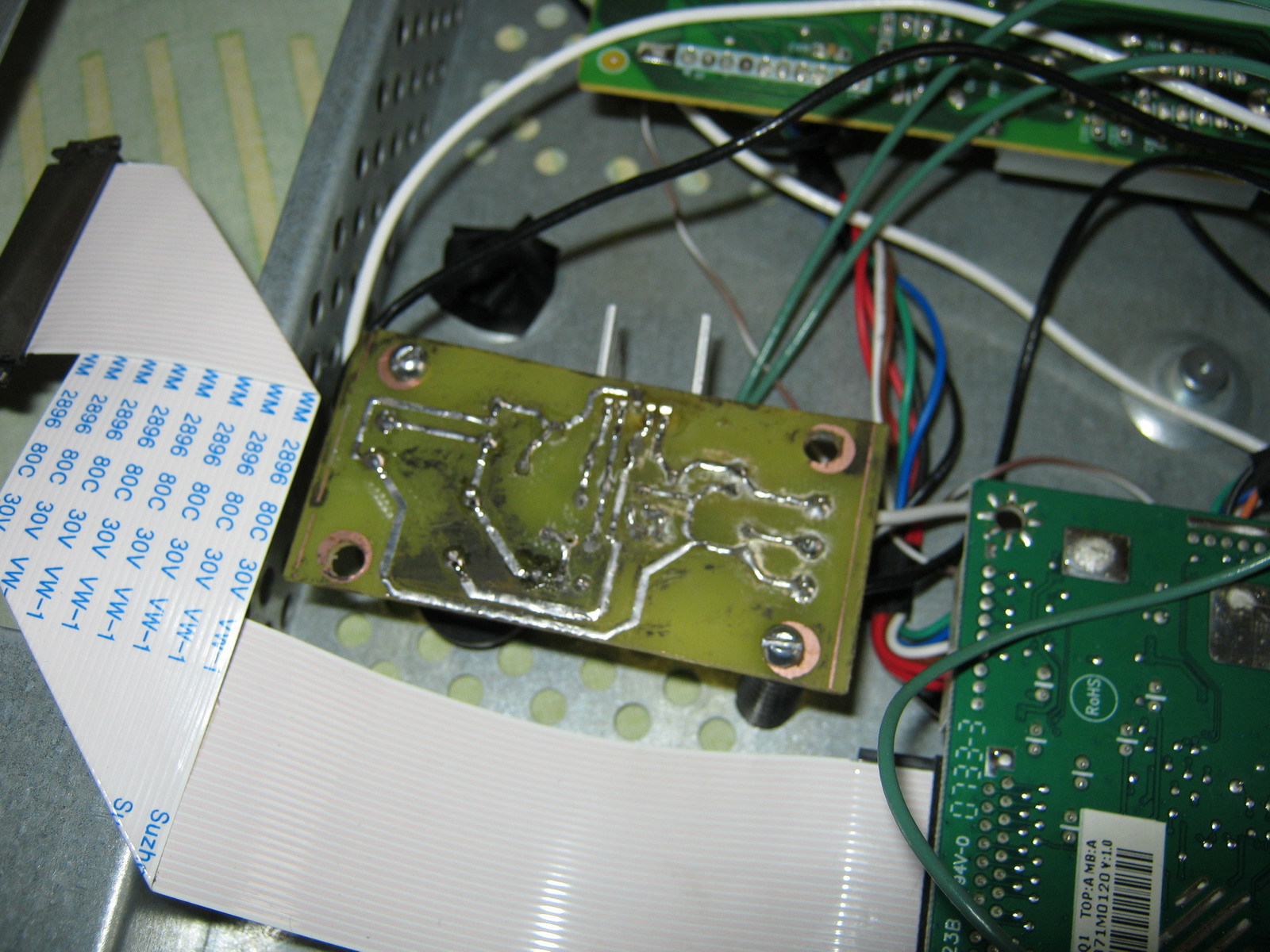
Everyone is here:

After the assembly, everything seems to work:
The final option:
Advantages:
- Sufficient brightness
- Step-down regulator does not heat and does not warm the monitor
- No PWM and therefore nothing blinks with any frequency
- Analog (manual) brightness adjustment
- There are no restrictions on the minimum brightness (for those who like to work at night)
Disadvantages:
- The white balance is slightly shifted towards green tones (but not much)
- At low brightness (very low), unevenness in the illumination of LEDs of different assemblies due to the variation of parameters is visible
Improvement options:
- White balance is adjusted both in the monitor settings and in the settings of almost any video card.
- You can try to put other LEDs that will not noticeably bring down the white balance
- To avoid uneven LEDs at low brightness, you can use: a) PWM (adjust the brightness using PWM by always applying a nominal voltage) or b) connect all the LEDs in series and power them with an adjustable current source (if you connect all 180 LEDs in series, you will need 630V and 20mA), then the same current must pass through all the LEDs, and each will have its own voltage, the brightness is adjusted by changing the current and not the voltage.
- If you want to make a PWM circuit for the LM2576, you can use the NAND circuit at the On / Off input of this step-down controller (similar to the LM2941 circuit shown), but it is better to put a dimmer in the gap of the negative LED wire through logic-level mosfet
Under the link you can download:
- AOC2216Sa Service Manual
- LM2941 and LM2576 datasheets
- Regulator circuits on the LM2941 in Proteus 7 format and PDF
- PCB layout for LEDs in Sprint Layout 5.0 format
- Scheme and layout of the controller board on the LM2576 in Proteus 7 format and PDF
Source: https://habr.com/ru/post/214993/
All Articles