Using DSP SB Live! for the benefit of radio amateurs (KX Driver's) - Part [1/2]

Experiments on sound processing hardware SB Live and their possible use for work on the air. The note includes instructions for the use of alternative drivers KX-Project, examples of applications and conclusions on the possibility of real use. The period of writing the article for 2006-2007 was posted on the page of the now-defunct collective radio station ( RK3MXH ). Authorship is mine.
The article can be useful not only to radio amateurs, but also to music lovers, musicians and other people who are not indifferent to the quality of sound.
There is a lot of text and pictures under the cut.
')
Content
Introduction
1.1.Kx-project - alternative drivers
1.2.The most favorite features and what was achieved
2. Installation
3.First problems after installation and their solution
3.1. Where did the sound go?
3.2. Missing MIDI sound
3.3. Strange work of the programs working with line / microphone inputs (sound recording, program DSP)
4.Management and configuration
4.1.KH Mixer - Master
4.2.KH Mixer - Inputs and Outputs
4.3.KH Mixer - Recording
4.4.KH mixer - AC97
5. More detailed instructions
6. Description of DSP objects
7. Examples of use
7.1. Simple wiring diagrams
7.2. Record signal
7.3.Work with SpectraLab
7.4.Working with software DSP
8. Examples of use for amateur radio
8.1.CW - filter
8.2.SSB - filter
8.3.Notch - filter
8.4. Microphone signal processing
8.4.1. Equalizer
8.4.2. Reverb
8.4.3.Other
Continuation
Introduction
Many radio amateurs use computers in their necks. Basically, of course, for keeping a hardware log. But with increasing productivity of personal computers, the scope of their application began to expand. Radio amateurs began to use PCs to process the received signal and form the signal for transmission ( digital forms of communication ). There are also filter programs (DSP filters) that “emulate” the operation of real filters, allowing you to quickly change the bandwidth, suppress noise, etc. All these programs for signal processing use the computing power of the PC's central processor, which requires a certain performance from it. The sound card is used only as a DAC / ADC. No hardware capabilities of sound cards are usually used.
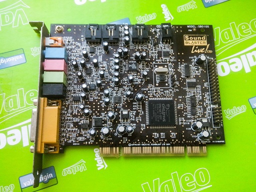
A series of sound cards from Creative Labs has always been pleased with its quality. Starting with the SB Live model and above - the cards are equipped with special signal processors (DSP) EMU10K1 (various versions of SB Live, Audigy) and more advanced EMU10K2 (Audigy2). Drivers of standard delivery to these cards amazed by the number of sound settings (equalizer, reverb, etc.), which were realized by the hardware of the card itself. The hardware implementation of sound effects made it possible to achieve an excellent result with minimal system loads (I still remember the Quake 2 experience on a Pentium-166 computer with an SB Live card and 3D sound). Since then, I have finally “sunk down” on SB Live! and still use ( unfortunately, no longer the case ).
Having received the maximum of possibilities, service and pleasure from listening to music with the help of this board, I began to think about using the hardware features of SB Live! for sound processing when working on the radio. It turned out that in the set of filters and equalizers there are Notch filters (to suppress a certain frequency) and BandPass (to select a specific frequency), a LowPass filter. A HighPass filter (only passes frequencies above a certain level), and a LowPass filter (only below a certain frequency). LowPass, HighPass and Notch filters can be used when working with SSB, and BandPass for telegraph reception. There are also many other filters that can be used both to process the transmitted signal and to form its own unique signal for transmission.
The volume of the material presented was quite large, as I tried to describe everything as clearly as possible and with a large number of examples. I generally think that the more examples, the easier it is to understand. Also, one of the reasons was the fact that already three people I knew, having tried KX drivers, refused to use them (for someone, there were too many possibilities, someone did not understand MIDI playback and recording). Therefore, the installation of KX drivers will first be considered; then the first possible difficulties and problems that the user and their solution may face will be described; after that, controls and settings will be considered; Below, we will consider several examples of DSP settings for listening to sound; signal recording; work with Spectra Lab and software DSP; then go examples of use for amateur radio purposes; then the recordings from the air will be provided with the DSP processing of the sound card. In the last but one part, I will look at the problems and limitations when using the board. At the end of the presentation I will try to draw conclusions about the usefulness of using the SB Live! for amateur radio purposes.
I hope that after reading this article, there will be more both users of sound cards with EMU10k1 / k2 chips and users of KX drivers, and the information in the article will teach the basic principles of their use. If after reading any questions remain, it will be interesting to me to try to solve them with you.
Although these cards already go down in history, but they are available on the secondary market, someone has it on the shelf. The card can be a pleasant surprise for the musician. It works well with ASIO, and at the same time with the standard Windows sound output (which is not on my current USB sound card), it has low latencies.
1.1.Kx-project - alternative drivers
The next surprise from the cards of this series were alternative drivers, written by a group of developers headed by Eugene Gavrilov. They allowed to use the hidden features of the SB Live! Sound processor. The driver complies with the WDM (Windows Driver Model) specification and can work in the following operating systems: Windows XP, Windows 2000, Windows 98 (Second Edition only) and Windows Me.
When installing the driver, the following functions become available:
- Record and play sound in Windows MME-programs;
- recording and playback of sound in ASIO-programs (Steinberg Cubase and Nuendo, Logic Audio);
- the use of an internal processor for processing effects of individual tracks of a multi-track project, as well as of the entire audio and MIDI stream entering the output of the sound card;
- 16 independent buses used for internal switching of signals and effects; - from four to eight (depending on the sound card used) independent analog outputs;
- MIDI synthesizer, "understands" the format of SoundFonts;
- DirectSound 2D;
- DirectSound 3D (software simulation, works only in the mode with two loudspeakers);
- complete AC97 I / O control;
- software AC-3 decoding;
- DSP microcode change (for engineers and developers);
- change the appearance of the interface using "skins".
In addition, all internal connections (effect blocks, signal paths from the input of the board to any of its outputs and buses) can be programmed using a very simple and intuitive interface. [1]
1.2.The most favorite features and what was achieved.
The signal from analog inputs from software sources can be processed in the DSP with various effects. An arbitrary order of effects can be selected. The board is presented to the system not as a single device, but as 4. The front stereo output and the stereo output to the rear speakers are presented as separate outputs and can be used arbitrarily.
Here are some examples:
1. You can run two sound playback programs (for example wimamp). One is set up on the first virtual card, the second is on the second. Then send signals: one to the front exit, the second signal to the rear personnel. And if you connect some headphones to the green connector on the card, and others connect to the black one, then two people can, without interfering with each other, listen to different music.
2.If it is required from time to time to reproduce the sound then on the headphones, then on the speakers, then you constantly have to “poke” the connectors (or use any external splitter). In the case of SB Live, you can connect the speakers to one stereo output, and the headphones to another and “split” the signal into two outputs. Plus, the signal for speakers and headphones can be processed differently (because the frequency response is different, and in the headphones I would like to hear, for example, echo).
3. The signal from the card input (mic / line / cd) can be processed in real time and sent to the output. For example, a signal from a tape recorder (processing by an equalizer), from a microphone (equalizer, limiters, compressors, echo), from an electric guitar (equalizers, limiters, compressors, distortion, flangers, echo), from a TRANSFER! (Equalizers, notch and CW filters).
2. Installation
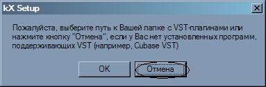
To install the drivers, they need to be “downloaded” from the developers site www.kxproject.com . There are also instructions for use, including in Russian.
In general, installing the driver should not cause difficulties and problems.
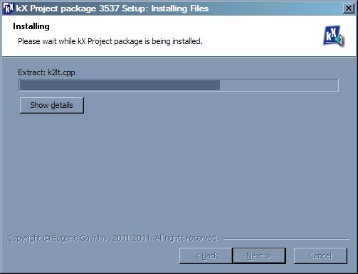
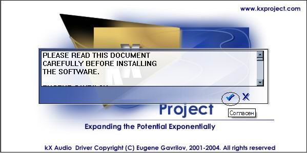
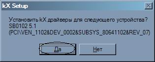
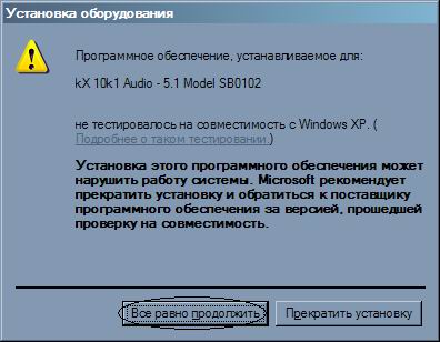
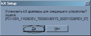
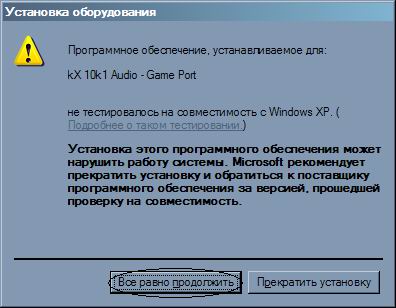
Run the exe file with the installer and follow the instructions.


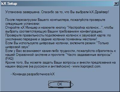

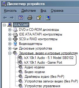
Installation is complete. To check, you can go to the device manager.


An item to start the mixer is added to the taskbar.
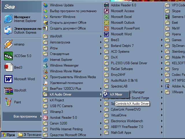
After restarting the computer or running Kx mixer in the system tray (near the clock), the KX icon will appear.

If you double-click the icon, the main window of the system mixer opens with tabs and buttons for controlling the map.
Clicking the right button on the tray icon will bring up a context menu with additional settings.

Installation is complete. We can congratulate ourselves on the beginning of a long journey in studying the management of a complex product called the KX Project.
3.First problems after installation and their solution
Additional card management options also result in certain difficulties. A large number of settings scares. Because of this, some users do not fully understand the possibilities, abandon the Kx-drivers in favor of the standard.
3.1. Where did the sound go?
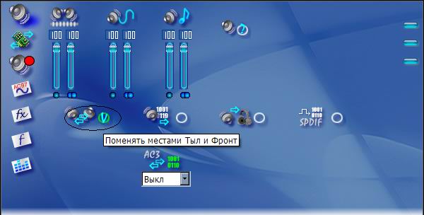
Immediately after installation, it turns out that the sound stops playing. For example, WinAmp plays, but there is no sound. This is due to the fact that by default the front and rear columns are swapped. This is due to the fact that for output to the rear speakers the card has a higher-quality DAC. In order for the sound to "appear" - you need to either reconnect the speakers (headphones) from the green connector to the black (rear). Or, in the settings, uncheck "Swap Front and Front".
3.2. Missing MIDI sound
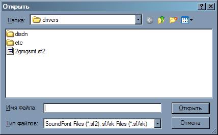
MIDI synthesis does not work immediately after installation, because no instrument bank is loaded by default. Recording professionals have different instrument banks and load them as needed. But if there is nothing suitable at hand or you simply do not know what a bank of tools is, then there is one way out. On Windows, in the \ system32 \ drivers folder there is a 2gmgsmt.sf2 file, which is the simplest tool bank. It can be used. To do this, open the Kx SoundFont tab, click + “Download SoundFont”
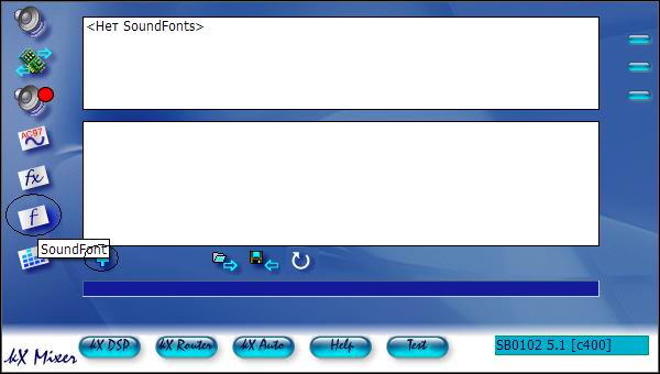
and select a file, for example c: \ windows \ system32 \ drivers \ 2gmgsmt.sf2
click on the check mark


Bank successfully loaded. Now you can listen to karaoke, ringtones, etc., that uses MIDI-sound.
3.3. Strange work of the programs working with line / microphone inputs (sound recording, program DSP)
Usually, the selection of the signal source for recording occurs on the system mixer through the “recording” tab (System Mixer-> Options-> Properties). After installing the Kx drivers, it turns out that a different approach is taken here. Moreover, it may turn out that a signal from the input is heard in the headphones, but it is not recorded. Even more strange programs work with the processing of sound from the inputs in real time, which receive the signal, process it and output to the speakers. They either do not receive a signal at all, or when, in the process of experimenting with the settings of the board, they still manage to file a recording, they start choking on the echo of their own signal. This is due to the peculiarities of sound recording in the Kx-system. As a lyrical digression, it is worth noting that the Kx card management system is intended for recording professionals (for whom all these nuances are understandable, unlike me) and therefore appropriate management techniques are used.
4.Management and configuration
Next will be considered techniques for working with controls. The system mixer contains only basic controls. KX system controls are dealt with at default settings. The KX Rooter element in this article is not considered, because of the insufficient iq author of this article. Element KX Editor allows you to edit directly the code of digital filters. Those who know how to do this can not read this article at all, because nothing new will be found. The KX Automation element, as far as I understand, is used to control filter parameters through MIDI devices. Not studied in more detail for the same reason as the KX Rooter. KX Remote is not implemented in the drivers (yet). KX SoundFont allows you to load MIDI Bank (s), discussed above.
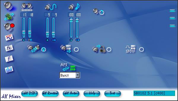
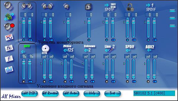
4.1.KH Mixer - Master
Double clicking on the KX icon in the tray or selecting the right mouse button from the context menu of the KX Mixer item will open the mixer control window. By default, the “Master” tab opens, in which the overall output level and the separate PCM (all audio program outputs) and MIDI levels are controlled.
Buttons located on the applet along with the faders allow you to enable and disable the digital and analog outputs of the board and, interestingly, to swap the front and rear monitoring channels. By default, by the way, after installing the driver, the main channels of monitoring become precisely the rear channels, so do not forget to switch the minijack that your monitor system is connected to from the front output of the sound card to the rear one. This is done in order to use for monitoring a higher quality unbuffered rear channel output. However, if this does not suit you, you can always remove the “daw” under the inscription “Swap front and rear”, which stands there by default, and monitor it as before. [1]

The rows of buttons on the left and bottom are always displayed regardless of the selected bookmark:
On the left, all the way down are the buttons: “Master” with basic settings; “Inputs and Outputs”, “Recording”, “AC97 Codec”, “Effects”, “SoundfFont”, “Analyzer”.
From the bottom, from left to right, there are buttons: “KX DSP”, “KX Router”, “KX Automation”, “Help”, “Speaker Check”.
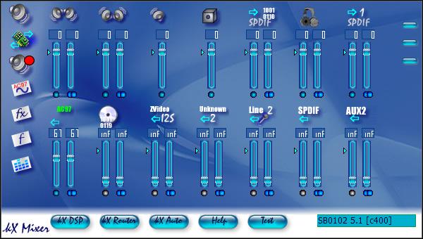
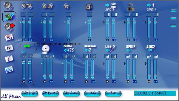
4.2.KH Mixer - Inputs and Outputs
The “Inputs and Outputs” tab contains controls for monitoring the separate front and rear channels, the digital SPDIF output level and the headphone output (which can be used for the subwoofer output and the center channel - if they exist, of course).
These controls are available using SB Live! and Value, with other boards the picture can be very different - additional digital and analog outputs appear. I note that the position of the knobs located on this tab does not affect the level of the recorded signal, but only regulates its volume in the monitors during recording and, of course, playback. [1]
4.3.KH Mixer - Recording
The controls on the Record tab allow you to set the desired signal level for recording from each of the available inputs. The level of the signal coming from the line and microphone inputs is set by the AC97 knob (it's easy to guess that there are several more hiding behind this fader, a little later about them). There are also two faders that allow you to adjust the recording level of the effect separately (by default, reverb and chorus), if you suddenly need to record an audio or MIDI signal from the output of the board, processing it with the existing effects. [1]

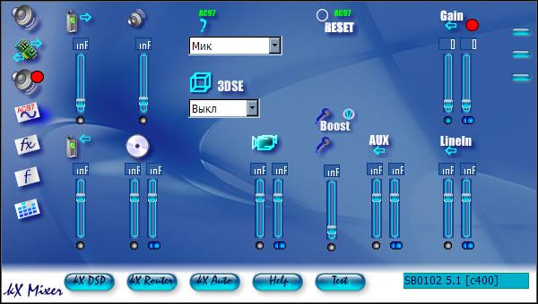
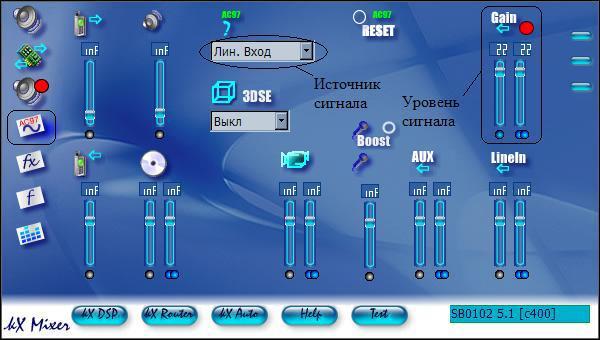
4.4.KH mixer - AC97
The "AC97-Codec" page (Audio Codec 97) controls the outputs and inputs of the AC97-codec.
Outputs:
"TAD Out" - output to an external telephone device (mono). It is a four-pin connector located directly on the board and labeled “TAD”.
"PCSpkr" - mono output to the PC-speaker. Located there on the board.
Inputs:
“TAD In” is similar to TAD Out, just the opposite: input from an external device.
"Analog CD-in" - an input for connecting an analog CD-ROM output. Do not confuse it with an electrical input for recording from a digital output of a CD-ROM, the regulator of which is located on the above-mentioned “Record” tab.
"Microphone" - a mono input for connecting a condenser microphone.
"Video input" - stereo audio input for recording from an external video source. Most KX compatible sound cards are missing.
“AUX” is an additional input located directly on the board and labeled “AUX_IN”.
"Line In" - line input; main input used for recording. Three-pin minijack located on the back side of the board.
Additional controls:
“Reset” - reset all mixer settings to their original state.
“Mic Boost” - increase the signal from the microphone input by 20 dB.
“3DSE” is a conditionally useful function for controlling 3-D sound modes. The following values are available: "Off", "Little", "Medium", "Many".
"Source AC97" - the source of the record.From the entire set of inputs, recording can be made only from one of them - the one that will be selected from this drop-down menu. The exception is the case when the “StereoMix” mode (or “MonoMix”) is selected. Then the sum from all inputs plus the output PCM signal is recorded - the system audio output signal. A detailed block diagram of the sound card and the signal paths are presented in the following figure. Connections formed when the “StereoMix” mode is turned on are indicated by a dotted line. [1]
5. More detailed instructions
In the process of writing, by the way, I was once again convinced of two proverbs / sayings: “don't reinvent the wheel” and “if nothing helps, it's time to read the instructions”. Moreover, I finally managed to get an official instruction in Russian.
 kxhelp_en.chm
6. Description of DSP objects
Please read the above instructions or at least the “KX DSP” chapter in order to know the purpose of the rectangles in the driver's internal connections window.
So.Consider the standard configuration of driver connections.
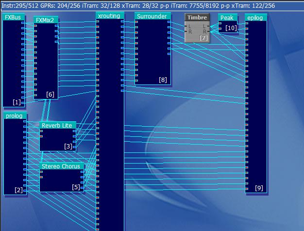
The main elements of the scheme:
1. Objects from which the input signals originate (physical inputs, virtual streams generated by a computer);
2.Router;
3. Object to which the processed signal goes (physical outputs, ASIO);
4. Objects of signal processing (effects);
1. Input signals.
- internal signals generated by the operating system: wave (Wave) signal - sound reproduced by applications such as WinAmp, SoundForge and others; MIDI synthesizer outputs when playing mid files or when running other programs that receive sound using a sound card synthesizer (CakeWalk).
- External signals to the physical inputs of the sound card: line input, microphone input, input from a CD-ROM.
Internal input signals in the internal circuitry coming out of the FXBus object
 | FXBus — '', DSP. , -, ( ). : (Wave) — FXBus 0 FXBus 1. MIDI — FXBus 02 FXBus 03. Surround (AC3) DirectSound 3-D — FXBus 04 09.[2] , . 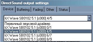 « » "...0/1". 0 1 FXBus. «»: "...4/5", "...6/7" "...8/9". . . ( WinAmp' , ) ( .). |
Prolog
 | . , ( , , ). — , « » kX . , , ASIO. 10k1 (7 ): In0/1: AC97 — / In2/3: CD — / In4/5: I2S — / In6/7: Coaxial / Optical — / (LiveDrive) In8/9: Line 2/mic 2 — / (LiveDrive) In10 / 11: Coaxial / Optical - left / right (LiveDrive / daughterboards) In12 / 13: AUX 2 - left / right (LiveDrive) [2] |
2.Router (signaling machine)
Routing
 | The routing object (routing) mixes all incoming signals and distributes the sends to the correct outputs (effects, recording, etc.). Routing mixes prolog inputs with FXBus signals and routes them to various outputs, depending on your mixer settings, including front, rear, center, subwoofer, headphones and, not least, recording settings (but not ASIO recording). [2 ] In other words, this object performs all manipulations with the received sound, controlling its redirection to the physical outputs, to the recording or to the ASIO. When working with faders on the KX Mixer tabs, we influence this object. In principle, it is possible to directly connect the outputs of the objects of the input signals with the inputs of the object of the physical outputs of the card, without using the Routing object, and obtain sound at the output. But in this case, the system mixer and the KX Mixer will not work. |
3. Object to which the processed signal goes (physical outputs, ASIO);
 | Epilogue is the physical output of your sound card, including recording inputs and 16 inputs to ASIO recording. Usually, all the outlets are connected, but in some cases (for example, installing two speakers) you need only one pair of cables that connects to the outlets to the speakers. The connections to the recording are made according to the settings of the kX mixer window settings tab. Please note that these settings only affect the actual recording, not what you hear. Also, it does not affect the ASIO entry. The last 16 channels are the inputs to the ASIO recording. They are connected in stereo pairs (even / odd equal left / right) when the ASIO recording is set to stereo recording. You can connect to these inputs any output of any object. [2] Out0 / 1: Analog front left / right output; Out2 / 3: Main SPDIF output left / right; Out4 / 5: SPDIF1 output left / right; Out6 / 7: SPDIF2 output left / right; Out8 / 9: Analog rear left / right output; If the checkbox “Swap Front and Front” is checked in the settings, then the names of these inputs (0, 1, 8 and 9 will be in square brackets signed [swapped]) Out17: Analog Center; Out18: Analog subwoofer; Asio0..Asio15: inputs to the ASIO record; |
4. Signal processing objects (effects)
With the help of these elements we will be able to carry out various manipulations over the sound.
| Object image | Object Management Window (click to enlarge) | Purpose | Description |
|---|---|---|---|
| Main | |||
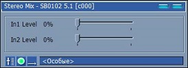
 | 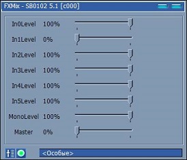 | Mixer. | Stereo mixer for 5 inputs with one output |
 |  | Mixer. | Stereo mixer for 5 inputs with two outputs. |
 |  | Mixer. | Stereo mixer 2 inputs with one output. |
 | 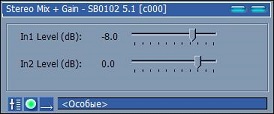 | Mixer. | Stereo mixer 2 inputs with one output (signal level in dB). |
 | 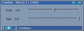 | Crossfader. | Allows you to make a smooth transition from one signal to another (feel like a DJ). Gain adjusts the gain of the signal. |
 |  | Stereo> Mono. | Monomix to convert stereo signal to mono. |
  |   | Balance. | The object to adjust the balance (x2 sounds louder). |
 | 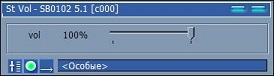 | Volume (stereo). | Stereo signal level control. |
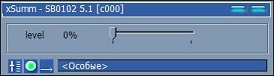
  |   | Signal gain (dB). | Gain control in dB. GainHQ allows you to separately adjust each channel. |
 |  | Volume (mono). | Mono level control signal. |
 | 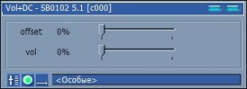 | Volume (mono +). | Mono signal level control + DC (apparently constant current). |
 |  | Level indicator | Displays the level of the input signal. It can be displayed both vertically and horizontally. Very useful facility. Allows you to control the signal level in parts of the circuit that can not be controlled by ear. Allows you to adhere to the level of 0 dB in all links of the circuit. |
 | - | Phase rotation | Expands the phase of the signal by 180 degrees (determined empirically: when adding the original signal with the signal that passes through this object - silence is obtained). |
 | - | Adder | Add up three beeps. |
 |  | Adder | Folds stereo and mono signals, it is possible to adjust the signal level. |
 | - | Divider | Divides the signal by 4. |
 | - | Multiplier | Multiplies the signal by 4. |
 | - | XOR | Assignment failed to determine. |
| Filters and equalizers | |||
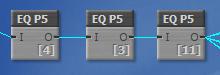
 | 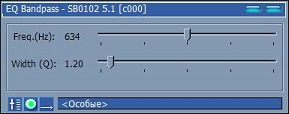 |  EQ Pandpass (FSC). EQ Pandpass (FSC). | A filter allowing only the selected frequency with the specified quality factor (aka CW filter). |
 | 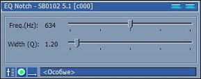 |  EQ Notch. EQ Notch. | Filter, leaving a certain frequency with the specified quality factor (aka Notch filter). |
 |  |  EQ Highpass (high pass filter). EQ Highpass (high pass filter). | A filter that only passes above a certain frequency with the specified goodness. |
 | 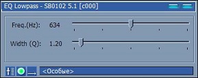 |  EQ Lowpass. EQ Lowpass. | A filter that passes only below a certain frequency with the specified goodness. |
| There is also a high-pass and low-pass filter, a 10-band equalizer. There are also additional ufxsetup36 filters. A very remarkable set of 10-band equalizer, parametric and other above-mentioned filters with a convenient and intuitive interface. | |||
 |  | Equalizer. | 10 band graphic stereo equalizer. |
  | 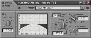 | Equalizer (mono / stereo). | Parametric stereo equalizer. Type switches: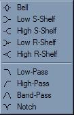 |
  | 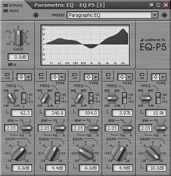 | Equalizer (mono / stereo). | Parametric 5-band stereo equalizer. Types are switched. (Just a fairy tale!) |
Only standard and, in my opinion, components were shown here. With the rest, I think it will be interesting to figure out for yourself: APS Pitch - frequency shift, compressors, reverbs, signal and noise generators, Decimator for converting bit depth and audio sampling (1-32 bits, 1-48000 Hertz), and so on.
7. Examples of use
Below are the first simple schemes, and then examples of using KX drivers for various applications.
7.1. Simple wiring diagrams
One to one. We connect the outputs of the Windows software sound from the output of the FXBus object to the physical output of the card. As a result, we have sound on the front speakers. This is the minimum working scheme.
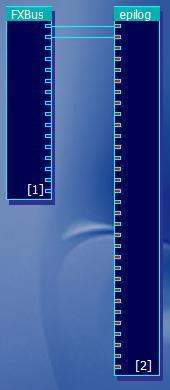
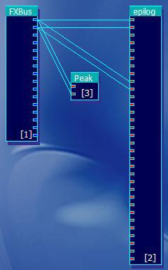
We connect the outputs of the Windows software sound from the output of the FXBus object to the physical outputs of the card. As a result, we have sound on the front and rear speakers. The signal level can be viewed using the Peak object.
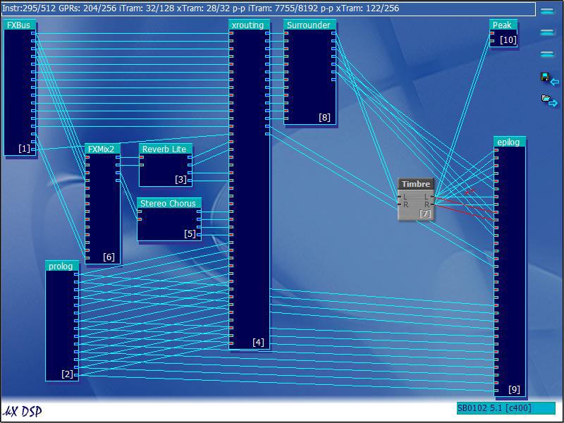
We connect the outputs of the Windows software sound from the output of the FXBus object to the physical outputs of the card. As a result, we have sound on the front and rear speakers. The signal to the front speakers passes through a 10-band graphic equalizer, and the signal to the rear speakers passes through the tone control. Also added signal level indicators. The picture shows the level indicators and controls the equalizer and timbre.
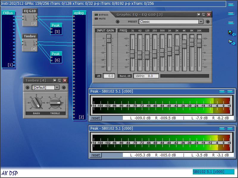
We connect the outputs of the Windows software sound from the output of the FXBus object to the physical outputs of the card. As a result, we have sound on the front and rear speakers. The signal to the front speakers passes through a 10-band graphic equalizer, and each channel can be tuned separately. The signal to the rear speakers - through the tone control. Also added signal level indicators. The picture shows the level indicator and controls the equalizer and timbre.

Making changes to the standard scheme for sound output to the rear and front speakers. The red lines indicate the connections that need to be created — the lines to the physical outputs of the Analog Rear Left / Right card. Crossed lines - lines that will disappear after the connection.
If you try to add a 10-band equalizer to the standard circuit, an error about the lack of resources will be displayed and, as a result, the filter will not work. In order to free up some resources, you can remove any of the unused objects, such as Stereo Chorus and Reverb Lite. After their removal, it will be possible to construct a circuit in which the output to the rear speakers passes through a 10-band equalizer, and to the front speakers through a tone control.

Add some volume to the signal using the Reverb R component.

The basic principle, I think, is clear. Schemes using the rest of the objects I leave for self-study :)
7.2. Record signal
In order to record a signal, you must first select the source (on the “Record” tab): physical or software:

If the recording will be carried out from the physical input, then on the “AC97-codec” tab select the source:

And if you choose stereo or mono mix, then the recording will be made from the internal program sound, which can be a mixture of all signals: both program and physical.
If there is a need to monitor the recorded signal through the columns, then from the relevant sources you need to select the appropriate level on the “Inputs and Outputs” tab:
Attention! If you turn on monitoring of the signal from the AC97, and mono or stereo mix is selected as the source, the playback signal will again and again go to the AC97 input and play again. Thereby a “ring” will be formed. If the gain level is less than 0 db, then an echo will be observed, and if it is greater, self-excitation will occur and the signal will reach a maximum after a certain time. An unpleasant loud sound will be heard.
Further work in the recording programs does not differ from standard drivers.
7.3.Work with SpectraLab
In the standard configuration, the sound reproduced by the windows programs will be analyzed by Spectralab without additional settings of the kx drivers. But there are two options for work.
1. Analysis of the signal from software sources. If we go into kx-mixer on the record tab, we will see the positions of the faders “Record Level Wizard”, “Wave Record Level”, etc. in a non-zero position. The control faders of the physical inputs are set to inf (disabled). In this case, the Wave signal (generated by the programs), as well as signals from other sources (if any) will go to the input of sound recording programs.

Thus, the signal output by the winamp program will be played through the monitor systems and, falling on the recording channel, will be analyzed by the SpectraLab program.
In the figure, a circle outlines the lines along which the signal reaches the RecL / RecR inputs.

2. Analysis of the signal from the physical inputs. In order to analyze a signal from a physical input (for example, a linear one), it is necessary to record a signal from the corresponding input. To do this, first select the signal source (for example, “Input. Input”) on the “AC97-codec” tab, set the gain level using the “Gain” fader.
Then, on the “Record” tab, set the “Record Level from AC97 Codec”.

After this program SpectraLab will begin to analyze the incoming signal. If there is also a need to listen to the input signal, then on the "Inputs and Outputs" tab you need to set the required level using the "Input AC97" fader.
You can also analyze audio from program sources using the signal from the AC97, if you select mono or stereo mix as the source.
7.4.Working with software DSP
Work with software DSPs will be discussed on the example of the program DSP Filter Ver1.11 JE3HHT 2000 .
Software DSPs take a signal from a source that is selected for recording, processes, and programmatically reproduces. In order to do this in the KX drivers, you need to do the following:
- On the “AC97-codec” tab, select the “Input Line” source and the signal level (Gain).
- on the “Record” tab, select “AC97” as the signal source and select the required level. It is MANDATORY to set the “inf level” to the “inf” position of the WAVE recording level so that the signal processed by the software DSP does not reach its input again (forming a ring).
- on the “Inputs and Outputs” tab, set the “Input AC97” fader to the “inf” position so as not to hear the original unprocessed signal over the processed DSP.
Since the processing is carried out programmatically, using the SpectraLab program, it is not possible to view the results of the operation of the DSP software. But there is nothing to worry about, because DSP Filter has its own spectrum analyzer.

8. Examples of use for amateur radio
On the KX DSP window, we see a certain scheme with which the inputs and outputs are connected. In the "middle" are the objects of signal processing. In the examples below, the signal from the line input will be processed and sent to the output. Schemes will differ only in sound processing chains. The main part will always be the same. Therefore, in the examples the whole scheme will not be given.
The signal processing circuit from the physical inputs can be performed in two ways:
1. Making changes to the default schema . In this case, the circuit will need to be corrected as follows: the signal processing facility (s) is included in the gap of the lines going from the prolog object (AC97 Left / Right) to the xrouting object; and to see the result of signal processing in the SpectraLab program, you need to send a signal from the output of the processing object (s) to the epilog (RecL / RecR) recording input.

2. Creating the minimum required scheme. In this case, the DSP circuit will contain only the object of receiving the signal from the physical input, the object of signal processing, and the object of outputting the signal to the physical outputs (and to the analysis). This allows you to save infinite resources when processing schemes that require large amounts of memory DSP.
Connections are made as follows: the signal from the prolog object (AC97 Left / Right) is sent to the signal processing facility (s), and then to the epilog object (Analog Front Left / Right, Analog Rear Left / Right and RecL / RecR)

Level adjustments and fader positions required for operation on tabs:
- AC7-Codec - select the required input and gain level by it
- Inputs and Outputs - fader "Input AC97" adjusts the level of the processed signal. Moreover, with these connections, this fader affects both the signal level that we hear through the monitor systems and the signal level that will be sent to SpectraLab for analysis.
- Recording - using the “ Record Level Master” fader, we can change the level of the signal going to SpetraLab for analysis. The fader “Record level of the AC97 codec” must be set to the “inf” position (!!!), otherwise the not processed signal will be analyzed.
Why it happens this way, and not otherwise, I alas can not understand ...
8.1.CW - filter
The simplest CW filter is implemented using the EQ Bandpass object:

Select the frequency and quality of the filter:
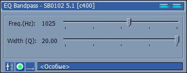
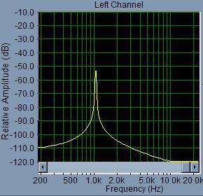
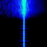
Filter result:

To increase the quality of the filter - you can make a chain of several objects. But if you need to change the frequency of the filter, you will need to change the parameters of each object. Also, since the signal being processed is usually mono, you can use both channels of the object. To do this, the signal is fed to the left input of the object, from the left output the processed signal is fed to the right input of the same object and the result is taken from the right output:

Filter result:
It is rather difficult to work with such a filter on the air, therefore it is necessary to provide for its disconnection for the time of the station search. To do this, you can apply one filter (as in the first variant) to search and another to work. To smoothly switch between them, you can use the crossfader:

Filter result:
8.2.SSB - filter
The simplest SSB filter is implemented using two objects: the low-pass filter and the high-pass filter (EQ Lopass and EQ Highpass)
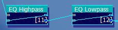
Select the upper, lower frequency and quality of the filter:
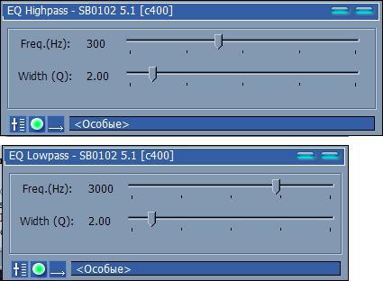
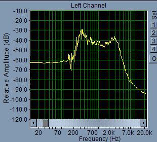
Filter result:
If the scheme is a bit more complicated and change the parameters:

, you can get the following result:

8.3.Notch - filter
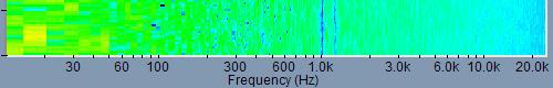
Notch - the filter ( used to cut frequencies from the signal ) is implemented using EQ Notch objects, connected in series:
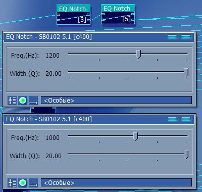
Each filter operates at a specific frequency and can be turned off with the “Bypass” button.
The difficulty is operational and accurate setting to the desired frequency: when controlling the fader with the mouse, the installation accuracy is much more than 1 Hz, and the control of the arrows on the keyboard is very slow.
8.4. Microphone signal processing
The DSP processor can be used not only to process the received signal, but also to adjust the broadcast. Since the KX drivers are focused on sound recording and sound processing, the choice is very large: equalizers, reverb, compression, etc.
8.4.1. Equalizer
The signal can be processed by the tone control or EQ. But the tone control allows you to adjust only the bass and treble. The graphic equalizer has 10 bands: 31 Hz, 62 Hz, 125 Hz, 250 Hz, 500 Hz, 1 KHz, 2 KHz, 4 KHz, 8 KHz, 16 KHz.

As you can see, not all bands can be used when operating SSB with a band up to 3 kHz. In this case, it is much more convenient to use a parametric equalizer, in which frequencies can be selected arbitrarily.

For example, RW3PS gives the following table with parameters [3] of a parametric equalizer for processing a signal from a microphone:
| Filtr | Mod | Freq | Fine | Bandwidth | Gain |
|---|---|---|---|---|---|
| one | PA | 63 | +5 | 70 | +14 |
| 2 | PA | 100 | 0 | 60 | -3 |
| 3 | PA | 125 | +3 | 60 | +3 |
| four | PA | 160 | -3 | 120 | -25 |
| five | PA | 200 | +3 | 60 | -3 |
| 6 | PA | 320 | +1 | 40 | +1 |
| 7 | PA | 400 | +6 | 60 | -15 |
| eight | PA | 800 | +1 | 40 | -one |
| 9 | PA | 1 K | +1 | five | -five |
| ten | PA | 1.6 K | -3 | five | -6 |
| eleven | PA | 2 K | +1 | 45 | -3 |
| 12 | PA | 3.2 K | 0 | five | +1 |
Let's try to do something similar. As you can see, 12 lanes are used. You can take either 2 by 5 lanes and 2 by one lane or 3 by 5 lanes:
Enter the values:

It remains only to figure out what Fine is and correctly select the Bandwidth ... :)
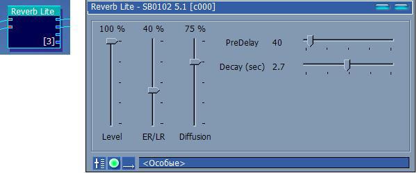
8.4.2. Reverb
Reverb objects will add volume to the signal. Parameters for taste.
Reverb Lite Object
More “tricked reverb” Reverb R from the additional set has the following form:

In addition to reverbs, you can experiment with Delay A and Delay B.
8.4.3.Other
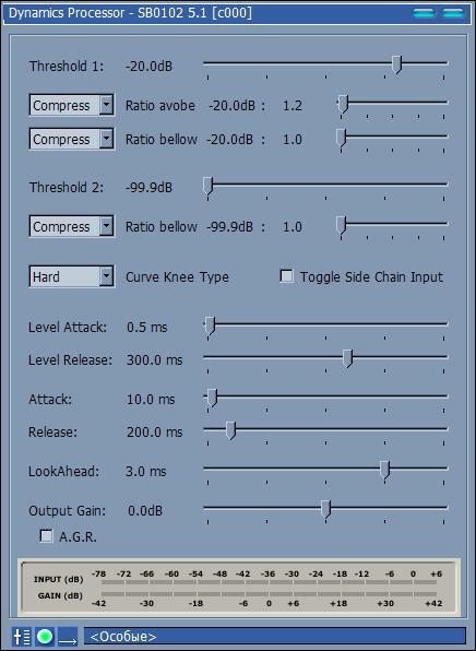
An interesting effect is obtained from the object Chorus (and Stereo Chorus). Using the APS Pitch object, you can raise or lower the voice by a certain number of semitones. Noise Gate will allow to realize the similarity of noise level. You can try to deal with a wide choice of compressors: Dynamics Processor, APS Compressor, APS Expander.
And many many others.
In general, in my opinion, the KX drivers do not have a software alternative for processing sound from a microphone ( over time, my opinion changed and I found AudioMulch and VST filters ). Some time ago I used a UA1FA transceiver with an MD-60 microphone. The quality of the signal, according to correspondents, was quite high. But it seemed strange to everyone that with a power of 100 watts I was so hard to hear. It has been suggested that there is insufficient microphone gain in the transceiver. And indeed - there is no gain control over the microphone in this version of the transceiver. To verify this statement, I connected the transceiver microphone to the input - a line-out from a computer (by experimentally selecting the level). A Dialog headset was used as a microphone. The following scheme was used for processing:

The GainHQ and Peak elements were used to ensure that after each filter the signal level was in the region of 0 dB. The Noise Gate 2T object was used for noise suppression in the room, High and Lowpass filters for bandwidth reduction, a ten-band equalizer for adjusting the frequency response and a compressor for the company. In the resulting signal there was no pronounced HF part (which is needed in the contests). The connection took place on 09.23.06 1841 with UA1WU. The operator was asked to compare the quality and level of the signal with the usual configuration. To my humble question, “are there any changes in the signal?” Vladimir answered, “FINAL !!! the level rose by 2 points, the signal was saturated and voluminous ". A further increase in the signal level led to overload and distortion in the signal (communication with UA3QPF, RX3QK, RK3QZ 24.09.06 1820-1823).
Continuation
The whole article in one post does not fit. To be continued…
The second part: Using the DSP sound card SB Live! for the benefit of radio amateurs (KX Driver's) - Part [2/2]
UPD.Thanks to CyberAP, my board moved from the shelf to the system unit:
Source: https://habr.com/ru/post/214755/
All Articles