Wattmeter absorbed microwave power and my participation in its development
Good day, dear readers. I registered on Habré for a long time, but did not dare to issue my first post.
I wanted to write something that might seem interesting. Time passed, and ideas never came.
And so, just the other day, I finished work on one of my first projects, after which, I had the idea to make a video review and write a small article about the device, on which I worked for a rather long period of time. I did not work alone, but it will be about the part that “hung” entirely on me.
')
First, it was necessary to develop a program that controls the charger. It consists largely of the ADUC814 microcontroller with a built-in analog-digital converter, five LEDs responsible for the battery charge level and the charge button. Everything is quite simple, I do not see the point of describing in detail. By interrupting the ADC, we get data that is then converted to volts, then using this value, the program makes certain decisions, such as what diodes to light, what to do at critical charge levels, etc., as well as watching the charge enable button.
Secondly, and this is actually the most difficult part for me, it was necessary to develop a program that controls the information processing and display unit. The components include the display, the keyboard, a pair of auxiliary LEDs and the AT89C51RC2 microcontroller (IC_BOI) controlling all of this. An overview of all the main functions of the power meter is presented in the video.
One of four transducers is connected to the wattmeter, depending on the measured power. The data from the converter is transferred to the analog-to-digital converter of the company Analog Devices and then transmitted via RS232 to another ADUC814 (MK_ATCP), in which they undergo preliminary processing. Program Prev processing and communication directly with the ADC was not developed by me.
MK_ATSP via RS232 receives from MK_BOI one of several commands, each of which consists of three bytes, then it analyzes the command and, depending on it, sends back three bytes of the command number and the requested result. This may be the number of the transducer or, for example, measurement results that are subjected to further mathematical processing. Some commands are responsible for zero correction or ADC calibration. There are about 8-9 teams in total, I don’t see the point either.
In the end, I would like to write a little about the functionality, which you can read more on video.
The main part of the keyboard buttons performs a dual function, auxiliary LEDs make it easier to navigate in the operating modes, of which there are only two, this is the menu mode, the upper diode is on and the operating mode is on, the lower diode is on.
All necessary information is displayed on the display. The value of the measured value, which also translates into dBm and dB, during the zero drift, negative values are also encountered, in these cases the message Err is displayed. The result of comparing the power with the value of Pc. The number of the connected inverter. Information that the STOP button is pressed, as well as when a specific transmitter is out of the possible measuring range, a corresponding message is also displayed.
I would also like to add that in addition to frequency correction coefficients, there is also a dynamic correction factor, calculated individually for each specific measurement.
That's all, I hope that there will be people who will enjoy this post, as well as I would like to see comments of a critical nature, maybe someone will have interesting ideas that I can implement in the future as part of this project, given what is planned replacing the MC_BOGI with a similar one, with a large memory capacity, since these 32 KB are packed to capacity.
Thanks for attention.
I apologize for the long break. In the comments there were questions about the process of programming itself, in this regard, I want to update this article and add code here.
Information output on the display was organized as follows. A list of duplicate phrases was compiled and the “alphabetLCD.h” library was written for them:
Since sometimes I had to display the results of the calculations implemented in “main.c”, I used the
The following are all the main "main.h" functions:
For the convenience of programming the display, calling its commands, moving the cursor in rows, etc. Macros were actively used:
TO BE CONTINUED...
I wanted to write something that might seem interesting. Time passed, and ideas never came.
And so, just the other day, I finished work on one of my first projects, after which, I had the idea to make a video review and write a small article about the device, on which I worked for a rather long period of time. I did not work alone, but it will be about the part that “hung” entirely on me.
')
For starters, I’ll give you some dry technical information.
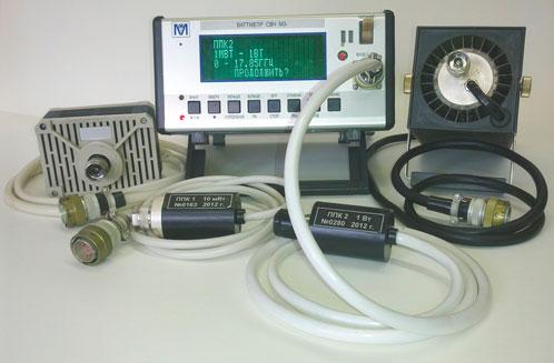
The wattmeter of the absorbed microwave power M3-114 is designed to measure in the coaxial path the average power of continuous and pulsed modulated microwave signals when powered from an industrial power network of 220 V, 50 Hz, and in standalone mode, from an internal or external battery 12 V. The device uses a four-line high-brightness vacuum-luminescent text display. Preparation of the device for operation is carried out in the dialogue mode, which simplifies operation. The device is equipped with an RS-232 port, which allows you to display data on a computer.
The operating frequency range is from 0.00 to 17.85 GHz.
The measurement range of average power from 1.0 µW to 100 watts.
In the range of the measured power of more than 10 mW at frequencies from 0 to 12.05 GHz, the limit of the basic error of the wattmeter does not exceed ± 4%, and in the frequency range from 12.05 GHz to 17.85 GHz - ± 6%.
KSVN wattmeter no more:
1.3 in the frequency range from 0.02 to 12.05 GHz;
1.4 in the frequency range above 12.05 to 17.85 GHz.
The instability of the wattmeter, taking into account the drift of the “electric zero” is not more than 40 μW / min.
The power consumed by the wattmeter from the mains voltage of 220 ± 22 V, frequency 50 ± 0.5 Hz when working with PPK1 - PPK3, not more than 12 VA, when working with PPK 4 - not more than 15 VA, when operating from an independent power source 6, 5 VA
Now let's go directly to the tasks that were set for me
First, it was necessary to develop a program that controls the charger. It consists largely of the ADUC814 microcontroller with a built-in analog-digital converter, five LEDs responsible for the battery charge level and the charge button. Everything is quite simple, I do not see the point of describing in detail. By interrupting the ADC, we get data that is then converted to volts, then using this value, the program makes certain decisions, such as what diodes to light, what to do at critical charge levels, etc., as well as watching the charge enable button.
Secondly, and this is actually the most difficult part for me, it was necessary to develop a program that controls the information processing and display unit. The components include the display, the keyboard, a pair of auxiliary LEDs and the AT89C51RC2 microcontroller (IC_BOI) controlling all of this. An overview of all the main functions of the power meter is presented in the video.
One of four transducers is connected to the wattmeter, depending on the measured power. The data from the converter is transferred to the analog-to-digital converter of the company Analog Devices and then transmitted via RS232 to another ADUC814 (MK_ATCP), in which they undergo preliminary processing. Program Prev processing and communication directly with the ADC was not developed by me.
MK_ATSP via RS232 receives from MK_BOI one of several commands, each of which consists of three bytes, then it analyzes the command and, depending on it, sends back three bytes of the command number and the requested result. This may be the number of the transducer or, for example, measurement results that are subjected to further mathematical processing. Some commands are responsible for zero correction or ADC calibration. There are about 8-9 teams in total, I don’t see the point either.
In the end, I would like to write a little about the functionality, which you can read more on video.
The main part of the keyboard buttons performs a dual function, auxiliary LEDs make it easier to navigate in the operating modes, of which there are only two, this is the menu mode, the upper diode is on and the operating mode is on, the lower diode is on.
A number of functions can be performed using the menu.
- Control display brightness
- Select the frequency range on which measurements are made. Depending on the selected range, certain correction factors are applied that affect the final result. The coefficients are calculated by comparing with the reference instrument.
- To establish a certain value P, with which the measured value is compared. The result is displayed in percent.
- Set the range of the measured value, when exiting from it, the corresponding message <Pmin,> Pmax is displayed
In the operation mode, the user can:
- Perform zero correction and ADC calibration.
- Enable averaging of the measured value or turn it off.
- “Freeze” the display by pressing the STOP button
All necessary information is displayed on the display. The value of the measured value, which also translates into dBm and dB, during the zero drift, negative values are also encountered, in these cases the message Err is displayed. The result of comparing the power with the value of Pc. The number of the connected inverter. Information that the STOP button is pressed, as well as when a specific transmitter is out of the possible measuring range, a corresponding message is also displayed.
I would also like to add that in addition to frequency correction coefficients, there is also a dynamic correction factor, calculated individually for each specific measurement.
That's all, I hope that there will be people who will enjoy this post, as well as I would like to see comments of a critical nature, maybe someone will have interesting ideas that I can implement in the future as part of this project, given what is planned replacing the MC_BOGI with a similar one, with a large memory capacity, since these 32 KB are packed to capacity.
Thanks for attention.
CODING
I apologize for the long break. In the comments there were questions about the process of programming itself, in this regard, I want to update this article and add code here.
Display alphabet
Information output on the display was organized as follows. A list of duplicate phrases was compiled and the “alphabetLCD.h” library was written for them:
void m3114(); // " -114" void noSignalADC(); // " " void wait(); // "" void norma(); // void PPK1(); void PPK2(); void PPK3(); void PPK4(); void prepareToWorkOnPPKEnter(); // "" void heating(); // 6 ? 34 void ifTNorm(); // =15-25 "" "" void Kcoeff(); // 1,000 void preparationOfMeasurement(); // 12 void resetMenuParams(); // void readyToMeasurement(); // void menuSet1(); // *** *** *** void switchOffSVCHAndPressEnter(); // " void preparationOfMeasurementCorrection0(); // "0" void preparationOfMeasurementCooling(); // 30 void preparationOfMeasurementStop32(); // 32 ? 24 void preparationToWork(); // void hertzType0(); // 0-1 1-4 4-8 8-12 void hertzType1(); // 12-15 15-17.85 void setPCompare(); // . ? 1,000 mW void setPCompareChange(); // . - : , void allowenceControlMin(); // min: ? , W void allowenceControlMax(); // max: ? , W void setAllowenceControlMin(); // min - : , void setAllowenceControlMax(); // max - : , void menuSet2(); // 4 8 16 void brightnessSet(); // 25% 50% 75% 100% void fault(); // !!! void incorrectValue(); // ! void overload(); // !!! > I will give an example of the implementation of one of the functions from “alphabetLCD.”
void noSignalADC() // " " { writeData('H'); writeData('E'); writeData('T'); writeData(' '); writeData('C'); writeData('B'); writeData(0x99); writeData(0x8D); writeData(0x8E); writeData(' '); writeData('C'); writeData(' '); writeData('A'); writeData(0x90); writeData(0x85); } Since sometimes I had to display the results of the calculations implemented in “main.c”, I used the
extern keyword: extern bit hertzType; extern float xdata calibrFl; extern unsigned char xdata ppkNumberCh; // char extern float xdata pCompareFl; extern float xdata pMinFl; // float extern float xdata pMaxFl; // float Let's move on to the main program.
The following are all the main "main.h" functions:
void initialization(); void delay(unsigned int); void delay2s(); void zeroCorrection(); void calibration(); void measurement(); //****UART**** void sendData (unsigned char); // send to UART //unsigned char recvData(); // recive from UART void iToA (int , char * ); void getPPKnumber(); //****Keyboard**** void keyboardInit(); void keyboardPolling(); void downZero(); void upCalibr(); void lessAveraging(); void morePC(); void commaStop(); void cancel(); void enter(); void menu(); //****Display**** void dispInit(); void writeCmd(int); void writeData(char); void readBF(); void returnHome(); void clearDisp(); void reloadDisp(); void moreLessCheck(); Macros
For the convenience of programming the display, calling its commands, moving the cursor in rows, etc. Macros were actively used:
/* __________MAKROS BLOCK__________ */ #define FIRST_LINE 0x80 #define SECOND_LINE 0xC0 #define THIRD_LINE 0x94 #define FOURTH_LINE 0xD4 #define CURSOR_HOME 0x02 #define CLEAR_DISP 0x01 #define DISP_OFF 0x08 #define DISP_ON_CB_OFF 0x0C // Disp ON cursore & blink OFF #define DISP_ON_CB_ON 0x0F #define FIRST_SIMBOL 0xD4 #define SECOND_SIMBOL 0xD5 #define THIRD_SIMBOL 0xD6 #define FOURTH_SIMBOL 0xD7 #define FIFTH_SIMBOL 0xD8 #define SIXTH_SIMBOL 0xD9 /* __________MAKROS BLOCK END__________ */ Configuring the processor legs
* __________PINS BLOCK__________ */ sbit E = P3^4; sbit RS = P3^6; sbit RW = P3^5; sbit workLed = P3^2; sbit menuLed = P3^3; sbit enterBut = P1^6; sbit cancelBut = P1^5; sbit uartPC = P3^7; /* __________PINS BLOCK END__________ */ Variable description
/* __________VARIABLES BLOCK__________ */ unsigned char keyPressed = 0; // key pressed value bit keyFlag = 0; // software flag unsigned char xdata uartDataRecv = 0; // unsigned char xdata uartDataSend = 0; // char xdata uartRecvCount = 0; // bit menuFlag = 0; // , 1 - , 0 - char xdata move = 1; // bit signalFlag = 0; // char xdata enterFlag = 0; // char xdata cancelFlag = 0; // bit modeFlag = 0; // bit brightnessFlag = 0; // , char xdata brightnessMove = 1; // char xdata brightnessSetFlag = 0; // , bit hertzFlag = 0; // , char xdata hertzSetFlag = 0; char xdata menuStep = 0; // char xdata hertzMove = 1; // bit hertzType; // bit compareFlag; // char xdata compareFlagEnter = 0; // char xdata compareFlagCancel = 0; // char xdata moreLess = 0x30; // char xdata moreLessFlag = 0; // bit moreFlag = 0; // 1 moreLess -= 2 bit lessFlag = 0; // 1 moreLess +=2 char xdata wattFlag = 0; // bit commaFlag = 0; // unsigned char xdata pCompare[10] = 0; // float xdata pCompareFl = 1.0; //float xdata pCompareFlTemp = 1.0; // . // , !!! bit controlFlag = 0; // char xdata controlFlagEnter = 0; // char xdata controlFlagCancel = 0; // unsigned char xdata pMin[10]; // min unsigned char xdata pMax[10]; // max float xdata pMinFl = 0; // float float xdata pMaxFl = 0; // float bit pMinFlag = 0; // min bit pMaxFlag = 0; // max unsigned char xdata zeroCoef1 = 50; // 50 - 200 unsigned char xdata zeroCoef2 = 30; // 50 - 200 unsigned char xdata zeroCoef3 = 30; // 50 - 200 unsigned char xdata zeroCoef4 = 100; // 50 - 200 unsigned long xdata zero; // unsigned char xdata calibrCoef1 = 50; // 50 - 200 unsigned char xdata calibrCoef2 = 30; // 50 - 200 unsigned char xdata calibrCoef3 = 30; // 50 - 200 unsigned char xdata calibrCoef4 = 100; // 50 - 200 unsigned long xdata calibr; // float xdata calibrFl; // unsigned int xdata PPK1CalibrPower; // 1 unsigned long xdata PPK23CalibrPower; // 1 - 2 unsigned long xdata PPK4CalibrPower; // 4 float xdata PPK1CalibrStandart; // (0,5 - 1,5) float xdata PPK2CalibrStandart; // (0,5 - 1,5) float xdata PPK3CalibrStandart; // (0,5 - 1,5) float xdata PPK4CalibrStandart; // (0,5 - 1,5) unsigned char xdata uartData[10]; // unsigned char xdata ppkNumberCh; // char float xdata measurementResult = 0; // bit averagingFlag = 0; // bit averaging4 = 0; // 4- bit averaging8 = 0; // 8- char xdata averagingMove = 1; // float idata hertzRate = 1; // 6() * 4() = 24 float idata dynamicRate = 1; // // 4() * 4() = 16 char idata stop = 0; // 1 , 0 char idata pc = 0; // //bit key = 0; xdata union { unsigned long bytes; unsigned char byteArr[4]; } byteUnion; /* __________VARIABLES BLOCK END__________ */ Interruptions
/* __________INTERUPTS BLOCK__________ */ void keyboard_interrupt() interrupt 7 using 1 { IEN1 &= ~(1<<0); // keyFlag = 0; keyPressed = KBF; /* save pressed key */ keyFlag = 1; /* set the software flag */ KBF = 0x00; /* clear keyboard flags */ delay(50000); // 50 mc IEN1 |= 0x01; // } void serial_IT(void) interrupt 4 { if (RI == 1) { uartDataRecv = SBUF; uartData[uartRecvCount] = uartDataRecv; ++uartRecvCount; } RI = 0; } /* __________INTERUPTS BLOCK END__________ */ TO BE CONTINUED...
Source: https://habr.com/ru/post/214291/
All Articles