Humidity Controller Atmega328
Recently I faced a trivial task - control of an exhaust fan at home in the bathroom.
It would seem that something easier, connect it to the light switch and ready. But, the operating time of the light is not constant and may not be enough to reduce the humidity, although this problem can be solved by setting the timer. In addition, my family does not like the working fan when taking water procedures, as it "creates a cold wind."
The second obvious solution was to simply put the fan on a separate switch and provide control to the person. But the human factor is such that the fan was constantly forgotten to turn on, and if turned on, turn off. Fan efficiency quickly went to zero.
')
I had to connect my passion for Arduino and simple microcontrollers to the case.
Shaking brains formulated
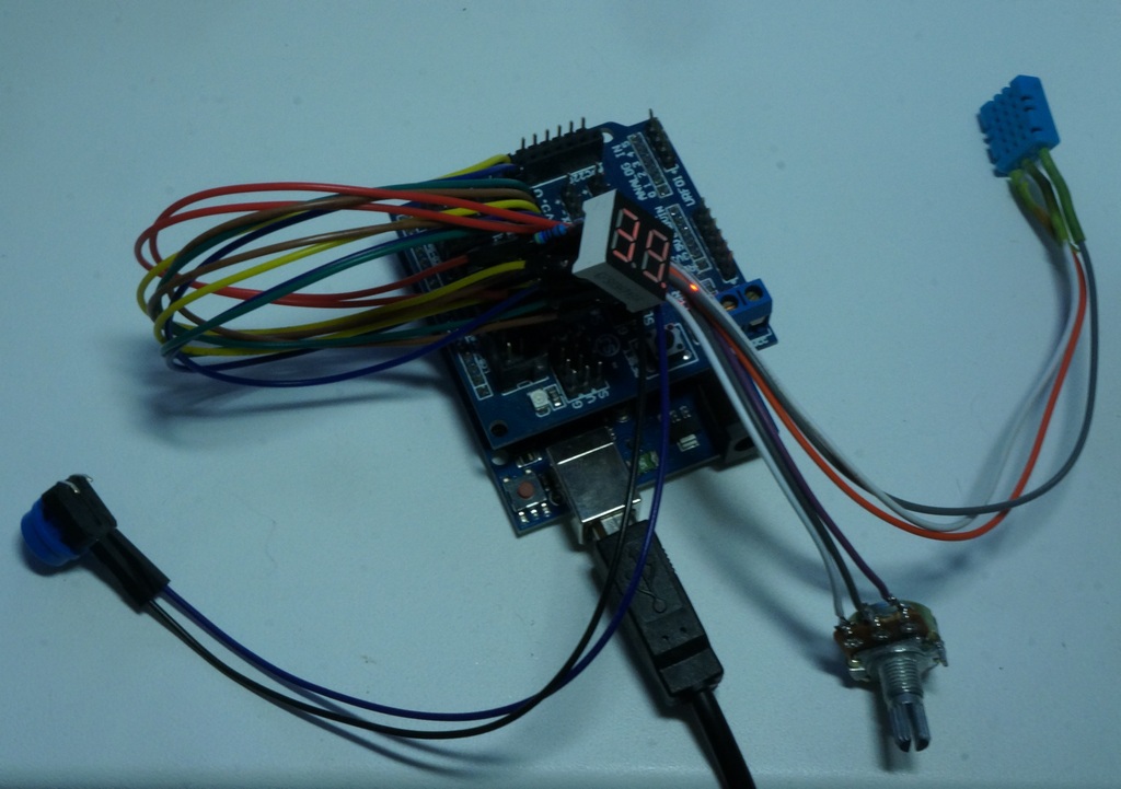
The prototype of this device was created on a Chinese-made Arduino Uno debug board:
Then everything was transferred to the Atmega328 microcontroller, stitched with a standard Arduin's bootloader.
The final device was created according to the principle "I blinded you from what was." All items were previously purchased on the Internet for various projects or torn out of non-working devices:
The LED driver 3x1W from the luminaire came up as the power source.
As the case was used a cross box from the old PBX.
Due to the fact thatthere was very laziness in the device, non-standard elements were used, the general scheme did not draw. I bring the table of connection of elements to the microcontroller:
The datasheet was not found on the CPS03621BR indicator, so the findings were found using a spear battery. The indicator appeared with a common anode. Cathode layout:
The fan is controlled by a simistor BT137.
Connection diagram taken from the site avr.ru
If someone thinks of repeating - CAUTION, there is 220V voltage on the case of the triac.
The microcontroller measures the humidity and temperature every 10 seconds.
Humidity cyclically accumulates in the archive of 6 values. If the current humidity is more than 3% above the first one from the archive or the absolute value of humidity is above 85%, then you need to turn on the fan.
The fan turns on for 20 minutes when there is no light on the photoresistor.
The button forcibly turns on the fan for 20 minutes (if it is not working) or turns it off (if it is working).
All constants in the algorithm were chosen experimentally.
The indicator cyclically displays the current temperature, humidity, and the inverse report timer.
The second discharge point lights up if a decrease in humidity is required and flashes if a command to turn on the fan is given.
The complete logic of the device can be described by a finite deterministic automaton.
The input alphabet of the automaton consists of the following events (in order of priority):
Many states:
Well, the state transition table of the automaton:
I did not install AVR-studio and other monsters, but I managed again with what was - IDE Arduino.
I create in the board.txt file a new controller working on an internal 8 MHz quartz:
I connect a cheap USBASP programmer to the ISCP connector of the Arduino UNO board and, inserting my Atmega328P into the socket, flashing the bootloader.
Now my microcontroller can be debugged and programmed via a standard bootloader on the UNO board, by selecting the appropriate board in the environment.
In this project, ready-made libraries for Arduino were used:
The first problem I encountered in the implementation was that the DHT11 sensor was not working. On Arduino UNO, everything is fine, but on a bare microcontroller does not work. The problem was in the frequency of the controller and timing of the DHT polling protocol.
In controllers operating at 8 MHz in the DHT library, it is necessary to specify the delay "3" (the third parameter in the class constructor) DHT dht (dhtPIN, DHT11, 3);
The second problem was the arbitrary operation of the reset and manual mode buttons. The reason for all was the interference from power wires passing close to these findings. First, the built-in pull-up resistor of the microcontroller on the corresponding pins was replaced with an external 10K. The interference has decreased, but has not disappeared altogether. The controller periodically lived its life independently turning on / off the fan.
Then I implemented software interference suppression - the button was interrogated in a row 10 times with a delay of 10 ms, and only with all 10 actuations, was the button pressed.
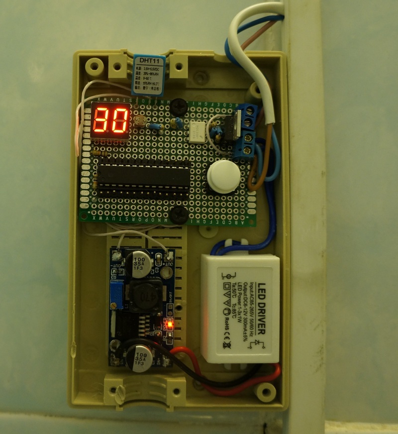
The finished device looks like this:
Now the fan control controller is in trial operation, and I am considering the control of the fan in the kitchen: from the switched on stove, smoke and the smell of gas.
List of useful links:
All articles my articles can be found in my blog samopal.pro
It would seem that something easier, connect it to the light switch and ready. But, the operating time of the light is not constant and may not be enough to reduce the humidity, although this problem can be solved by setting the timer. In addition, my family does not like the working fan when taking water procedures, as it "creates a cold wind."
The second obvious solution was to simply put the fan on a separate switch and provide control to the person. But the human factor is such that the fan was constantly forgotten to turn on, and if turned on, turn off. Fan efficiency quickly went to zero.
')
I had to connect my passion for Arduino and simple microcontrollers to the case.
Shaking brains formulated
Control device requirements
- the control device must operate in automatic mode;
- the fan should turn on from increased humidity;
- turning on the fan should not depend on the current level of humidity in the apartment;
- the fan should work when no one is in the bathroom;
- control device should be as simple and cheap as possible;
Element selection
The prototype of this device was created on a Chinese-made Arduino Uno debug board:
Then everything was transferred to the Atmega328 microcontroller, stitched with a standard Arduin's bootloader.
The final device was created according to the principle "I blinded you from what was." All items were previously purchased on the Internet for various projects or torn out of non-working devices:
- Atmega328P-PU microcontroller with socket ;
- breadboard ;
- DHT11 temperature and humidity sensor ;
- two-digit seven-segment indicator CPS03621BR from non-working hours;
- boxed photoresistor with amateur radio;
- voltage regulator on the LM2596 ;
- triac BT137 ;
- optoshimistor MOC3061 for galvanic isolation;
- button and several resistors
The LED driver 3x1W from the luminaire came up as the power source.
As the case was used a cross box from the old PBX.
Connection
Due to the fact that
- Pin 1 (Reset) through a 10K resistor to + (to avoid interference on this leg);
- Pin 2 (D0) - not used;
- Pin 3 (D1) - not used;
- Pin 4 (D2) - the cathode “G” of a seven-segment indicator;
- Pin 5 (D3) - cathode "." seven-segment indicator;
- Pin 6 (D4) - cathode “A” of a seven-segment indicator;
- Pin 7 (+) - 3.5V power supply;
- Pin 8 (-) - ground;
- Pin 9 (Clock) - not used;
- Pin 10 (Clock) - not used;
- Pin 11 (D5) - cathode “F” of a seven-segment indicator;
- Pin 12 (D6) - cathode “D” of a seven-segment indicator;
- Pin 13 (D7) - cathode “E” of a seven-segment indicator;
- Pin 14 (D8) - cathode "C" seven-segment indicator;
- Pin 15 (D9) - cathode “B” of a seven-segment indicator;
- Pin 16 (D10) - not used;
- Pin 17 (D11) - not used;
- Pin 18 (D12) - not used;
- Pin 19 (D13) - control of the fan on circuit;
- Pin 20 (+) - 3.5V power supply (double);
- Pin 21 (Aref) - not used;
- Pin 22 (-) - ground (double);
- Pin 23 (A0 / D14) - photoresistor with 27K pull-up resistor to ground;
- Pin 24 (A1 / D15) - input from the DHT11 sensor;
- Pin 25 (A2 / D16) - common anode of the 2nd digit of the seven-segment indicator through the 4.7K resistor;
- Pin 26 (A3 / D17) - common anode of the 1st digit of the seven-segment indicator through the 4.7K resistor;
- Pin 27 (A4 / D18) - button with pull-up resistor 10K +;
- Pin 28 (A5 / D19) - not used;
The datasheet was not found on the CPS03621BR indicator, so the findings were found using a spear battery. The indicator appeared with a common anode. Cathode layout:
The fan is controlled by a simistor BT137.
Connection diagram taken from the site avr.ru
If someone thinks of repeating - CAUTION, there is 220V voltage on the case of the triac.
Work algorithm
The microcontroller measures the humidity and temperature every 10 seconds.
Humidity cyclically accumulates in the archive of 6 values. If the current humidity is more than 3% above the first one from the archive or the absolute value of humidity is above 85%, then you need to turn on the fan.
The fan turns on for 20 minutes when there is no light on the photoresistor.
The button forcibly turns on the fan for 20 minutes (if it is not working) or turns it off (if it is working).
All constants in the algorithm were chosen experimentally.
The indicator cyclically displays the current temperature, humidity, and the inverse report timer.
The second discharge point lights up if a decrease in humidity is required and flashes if a command to turn on the fan is given.
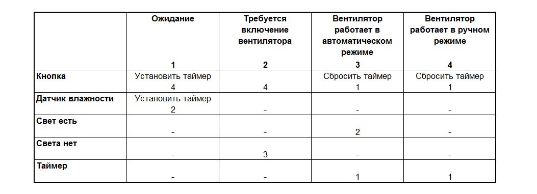
The complete logic of the device can be described by a finite deterministic automaton.
The input alphabet of the automaton consists of the following events (in order of priority):
- manual mode button pressed;
- humidity sensor tripped;
- the light is on;
- no light is on;
- The fan timer has been activated.
Many states:
- standby mode, the fan does not work, the time is off;
- the fan is turned on, the fan does not work, the timer (when) is stopped;
- the fan is in automatic mode, the timer is on;
- the fan is in manual mode, the timer is on;
Well, the state transition table of the automaton:
Programming
I did not install AVR-studio and other monsters, but I managed again with what was - IDE Arduino.
I create in the board.txt file a new controller working on an internal 8 MHz quartz:
atmega328_8.name=Atmega328 (5V, 8 MHz internal)

atmega328_8.upload.protocol=arduino
atmega328_8.upload.maximum_size=30720
atmega328_8.upload.speed=57600

atmega328_8.bootloader.low_fuses=0xE2
atmega328_8.bootloader.high_fuses=0xDE
atmega328_8.bootloader.extended_fuses=0x05
atmega328_8.bootloader.path=optiboot
atmega328_8.bootloader.file=optiboot_atmega328.hex
atmega328_8.bootloader.unlock_bits=0x3F
atmega328_8.bootloader.lock_bits=0x0F

atmega328_8.build.mcu=atmega328p
atmega328_8.build.f_cpu=8000000L
atmega328_8.build.core=arduino
atmega328_8.build.variant=standard
I connect a cheap USBASP programmer to the ISCP connector of the Arduino UNO board and, inserting my Atmega328P into the socket, flashing the bootloader.
Now my microcontroller can be debugged and programmed via a standard bootloader on the UNO board, by selecting the appropriate board in the environment.
In this project, ready-made libraries for Arduino were used:
- Arduino DHT library for working with a DHT11 sensor
- Seven Segment Display to work with the seven-segment indicator.
Full sketch code
#include <DHT.h> #include <SevenSegmentDisplay.h> #define DEBUG 1 #define TIMER_PERIOD 2400 #define ctrPIN 13 // #define dhtPIN 15 // #define btnPIN 18 // // void(* resetFunc) (void) = 0; // Reset MC function // SevenSegmentDisplay<true, BiDigit<17, 16> > ss(4, 9, 8, 6, 7, 5, 2, 3); // DHT11 8 DHT dht(dhtPIN, DHT11, 3);// 8 //DHT dht(dhtPIN, DHT11); //16 // FSM enum TMode { tmWait, // tmNeedPower, // tmAutoPower, // tmManualPower // }; // enum TDisplayMode { tdmTemp , // tdmHum , // tdmTimer // }; //int h_prev; int t,h,a0; int h_arr[6]; void setup() { // #ifdef DEBUG Serial.begin(9600); Serial.println("Humidity controller start ..."); #endif // pinMode(ctrPIN, OUTPUT); // digitalWrite(ctrPIN, LOW); // pinMode(btnPIN, INPUT); // digitalWrite(btnPIN, HIGH); // DHT11 dht.begin(); // h = dht.readHumidity(); for( int i=0; i<6; i++)h_arr[i] = h; } // 0.5 unsigned long cnt05 = 0; unsigned long ms1 = 0; // boolean flag_light = false; // boolean flag_btn = false; // boolean flag_hum = false; // unsigned int timer = 0; TMode mode = tmWait; TDisplayMode dmode = tdmTemp; boolean blink_stat = false; void loop () { unsigned long ms = millis(); int p = ms - ms1; // if( digitalRead(btnPIN) == LOW ){ int n = 1; for( int i=0; i<9; i++ ){ if( digitalRead(btnPIN) == LOW )n++; delay(10); } if( n > 9 )flag_btn = true; delay(400); #ifdef DEBUG Serial.println("Button is press"); #endif }//end if // , 0.5 if( p < 0 || p > 500 ){ cnt05++; ms1 = ms; // a0 = analogRead(A0); if( a0 > 1000 )flag_light = false; else flag_light = true; // 10 DHT11 if( cnt05%20 == 0 ){ h = dht.readHumidity(); t = dht.readTemperature(); // 3% 85% if( h - h_arr[5] > 3 || h > 85 )flag_hum = true; // for( int i=5; i>0; i--)h_arr[i] = h_arr[i-1]; h_arr[0] = h; #ifdef DEBUG Serial.print("VAL: Temp="); Serial.print(t); Serial.print(" H="); Serial.print(h); Serial.print(" A0="); Serial.print(a0); Serial.print(" X="); Serial.print(cnt05); Serial.print(" TM="); Serial.print(timer); Serial.print(" MODE="); Serial.print(mode); Serial.print(" DMODE="); Serial.print(dmode); Serial.println(""); #endif // switch( dmode ){ case tdmTemp : dmode = tdmHum; break; case tdmHum : dmode = tdmTimer; break; default: dmode = tdmTemp; }//end switch }//end if( cnt05%20 == 0 ) blink_stat = !blink_stat; SetStatusFSM(); }//end if( p < 0 || p > 500 ){ DisplayStatus(); }//end loop() /** * */ void DisplayStatus(){ // int point = -1; switch( mode ){ case tmNeedPower: point = 0; break; case tmAutoPower: case tmManualPower: if( blink_stat )point = 0; break; } switch( dmode ){ case tdmTemp : ss.print((unsigned)t,point,50); break; case tdmHum : ss.print((unsigned)h,point,50); break; case tdmTimer: // if( timer > 120 )ss.print((unsigned)(timer/120),point,50); // else if( timer > 0 )ss.print((unsigned)(timer/2),point,50); // 0 else ss.print(0,point,50); // ss.print((unsigned)(a0/100),point,50); break; }//end switch } /** * */ void SetStatusFSM(){ switch(mode){ // case tmWait : digitalWrite(ctrPIN, LOW); // if( flag_btn ){ timer = TIMER_PERIOD; mode = tmManualPower; } // else if( flag_hum ){ timer = TIMER_PERIOD; mode = tmNeedPower; } break; // case tmNeedPower: digitalWrite(ctrPIN, LOW); // if( flag_btn ){ mode = tmManualPower; } // else if( !flag_light ){ mode = tmAutoPower; } break; // " " case tmAutoPower: // digitalWrite(ctrPIN, HIGH); // if( timer > 0 )timer--; // if( flag_btn ){ mode = tmWait; timer = 0; } // else if( flag_light ){ mode = tmNeedPower; } // else if( timer <= 0 ){ timer = 0; mode = tmWait; } break; // " " case tmManualPower: // digitalWrite(ctrPIN, HIGH); // if( timer > 0 )timer--; // if( flag_btn ){ mode = tmWait; timer = 0; } // else if( timer <= 0 ){ timer = 0; mode = tmWait; } break; } // flag_btn = false; flag_hum = false; } Problems
The first problem I encountered in the implementation was that the DHT11 sensor was not working. On Arduino UNO, everything is fine, but on a bare microcontroller does not work. The problem was in the frequency of the controller and timing of the DHT polling protocol.
In controllers operating at 8 MHz in the DHT library, it is necessary to specify the delay "3" (the third parameter in the class constructor) DHT dht (dhtPIN, DHT11, 3);
The second problem was the arbitrary operation of the reset and manual mode buttons. The reason for all was the interference from power wires passing close to these findings. First, the built-in pull-up resistor of the microcontroller on the corresponding pins was replaced with an external 10K. The interference has decreased, but has not disappeared altogether. The controller periodically lived its life independently turning on / off the fan.
Then I implemented software interference suppression - the button was interrogated in a row 10 times with a delay of 10 ms, and only with all 10 actuations, was the button pressed.
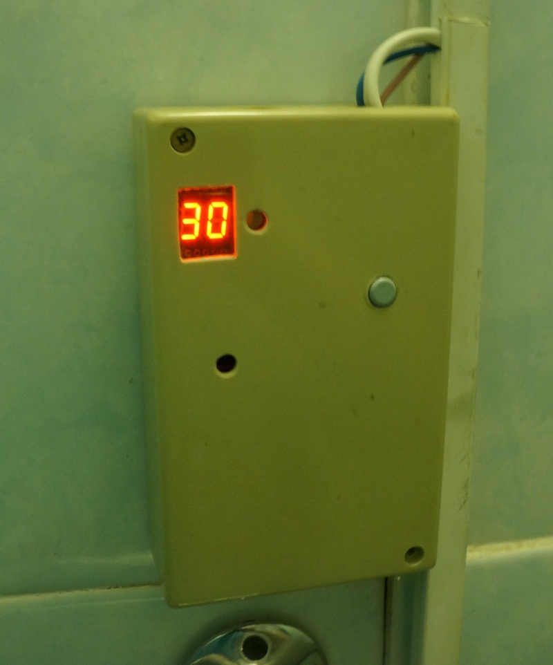
The finished device looks like this:
Now the fan control controller is in trial operation, and I am considering the control of the fan in the kitchen: from the switched on stove, smoke and the smell of gas.
List of useful links:
- Technical description of the Atmega328P microcontroller
- Power control from the microcontroller
- Fill the bootloader in the microcontroller
- Duino on the internal resonator
- FUSE configuration bit
All articles my articles can be found in my blog samopal.pro
Source: https://habr.com/ru/post/213789/
All Articles