Writing a driver for an LCD display under embedded linux
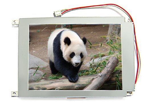
In this article I want to share my experience of writing linux drivers for the 320x240 color display from the manufacturer Newhavendisplays, namely NHD-5.7-320240WFB-CTXI-T1 under embedded linux. The idea to write an article has ripened precisely because of the fact that there are not so many resources on writing framebufer (FB) drivers, especially in Russian. The module was written far from under the newest kernel (2.6.30), so I admit that in FB interfaces a lot of things have changed since then. But, nevertheless, I hope the article will be of interest to those interested in developing the linux kernel level. I do not exclude that the implementation could be made simpler and more elegant, therefore comments and comments are welcome.
')
Prehistory
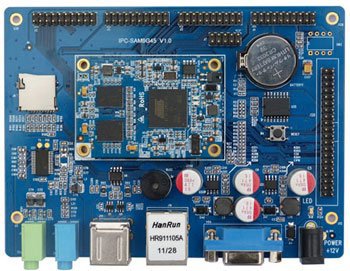
Initially, the task was to write a driver, which could be accessed using standard tools such as QT embedded, to ultimately build a simple menu with icons and text for user interaction. The platform was a scarf on the AT91SAM9G45, or rather, www.armdevs.com/IPC-SAM9G45.html
Streaming video was not planned. The AT91SAM9G45 contains a fully functional built-in LCD controller with DMA support and a fairly high-speed bus, which could potentially have a decent speed for video, but alas, hardwired, it is not compatible with SSD1963. Therefore, it was decided to use an ordinary GPIO interface for this purpose, as the only available alternative.
Controller Interface SSD1963
The controller interface is easiest to present in the form of a picture from the datasheet of the display:
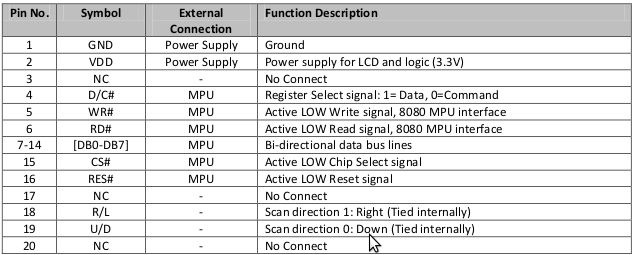
From the point of view of the driver developer, we are interested in the DB0 - DB7 pins. This is an 8-bit data bus, and DC, RD, WR, CS, RES pins are used to control the data transfer process on the SSD1963.
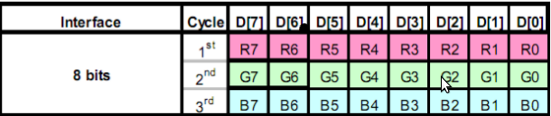
As for the format of the transmitted data, this display uses the 888 format. What it means: 8 bytes - Red, 8 bytes - Green, 8 bytes - Blue. Still quite often in the displays of this type can be found options 555, 565, etc., but this is not our case. The format of the transmitted data is shown in the figure.
Before the first data byte is put on the bus, the CS and WR pins must switch from 1 to 0. And after the data byte is set, CS and WR switches from 0 to 1, which actually transfers the byte data to the controller SSD1963. More detailed waveforms of signals can be viewed in the datasheet on the controller. www.newhavendisplay.com/app_notes/SSD1963.pdf
In the source code, the interface will be described with arrays of GPIO pins:
The transfer function of bytes on this interface is:
As you can see, using this function, you can send commands (for example, to configure the display) and data in the form of pixels to the LCD controller.
Framebuffer core model
As you know, the linux kernel provides interfaces for different types of device drivers — char drivers, block drivers, usb drivers, etc. The Framebuffer driver is also a separate subsystem in the Linux driver model. The main structure that is used to represent the FB driver is the struct fb_info in linux / fb.h. By the way, this header file will also be interesting to fans of humor in the linux code of the kernel, since it contains an interesting define -
#define STUPID_ACCELF_TEXT_SHIT . I think the name speaks for itself. But, back to the fb_info structure. We will be interested in two structures that it contains - fb_var_screeninfo and fb_fix_screeninfo . We initialize them with the parameters of our display.
In our case, 4 bytes will be allocated per pixel: 8-Red, 8-Green, 8-Blue, 8-Transparent
Let me explain some of the fields of the structures:
.type is a way to allocate bits that describe pixels in memory. Packed pixels means that the bytes (in our case, 8888 will be placed one after the other).
.visual - display color depth. In our case, this is truecolor - 24bit color depth
.accel - hardware acceleration
.transp, red, green, blue - just set our 8,8,8,8 format in the form of three fields - offset, length and msb_right .
Also, in order to register our driver in the kernel, it is necessary to describe two more entities - the device (device) and the driver (driver). We describe the FB device ( struct ssd1963 ), which will contain the pages of our video memory ( struct ss1963_page ):
Initialization
As with any other Linux kernel module, we describe a couple of init / remove functions. Let's start with init. Framebuffer drivers are usually registered in the system as platform_driver :
In turn, the Platform driver calls the probe function for a specific driver, which performs all the necessary operations — allocating memory, reserving resources, initializing structures, etc. Here is an example of the ssd1963_probe function:
A few comments on the function. Here we are consistently:
- Allocate memory for our device ssd1963
- We allocate memory and initialize the fb_info structure , first with default values ( framebuffer_alloc ), since we don’t need to change many parameters, and then with specific values for our driver, like fb_var_screeninfo, fb_fix_screeninfo and fb_ops , which we will consider a little later.
- Allocates memory for a continuous buffer of pixels in virtual memory, which will be used to record user-space processes.
- Select the ssd1963_page for each page in the virtual memory of the framebuffer. Each ssd1963_page will contain the address of the beginning of the page buffer relative to the common FB buffer, the shift in x, the shift in y, and the length of the page buffer. In our case, the framebuffer capacity = line_length * height = 320 * 4 * 240 = 307200 bytes. For this buffer capacity, we need line_length * height / PAGE_SIZE = 307200/4096 = 75 pages. Note how they will be located in the memory FB. Understanding this page layout will come in handy when we look at the ssd1963_copy function a little later:

- We register our FB in the system ( register_framebuffer ) and initialize the pending data update procedure ( fb_deferred_io_init ), more about this in the section “ Framebuffer Operations”.
- ssd1963_setup configures the required GPIOs on the AT91SAM9G45 CPU and performs the initial setup of the LCD controller. The initial configuration algorithm in the form of sending a set of mysterious bytes in hex is taken from the documentation on SSD1963, therefore I will only give here a part of the function:
- ssd1963_update_all sets the must_update = 1 flag for all pages and initiates the mechanism for updating the display in the deferred context by calling schedule_delayed_work (& item-> info-> deferred_work, fbdefio-> delay);
So, you have dealt with init, with the remove function, everything is much simpler, freeing the allocated memory, and returning the FB structure to the kernel:
Framebuffer operations
So, it's time to consider the fb_ops structure:
I don’t include all the structure methods here, the curious reader will be able to find them in the source code of the module or in any other driver in the kernel code in the drivers / video directory. As you may have guessed, the fb_ops structure describes the actions that our driver can perform. Fortunately, the kernel developers have partially facilitated our work by providing standard functions for working with FB with sys_ or fb_sys suffix , for example fb_sys_read . We only need to add functionality to our implementation of functions from fb_ops ( ssd1963_read, ssd1963_write , etc.) that allows us to update the data in our improvised video memory when the need arises.
For example, the ssd1963_fillrect function would look like this:
Obviously, the fb_fillrect system call will update the video data in a specific rectangular area of the screen, so we need to specify which pages we need to refresh by marking them with the must_update flag, and then manually triggering the video memory update procedure:
Updating data in video memory occurs in the form of a deferred context. User-space application working with graphics, will not wait for the completion of the recording of each frame in the video memory, which is quite logical. Deferred processing in fb_info is defined as a fb_deferred_io structure:
Ssd1963_update function with prototype
void ssd1963_update (struct fb_info * info, struct list_head * pagelist);
does not update all pages, but only pages that were modified as a result of user-space being rewritten by the process, or as a result of a system call, such as fb_fillrect and company. Accordingly, the function has the form:
At this stage, you probably wondered what the ssd1963_copy function does . It does all the “dirty” work of transferring data from video memory pages to an artificially created, 8-bit GPIO-based bus.
Ssd1963_copy function
Here it is necessary to recall the figure, which depicts how our pages in memory correspond to the pixels of the display. We see, for example, that page [0] stores information for the top three lines of the display, 320 pixels each, and 64 pixels for the 4th line. We have 75 such pages, and the picture from the picture, and as it is not difficult to notice, page [5] will look the same - 3 lines of 320 and one each of 64. Accordingly, the function that takes the page index as a parameter will contain a switch (index% 5) and, depending on the offset for each specific page, send data to the “window” allocated to it in the display memory. The function is quite long, so I will give only its part
Here the nhd_set_window function configures using the already known nhd_write_data (NHD_COMMAND, ...); display area in which data will be written (pixels).
nhd_write_data (NHD_COMMAND, 0x2c); - the command to the LCD controller that the data flow will now follow.
And finally, a screenshot of the ts_calibrate program from the tslib package on the device with the display.
Who is interested - I can send the full code of the module:

')
Prehistory
Initially, the task was to write a driver, which could be accessed using standard tools such as QT embedded, to ultimately build a simple menu with icons and text for user interaction. The platform was a scarf on the AT91SAM9G45, or rather, www.armdevs.com/IPC-SAM9G45.html
Streaming video was not planned. The AT91SAM9G45 contains a fully functional built-in LCD controller with DMA support and a fairly high-speed bus, which could potentially have a decent speed for video, but alas, hardwired, it is not compatible with SSD1963. Therefore, it was decided to use an ordinary GPIO interface for this purpose, as the only available alternative.
Controller Interface SSD1963
The controller interface is easiest to present in the form of a picture from the datasheet of the display:
From the point of view of the driver developer, we are interested in the DB0 - DB7 pins. This is an 8-bit data bus, and DC, RD, WR, CS, RES pins are used to control the data transfer process on the SSD1963.
As for the format of the transmitted data, this display uses the 888 format. What it means: 8 bytes - Red, 8 bytes - Green, 8 bytes - Blue. Still quite often in the displays of this type can be found options 555, 565, etc., but this is not our case. The format of the transmitted data is shown in the figure.
Before the first data byte is put on the bus, the CS and WR pins must switch from 1 to 0. And after the data byte is set, CS and WR switches from 0 to 1, which actually transfers the byte data to the controller SSD1963. More detailed waveforms of signals can be viewed in the datasheet on the controller. www.newhavendisplay.com/app_notes/SSD1963.pdf
In the source code, the interface will be described with arrays of GPIO pins:
static unsigned int nhd_data_pin_config[] = { AT91_PIN_PE13, AT91_PIN_PE14, AT91_PIN_PE17, AT91_PIN_PE18, AT91_PIN_PE19, AT91_PIN_PE20, AT91_PIN_PE21, AT91_PIN_PE22 }; static unsigned int nhd_gpio_pin_config[] = { AT91_PIN_PE0, // RESET AT91_PIN_PE2, // DC AT91_PIN_PE5, // CLK AT91_PIN_PE6, // RD AT91_PIN_PE1 // WR }; The transfer function of bytes on this interface is:
static void nhd_write_data(int command, unsigned short value) { int i; at91_set_gpio_output(AT91_PIN_PE12, 1); //R/D for (i=0; i<ARRAY_SIZE(nhd_data_pin_config); i++) at91_set_gpio_output(nhd_data_pin_config[i], (value>>i)&0x01); if (command) at91_set_gpio_output(AT91_PIN_PE10, 0); //D/C else at91_set_gpio_output(AT91_PIN_PE10, 1); //D/C at91_set_gpio_output(AT91_PIN_PE11, 0); //WR at91_set_gpio_output(AT91_PIN_PE26, 0); //CS at91_set_gpio_output(AT91_PIN_PE26, 1); //CS at91_set_gpio_output(AT91_PIN_PE11, 1); //WR } As you can see, using this function, you can send commands (for example, to configure the display) and data in the form of pixels to the LCD controller.
Framebuffer core model
As you know, the linux kernel provides interfaces for different types of device drivers — char drivers, block drivers, usb drivers, etc. The Framebuffer driver is also a separate subsystem in the Linux driver model. The main structure that is used to represent the FB driver is the struct fb_info in linux / fb.h. By the way, this header file will also be interesting to fans of humor in the linux code of the kernel, since it contains an interesting define -
#define STUPID_ACCELF_TEXT_SHIT . I think the name speaks for itself. But, back to the fb_info structure. We will be interested in two structures that it contains - fb_var_screeninfo and fb_fix_screeninfo . We initialize them with the parameters of our display.
static struct fb_fix_screeninfo ssd1963_fix __initdata = { .id = "SSD1963", .type = FB_TYPE_PACKED_PIXELS, .visual = FB_VISUAL_TRUECOLOR, .accel = FB_ACCEL_NONE, .line_length = 320 * 4, }; static struct fb_var_screeninfo ssd1963_var __initdata = { .xres = 320, .yres = 240, .xres_virtual = 320, .yres_virtual = 240, .width = 320, .height = 240, .bits_per_pixel = 32, .transp = {24, 8, 0}, .red = {16, 8, 0}, .green = {8, 8, 0}, .blue = {0, 8, 0}, .activate = FB_ACTIVATE_NOW, .vmode = FB_VMODE_NONINTERLACED, }; In our case, 4 bytes will be allocated per pixel: 8-Red, 8-Green, 8-Blue, 8-Transparent
Let me explain some of the fields of the structures:
.type is a way to allocate bits that describe pixels in memory. Packed pixels means that the bytes (in our case, 8888 will be placed one after the other).
.visual - display color depth. In our case, this is truecolor - 24bit color depth
.accel - hardware acceleration
.transp, red, green, blue - just set our 8,8,8,8 format in the form of three fields - offset, length and msb_right .
Also, in order to register our driver in the kernel, it is necessary to describe two more entities - the device (device) and the driver (driver). We describe the FB device ( struct ssd1963 ), which will contain the pages of our video memory ( struct ss1963_page ):
struct ssd1963_page { unsigned short x; unsigned short y; unsigned long *buffer; unsigned short len; int must_update; }; struct ssd1963 { struct device *dev; struct fb_info *info; unsigned int pages_count; struct ssd1963_page *pages; }; struct platform_driver ssd1963_driver = { .probe = ssd1963_probe, .remove = ssd1963_remove, .driver = { .name = "ssd1963" } }; Initialization
As with any other Linux kernel module, we describe a couple of init / remove functions. Let's start with init. Framebuffer drivers are usually registered in the system as platform_driver :
static int __init ssd1963_init(void) { int ret = 0; ret = platform_driver_register(&ssd1963_driver); if (ret) { pr_err("%s: unable to platform_driver_register\n", __func__); } return ret; } module_init(ssd1963_init); In turn, the Platform driver calls the probe function for a specific driver, which performs all the necessary operations — allocating memory, reserving resources, initializing structures, etc. Here is an example of the ssd1963_probe function:
static int __init ssd1963_probe(struct platform_device *dev) { int ret = 0; struct ssd1963 *item; struct fb_info *info; // Allocating memory for ssd1663 device item = kzalloc(sizeof(struct ssd1963), GFP_KERNEL); if (!item) { dev_err(&dev->dev, "%s: unable to kzalloc for ssd1963\n", __func__); ret = -ENOMEM; goto out; } item->dev = &dev->dev; dev_set_drvdata(&dev->dev, item); // Initializing fb_info struct using kernel framebuffer API info = framebuffer_alloc(sizeof(struct ssd1963), &dev->dev); if (!info) { ret = -ENOMEM; dev_err(&dev->dev, "%s: unable to framebuffer_alloc\n", __func__); goto out_item; } item->info = info; //Here info->par pointer is commonly used to store private data // In our case, we can use it to store pointer to ssd1963 device info->par = item; info->dev = &dev->dev; info->fbops = &ssd1963_fbops; info->flags = FBINFO_FLAG_DEFAULT; info->fix = ssd1963_fix; info->var = ssd1963_var; ret = ssd1963_video_alloc(item); if (ret) { dev_err(&dev->dev, "%s: unable to ssd1963_video_alloc\n", __func__); goto out_info; } info->screen_base = (char __iomem *)item->info->fix.smem_start; ret = ssd1963_pages_alloc(item); if (ret < 0) { dev_err(&dev->dev, "%s: unable to ssd1963_pages_init\n", __func__); goto out_video; } info->fbdefio = &ssd1963_defio; fb_deferred_io_init(info); ret = register_framebuffer(info); if (ret < 0) { dev_err(&dev->dev, "%s: unable to register_frambuffer\n", __func__); goto out_pages; } ssd1963_setup(item); ssd1963_update_all(item); return ret; out_pages: ssd1963_pages_free(item); out_video: ssd1963_video_free(item); out_info: framebuffer_release(info); out_item: kfree(item); out: return ret; } A few comments on the function. Here we are consistently:
- Allocate memory for our device ssd1963
- We allocate memory and initialize the fb_info structure , first with default values ( framebuffer_alloc ), since we don’t need to change many parameters, and then with specific values for our driver, like fb_var_screeninfo, fb_fix_screeninfo and fb_ops , which we will consider a little later.
- Allocates memory for a continuous buffer of pixels in virtual memory, which will be used to record user-space processes.
- Select the ssd1963_page for each page in the virtual memory of the framebuffer. Each ssd1963_page will contain the address of the beginning of the page buffer relative to the common FB buffer, the shift in x, the shift in y, and the length of the page buffer. In our case, the framebuffer capacity = line_length * height = 320 * 4 * 240 = 307200 bytes. For this buffer capacity, we need line_length * height / PAGE_SIZE = 307200/4096 = 75 pages. Note how they will be located in the memory FB. Understanding this page layout will come in handy when we look at the ssd1963_copy function a little later:
- We register our FB in the system ( register_framebuffer ) and initialize the pending data update procedure ( fb_deferred_io_init ), more about this in the section “ Framebuffer Operations”.
- ssd1963_setup configures the required GPIOs on the AT91SAM9G45 CPU and performs the initial setup of the LCD controller. The initial configuration algorithm in the form of sending a set of mysterious bytes in hex is taken from the documentation on SSD1963, therefore I will only give here a part of the function:
void ssd1963_setup(struct ssd1963 *item) { nhd_init_gpio_regs(); //initializations of pins in nhd_data-gpio_pin_config at91_set_gpio_output(AT91_PIN_PE27, 0); //RESET udelay(5); at91_set_gpio_output(AT91_PIN_PE27, 1); //RESET udelay(100); nhd_write_data(NHD_COMMAND, 0x01); //Software Reset ... nhd_write_to_register(0xe0, 0x03); //LOCK PLL nhd_write_data(NHD_COMMAND, 0xb0); //SET LCD MODE TFT 18Bits nhd_write_data(NHD_DATA, 0x0c); //SET MODE 24 bits & hsync+Vsync+DEN … } - ssd1963_update_all sets the must_update = 1 flag for all pages and initiates the mechanism for updating the display in the deferred context by calling schedule_delayed_work (& item-> info-> deferred_work, fbdefio-> delay);
So, you have dealt with init, with the remove function, everything is much simpler, freeing the allocated memory, and returning the FB structure to the kernel:
static int ssd1963_remove(struct platform_device *device) { struct fb_info *info = platform_get_drvdata(device); struct ssd1963 *item = (struct ssd1963 *)info->par; if (info) { unregister_framebuffer(info); ssd1963_pages_free(item); ssd1963_video_free(item); framebuffer_release(info); kfree(item); } return 0; } Framebuffer operations
So, it's time to consider the fb_ops structure:
static struct fb_ops ssd1963_fbops = { .owner = THIS_MODULE, .fb_read = fb_sys_read, .fb_write = ssd1963_write, .fb_fillrect = ssd1963_fillrect, .fb_copyarea = ssd1963_copyarea, .fb_imageblit = ssd1963_imageblit, .fb_setcolreg = ssd1963_setcolreg, .fb_blank = ssd1963_blank, }; I don’t include all the structure methods here, the curious reader will be able to find them in the source code of the module or in any other driver in the kernel code in the drivers / video directory. As you may have guessed, the fb_ops structure describes the actions that our driver can perform. Fortunately, the kernel developers have partially facilitated our work by providing standard functions for working with FB with sys_ or fb_sys suffix , for example fb_sys_read . We only need to add functionality to our implementation of functions from fb_ops ( ssd1963_read, ssd1963_write , etc.) that allows us to update the data in our improvised video memory when the need arises.
For example, the ssd1963_fillrect function would look like this:
static void ssd1963_fillrect(struct fb_info *p, const struct fb_fillrect *rect) { sys_fillrect(p, rect); ssd1963_touch(p, rect->dx, rect->dy, rect->width, rect->height); } Obviously, the fb_fillrect system call will update the video data in a specific rectangular area of the screen, so we need to specify which pages we need to refresh by marking them with the must_update flag, and then manually triggering the video memory update procedure:
static void ssd1963_touch(struct fb_info *info, int x, int y, int w, int h) { struct fb_deferred_io *fbdefio = info->fbdefio; struct ssd1963 *item = (struct ssd1963 *)info->par; int i, ystart, yend; if (fbdefio) { //Touch the pages, so the deferred io will update them. for (i=0; i<item->pages_count; i++) { ystart=item->pages[i].y; yend=item->pages[i].y+(item->pages[i].len/info->fix.line_length)+1; if (!((y+h)<ystart || y>yend)) { item->pages[i].must_update=1; } } //Schedule the deferred IO to kick in after a delay. schedule_delayed_work(&info->deferred_work, fbdefio->delay); } } Updating data in video memory occurs in the form of a deferred context. User-space application working with graphics, will not wait for the completion of the recording of each frame in the video memory, which is quite logical. Deferred processing in fb_info is defined as a fb_deferred_io structure:
static struct fb_deferred_io ssd1963_defio = { .delay = HZ / 20, .deferred_io = &ssd1963_update, }; Ssd1963_update function with prototype
void ssd1963_update (struct fb_info * info, struct list_head * pagelist);
does not update all pages, but only pages that were modified as a result of user-space being rewritten by the process, or as a result of a system call, such as fb_fillrect and company. Accordingly, the function has the form:
static void ssd1963_update(struct fb_info *info, struct list_head *pagelist) { struct ssd1963 *item = (struct ssd1963 *)info->par; struct page *page; int i; list_for_each_entry(page, pagelist, lru) { item->pages[page->index].must_update=1; } //Copy changed pages. for (i=0; i<item->pages_count; i++) { if (item->pages[i].must_update) { item->pages[i].must_update=0; ssd1963_copy(item, i); } } } At this stage, you probably wondered what the ssd1963_copy function does . It does all the “dirty” work of transferring data from video memory pages to an artificially created, 8-bit GPIO-based bus.
Ssd1963_copy function
Here it is necessary to recall the figure, which depicts how our pages in memory correspond to the pixels of the display. We see, for example, that page [0] stores information for the top three lines of the display, 320 pixels each, and 64 pixels for the 4th line. We have 75 such pages, and the picture from the picture, and as it is not difficult to notice, page [5] will look the same - 3 lines of 320 and one each of 64. Accordingly, the function that takes the page index as a parameter will contain a switch (index% 5) and, depending on the offset for each specific page, send data to the “window” allocated to it in the display memory. The function is quite long, so I will give only its part
static void ssd1963_copy(struct ssd1963 *item, unsigned int index) { unsigned short x,y, startx, endx, starty, endy, offset; unsigned long *buffer; unsigned int len; unsigned int count; x = item->pages[index].x; y = item->pages[index].y; buffer = item->pages[index].buffer; len = item->pages[index].len; switch (index%5) { case 0: offset = 0; startx = x; starty = y; endx = 319; endy = y+2; len = 960; nhd_set_window(startx, endx, starty, endy); nhd_write_data(NHD_COMMAND, 0x2c); for (count = 0; count < len; count++) { nhd_write_data(NHD_DATA,(unsigned char)((buffer[count+offset])>>16)); //red nhd_write_data(NHD_DATA,(unsigned char)((buffer[count+offset])>>8)); //green nhd_write_data(NHD_DATA,(unsigned char)(buffer[count+offset])); //blue } offset = len; startx = x; starty = y+3; endx = x+63; endy = y+3; len = 64; nhd_set_window(startx, endx, starty, endy); nhd_write_data(NHD_COMMAND, 0x2c); for (count = 0; count < len; count++) { nhd_write_data(NHD_DATA,(unsigned char)((buffer[count+offset])>>16)); //red nhd_write_data(NHD_DATA,(unsigned char)((buffer[count+offset])>>8)); //green nhd_write_data(NHD_DATA,(unsigned char)(buffer[count+offset])); //blue } break; case 1: …. Here the nhd_set_window function configures using the already known nhd_write_data (NHD_COMMAND, ...); display area in which data will be written (pixels).
nhd_write_data (NHD_COMMAND, 0x2c); - the command to the LCD controller that the data flow will now follow.
And finally, a screenshot of the ts_calibrate program from the tslib package on the device with the display.
Who is interested - I can send the full code of the module:
Source: https://habr.com/ru/post/213775/
All Articles