Powerful laboratory power supply
Not so long ago bought a soldering station. It has long been engaged in amateur electronics, and then came the moment when he realized that it was time. Prior to that, he used a batin self-made unit that combined a laboratory power supply and a low-voltage soldering iron power supply. And now the problem arose before me: I put the soldering station, and keep the old unit for the sake of the frail and inaccurate 0-30v 3A power supply unit or did I buy something modern, with current protection and digital indicators? Crawling on ebay, I realized that the maximum that shines for me is for 7-10 thousand to buy a Chinese unit with a current maximum of 5A. Toad said her weighty "kva", her arms itched and ...
Now to the point. Formed the requirements for the unit: at least 0-30V, with currents of at least 10A, with adjustable current protection, and with the accuracy of adjustment for voltage 0.1V. And what would become even more interesting - 2 channels, even from the common ground. The voltage setting must be digital, i.e. no variable resistors, only encoders. Fixed voltage settings and memorization are optional.
To indicate the output status, Chinese digital combination indicators were selected on the LCD, with a range of up to 199V with an accuracy of 0.1V and up to 20A with an accuracy of 0.01A. What suits me completely. But what I forgot is to buy shunts for them, because naively thought that they would be included.
For the primary voltage conversion, I thought of using a conventional transformer with taps every 6V, switched by relays from the controller, and a simple emitter follower to adjust the output. And everything would be fine, but when I learned the cost and dimensions of such a transformer (30V * 10A = 300W), I realized that I need to be more modern and use pulsed power supplies.
')
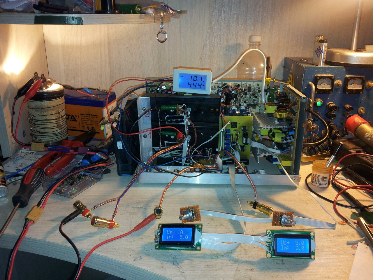
Having run through the sentences I realized that there is nothing sensible about my currents, and if there is, then the toad is categorically against. In this regard, the thought came to try to use computer power supply units, of which there is always plenty of any IT user. 350W blocks were dug out, which promised 22A for + 5V branch and 16A for 12V. Having run through the Internet, I found a lot of controversial opinions about the sequential connection of blocks, and found a clever article on Radiokot how to do it correctly. But before that, I decided to take a chance and still take it and fuck up the blocks together in succession, giving the load.
... And it turned out!
In the photo, 3 blocks are connected in series. De facto at the output of 35V, 10.6A.

Then the question arose: which controller to control. The idea behind ATMega328 here is for the eyes, but DACs ... Considering how much it would cost at least 2 DACs for 12 bits and looking at the characteristics of the Arduino DUE with them on board, as well as comparing the number of required PINs, I realized that it would be easier and cheaper and faster put this arduin into the block entirely, along with the board.
Gradually, the layout was born on the breadboard. I will give it in general, only for one channel:
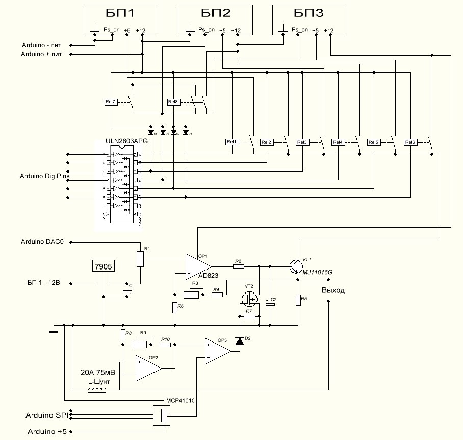
The circuit beats on several functional blocks: ATX power supply kit, PSU switching unit, Arduino D / A voltage amplifier unit, current shunt voltage amplifier unit, and set voltage limiting unit.
BP switching unit: Depending on the voltage set by the user, Arduino chooses which branch to use. Selects the minimum voltage branch, at a minimum of + 3V large specified. 3V remain on the inaccuracy of the voltage setting in the power supply units + ~ 1.2V of the voltage drop at the transitions of the transistor + not a large margin. Simultaneously involved branch key activates this or that power supply. For example, setting 24V, you need to activate all 3 power supplies and connect the output to + 5V of the 3rd in the chain, which will give the output transistor VT1 + 29V on the collector, thereby minimizing the heat output of the transistor.
Voltage Amplifier Unit: Implemented on OP1 operational amplifier. OA is used Rail-to-Rail, unipolar, with a large supply voltage, in my case - AD823. Moreover, the output of the Arduino DAC has a zero point offset = 0.54V. Those. if you set the output voltage = 0, the output will actually be 0.54V. But it does not suit us, because OA amplifies from 0, and the voltage also wants to be adjusted from 0. Therefore, a trimming resistor R1 is applied, which subtracts the voltage. A separate stabilizer on -5V, instead of using -5V branch of the power supply, is used due to the instability of the voltage generated by the power supply, which varies under load. The output of the op-amp is covered by feedback from the output of the VT1; this is done so that the op-amp would compensate for voltage changes depending on the output load.
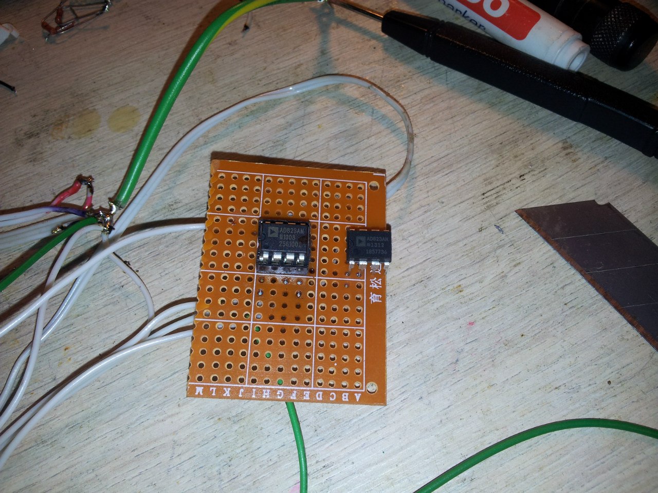
By the way, about AD823 from China on Ebeyu: I was tormented by the day, I could not understand why the scheme does not work from 0 at the input. If more than 1.5V, then everything becomes normal, otherwise the entire supply voltage. Already thinking that he was a fool, he ran into the story of how a person instead of AD823 received a fake from China. Immediately I went to a nearby store, bought it there, set it up and ... lo and behold, everything worked right away. The game, find the differences (fake in the crib, on the right is the original. It's funny that fake looks better):
Next, the voltage amplifier current shunt. Since the current shunt is powerful enough, the voltage drop across it is small, especially at low currents. Therefore, OP2 has been added, which serves to amplify the voltage of the drop in the shunt. Moreover, the speed of the fuse depends on the speed of this opamp.
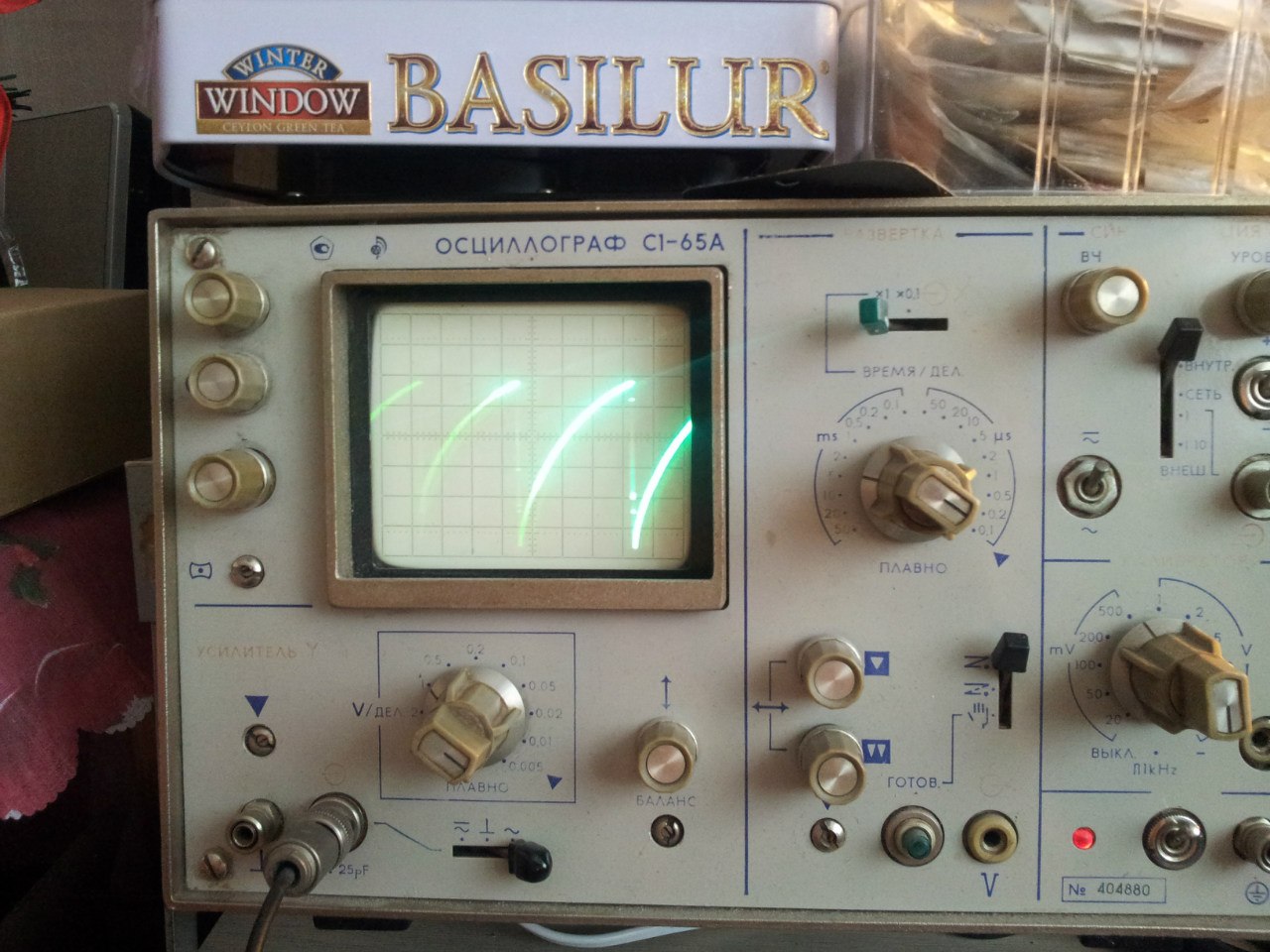
The fuse itself, or rather the current limiting unit, is implemented on the comparator OP2. The amplified voltage corresponding to the current flow is compared with the voltage set by the electronic potentiometer and if it is higher, the VT2 opens with a comparator, and the voltage drops at the base of the output transistor, essentially turning off the output. In operation, it looks like this:
Now to why I have a choke as a shunt. It's simple: as I wrote before - I just forgot to order shunts. And when I had already assembled a block and it became clear, it seemed to wait a long time from China, but it was expensive in the store. Therefore, without hesitation, rummaged in the wiring of old computer power supplies and found chokes, almost exactly fit the resistance. Slightly picked up and set. In addition, it gives protection: In the event of a sudden change in load, the choke smoothes the current for a time sufficient for the current limiter to work. This gives excellent short-circuit protection, but there is also a minus - impulse loads “drive the unit crazy”. However, for me it was not critical.
In the end, I got this power supply:
The inscriptions on the front of the made with LUT. The power supply operation indicators are displayed on a 2-color LED. Where the red is powered from the duty + 5v and show that the unit is ready for operation. A green from Power_Good, and shows that the unit is involved and in good condition. In turn, the transistor decoupling ensures the quenching of the red LED, and if the block has a problem, both the red and the green will go out:
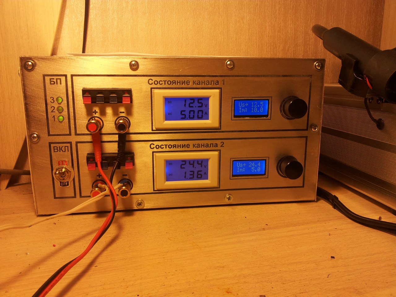
Small screens show the set parameters; large screens show the de facto exit status. Encoder rotation sets the voltage, short press - on / off load, long - select the mode of setting the voltage / maximum current. The current is limited to 12.5A per channel. Really in the amount of 15 is removed. However - on the same element base, with the replacement of power supplies with something 500-watt watt, you can shoot at 20. I don’t know if the sketch code should be given here, the sheet is large and rather dumb, + tails stick out everywhere under the unfinished functionality like correction output voltage on the ADC feedback and adjust the fan speed.
Finally, a couple of words. It turned out that the Arduino DUE when turned on after a long idle may not start to run the program. Those. We turn on the board, we think that our program will now start to run, and in response, silence until you press reset. And all would be nothing, but inside the case reset click a little difficult.
I searched the forum, several people faced the same problem, but they did not find a solution. Wait when the developers fix the problem. I was lazy to wait, so I had to solve the problem myself. And the solution was found to be a primitive disgrace, to solder the electrolytic capacitor at 22µF in parallel to the button. As a result, at the time of launch, while the capacitor is charging, pressing the reset button is simulated. It works fine, it does not interfere with the firmware:
Finally:
In an amicable way, it is necessary to hang temperature sensors on all radiators and adjust the fan speed depending on the temperature, but so far I have been satisfied with the scarf of the fan speed regulator from some FSP power supply unit.
I would also like through the ADC feedback with the switching unit in case of sticky relyushki, as well as feedback on the output, in order to compensate for the temperature drift of the trimming resistors (within 0.1V at high voltages there are deviations).
But the memory buttons and fixed settings from the experience of use seem to be something not necessary.
Now to the point. Formed the requirements for the unit: at least 0-30V, with currents of at least 10A, with adjustable current protection, and with the accuracy of adjustment for voltage 0.1V. And what would become even more interesting - 2 channels, even from the common ground. The voltage setting must be digital, i.e. no variable resistors, only encoders. Fixed voltage settings and memorization are optional.
To indicate the output status, Chinese digital combination indicators were selected on the LCD, with a range of up to 199V with an accuracy of 0.1V and up to 20A with an accuracy of 0.01A. What suits me completely. But what I forgot is to buy shunts for them, because naively thought that they would be included.
For the primary voltage conversion, I thought of using a conventional transformer with taps every 6V, switched by relays from the controller, and a simple emitter follower to adjust the output. And everything would be fine, but when I learned the cost and dimensions of such a transformer (30V * 10A = 300W), I realized that I need to be more modern and use pulsed power supplies.
')
Having run through the sentences I realized that there is nothing sensible about my currents, and if there is, then the toad is categorically against. In this regard, the thought came to try to use computer power supply units, of which there is always plenty of any IT user. 350W blocks were dug out, which promised 22A for + 5V branch and 16A for 12V. Having run through the Internet, I found a lot of controversial opinions about the sequential connection of blocks, and found a clever article on Radiokot how to do it correctly. But before that, I decided to take a chance and still take it and fuck up the blocks together in succession, giving the load.
... And it turned out!
In the photo, 3 blocks are connected in series. De facto at the output of 35V, 10.6A.
Then the question arose: which controller to control. The idea behind ATMega328 here is for the eyes, but DACs ... Considering how much it would cost at least 2 DACs for 12 bits and looking at the characteristics of the Arduino DUE with them on board, as well as comparing the number of required PINs, I realized that it would be easier and cheaper and faster put this arduin into the block entirely, along with the board.
Gradually, the layout was born on the breadboard. I will give it in general, only for one channel:
The circuit beats on several functional blocks: ATX power supply kit, PSU switching unit, Arduino D / A voltage amplifier unit, current shunt voltage amplifier unit, and set voltage limiting unit.
BP switching unit: Depending on the voltage set by the user, Arduino chooses which branch to use. Selects the minimum voltage branch, at a minimum of + 3V large specified. 3V remain on the inaccuracy of the voltage setting in the power supply units + ~ 1.2V of the voltage drop at the transitions of the transistor + not a large margin. Simultaneously involved branch key activates this or that power supply. For example, setting 24V, you need to activate all 3 power supplies and connect the output to + 5V of the 3rd in the chain, which will give the output transistor VT1 + 29V on the collector, thereby minimizing the heat output of the transistor.
Voltage Amplifier Unit: Implemented on OP1 operational amplifier. OA is used Rail-to-Rail, unipolar, with a large supply voltage, in my case - AD823. Moreover, the output of the Arduino DAC has a zero point offset = 0.54V. Those. if you set the output voltage = 0, the output will actually be 0.54V. But it does not suit us, because OA amplifies from 0, and the voltage also wants to be adjusted from 0. Therefore, a trimming resistor R1 is applied, which subtracts the voltage. A separate stabilizer on -5V, instead of using -5V branch of the power supply, is used due to the instability of the voltage generated by the power supply, which varies under load. The output of the op-amp is covered by feedback from the output of the VT1; this is done so that the op-amp would compensate for voltage changes depending on the output load.
By the way, about AD823 from China on Ebeyu: I was tormented by the day, I could not understand why the scheme does not work from 0 at the input. If more than 1.5V, then everything becomes normal, otherwise the entire supply voltage. Already thinking that he was a fool, he ran into the story of how a person instead of AD823 received a fake from China. Immediately I went to a nearby store, bought it there, set it up and ... lo and behold, everything worked right away. The game, find the differences (fake in the crib, on the right is the original. It's funny that fake looks better):
Next, the voltage amplifier current shunt. Since the current shunt is powerful enough, the voltage drop across it is small, especially at low currents. Therefore, OP2 has been added, which serves to amplify the voltage of the drop in the shunt. Moreover, the speed of the fuse depends on the speed of this opamp.
The fuse itself, or rather the current limiting unit, is implemented on the comparator OP2. The amplified voltage corresponding to the current flow is compared with the voltage set by the electronic potentiometer and if it is higher, the VT2 opens with a comparator, and the voltage drops at the base of the output transistor, essentially turning off the output. In operation, it looks like this:
Now to why I have a choke as a shunt. It's simple: as I wrote before - I just forgot to order shunts. And when I had already assembled a block and it became clear, it seemed to wait a long time from China, but it was expensive in the store. Therefore, without hesitation, rummaged in the wiring of old computer power supplies and found chokes, almost exactly fit the resistance. Slightly picked up and set. In addition, it gives protection: In the event of a sudden change in load, the choke smoothes the current for a time sufficient for the current limiter to work. This gives excellent short-circuit protection, but there is also a minus - impulse loads “drive the unit crazy”. However, for me it was not critical.
In the end, I got this power supply:
The inscriptions on the front of the made with LUT. The power supply operation indicators are displayed on a 2-color LED. Where the red is powered from the duty + 5v and show that the unit is ready for operation. A green from Power_Good, and shows that the unit is involved and in good condition. In turn, the transistor decoupling ensures the quenching of the red LED, and if the block has a problem, both the red and the green will go out:
Small screens show the set parameters; large screens show the de facto exit status. Encoder rotation sets the voltage, short press - on / off load, long - select the mode of setting the voltage / maximum current. The current is limited to 12.5A per channel. Really in the amount of 15 is removed. However - on the same element base, with the replacement of power supplies with something 500-watt watt, you can shoot at 20. I don’t know if the sketch code should be given here, the sheet is large and rather dumb, + tails stick out everywhere under the unfinished functionality like correction output voltage on the ADC feedback and adjust the fan speed.
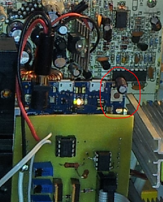
Finally, a couple of words. It turned out that the Arduino DUE when turned on after a long idle may not start to run the program. Those. We turn on the board, we think that our program will now start to run, and in response, silence until you press reset. And all would be nothing, but inside the case reset click a little difficult.
I searched the forum, several people faced the same problem, but they did not find a solution. Wait when the developers fix the problem. I was lazy to wait, so I had to solve the problem myself. And the solution was found to be a primitive disgrace, to solder the electrolytic capacitor at 22µF in parallel to the button. As a result, at the time of launch, while the capacitor is charging, pressing the reset button is simulated. It works fine, it does not interfere with the firmware:
Finally:
In an amicable way, it is necessary to hang temperature sensors on all radiators and adjust the fan speed depending on the temperature, but so far I have been satisfied with the scarf of the fan speed regulator from some FSP power supply unit.
I would also like through the ADC feedback with the switching unit in case of sticky relyushki, as well as feedback on the output, in order to compensate for the temperature drift of the trimming resistors (within 0.1V at high voltages there are deviations).
But the memory buttons and fixed settings from the experience of use seem to be something not necessary.
Source: https://habr.com/ru/post/213497/
All Articles