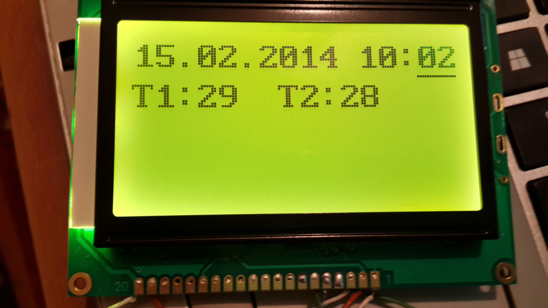
Display programming on ST7920 controller
Hello, I want to talk about programming the display on the ST7920 controller using the ATtiny2313 controller.
Approximate price: $ 15
Display size together with board: 93.0 (Length) × 70.0 (Width) × 13.50 (Height) mm
Size of visible area: 70x38 mm.
The display has 2 operation modes:
In text mode, the display has 4 lines and 16 familiarities per line.
In graphics mode resolution: 128x64 pixels.
')
3 connection modes:
There are 2 modes of operation:
In this post I will talk about:
In order to connect the display to the controller, we need:

Pinout contacts:
GND - Earth
VCC - + 5V
V0 - Contrast setting
RS - Defines the data transfer mode (1 is data, 0 is a command)
RW - Write or read (1 - read, 0 - write)
E - Strobe
D0-D7 - Data Bus
PSB - Determines which data transfer protocol will be used (1 - 8/4 bit bus, 0 - SPI)
BLA - Backlight Anode (+)
BLK - Illumination cathode (-)
In the DB0-DB7 and PB0-PB7 circuit, they are not closed, this is an 8-bit data bus.
The real connection is:
DB0 - PB0
DB1 - PB1
DB2 - PB2
DB3 - PB3
DB4 - PB4
DB5 - PB5
DB6 - PB6
DB7 - PB7
Pinout contacts:
GND - Earth
VCC - + 5V
V0 - Contrast setting
RS - (CS) Start / end data transfer (1 - start, 0 - end)
RW - (SID) Data Bus
E - (SCLK) Strobe
PSB - Determines which data transfer protocol will be used (1 - 8/4 bit bus, 0 - SPI)
BLA - Backlight Anode (+)
BLK - Illumination cathode (-)
RP1 - Contrast Control
RP2 - Brightness Control
And so, from the beginning I will talk about how the display works in general terms.
In order to work with the display, we need to send commands and data to the display.
The commands include: Turning the display on / off, displaying the cursor, moving the cursor, etc. Data includes, for example, characters that you want to see on the display.
Let's look at an example of how initialization is performed for 8 bit mode.
Let's look at an example of how initialization is performed:
That's all, after performing these actions, if you specify in the command to turn on the display to display the cursor, you will see the cursor on the screen.
Consider how to send a single command to the display in 8 bit mode:
To send one byte of data, the exact same thing is done, only high is set at the beginning
RS level.
RS = 0 Team
RS = 1 Data
Here is how one byte of data is sent:
Let's look at the command sending code.
First, let's set the constants so that it would be more convenient:
Command sending function:
Data sending function:
The code used the macro LCD8_MACRO_DELAY, here is its code
Now consider the display initialization commands in text, 8 bit mode:
Based on these four commands, you can write a display initialization function:
After performing the initialization, you should see a flashing cursor on the screen.
Now about the function of receiving a command / data transmission via SPI.
This mode involves 2 lines:
In SPI mode, the transfer of one command or 1 byte of data occurs when transmitting 24 bits
The data transfer protocol is as follows:
This completes the transfer of one byte.
After each transmitted bit, a gate is made, that is:
Consider the function of transmitting the command / data in SPI mode, but first we declare constants:
And now the function itself:
Strobe function:
Now, after you have learned how to initialize the display, you can display any characters on the screen, for example, display the letter A:
And on the display you will see the letter A.
And so, now about how the address space is arranged in text mode:
The screen is divided into 8 columns and 4 lines , in each column you can write 2 ordinary characters or 1 character .
The address space is from 0 to 31.
As you can see, the first line is addresses from 0 to 7
The second line from 16 to 23
The third line from 8 to 15
That is, if you write 16 letters in a row from the address 0, they will be in the first line,
but if you write 17 characters, then the last character will not be on the second line, but on the third!
And finally, for those who want to use the graphics mode, there is such an article: LCD 12864 on the ST7920 controller. Parallel mode (8 bits)
Link to library file
Display Specifications
Approximate price: $ 15
Display size together with board: 93.0 (Length) × 70.0 (Width) × 13.50 (Height) mm
Size of visible area: 70x38 mm.
The display has 2 operation modes:
- Graphic
- Text
In text mode, the display has 4 lines and 16 familiarities per line.
In graphics mode resolution: 128x64 pixels.
')
3 connection modes:
- Connection via 8 bit bus
- 4-bit bus connection
- SPI Connections (3 Bit Bus)
There are 2 modes of operation:
- Normal: 450 µA intake, 5 V
- Sleep mode: 30 µA intake, 5 V
In this post I will talk about:
- Work in text mode
- Connections and programming on an 8 bit bus
- SPI Connections and Programming
In order to connect the display to the controller, we need:
- Display on ST7920 controller
- 2 subscriber resistors for 10 kΩ.
- For 8 bit mode, 4.7 kΩ resistor (or more)
- ATtiny2313 controller
- Power supply 5V.
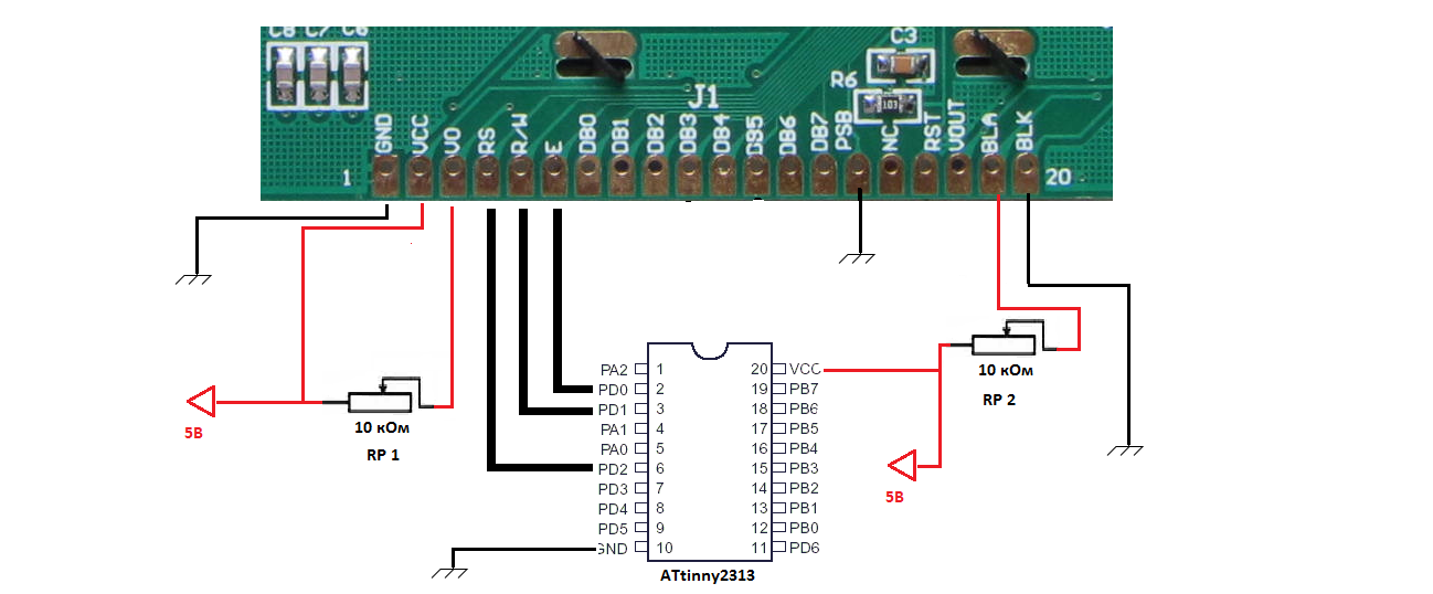
Wiring diagram
Connection via 8 bit data bus
Pinout contacts:
GND - Earth
VCC - + 5V
V0 - Contrast setting
RS - Defines the data transfer mode (1 is data, 0 is a command)
RW - Write or read (1 - read, 0 - write)
E - Strobe
D0-D7 - Data Bus
PSB - Determines which data transfer protocol will be used (1 - 8/4 bit bus, 0 - SPI)
BLA - Backlight Anode (+)
BLK - Illumination cathode (-)
In the DB0-DB7 and PB0-PB7 circuit, they are not closed, this is an 8-bit data bus.
The real connection is:
DB0 - PB0
DB1 - PB1
DB2 - PB2
DB3 - PB3
DB4 - PB4
DB5 - PB5
DB6 - PB6
DB7 - PB7
SPI connection
Pinout contacts:
GND - Earth
VCC - + 5V
V0 - Contrast setting
RS - (CS) Start / end data transfer (1 - start, 0 - end)
RW - (SID) Data Bus
E - (SCLK) Strobe
PSB - Determines which data transfer protocol will be used (1 - 8/4 bit bus, 0 - SPI)
BLA - Backlight Anode (+)
BLK - Illumination cathode (-)
Trimmer Resistors
RP1 - Contrast Control
RP2 - Brightness Control
Display programming protocol description
8 bit mode
And so, from the beginning I will talk about how the display works in general terms.
In order to work with the display, we need to send commands and data to the display.
The commands include: Turning the display on / off, displaying the cursor, moving the cursor, etc. Data includes, for example, characters that you want to see on the display.
Let's look at an example of how initialization is performed for 8 bit mode.
Let's look at an example of how initialization is performed:
- A delay of 50 µs.
- Send the command to install 8 bit mode.
- The delay is 120 µs.
- We send the command to turn on the display (it also indicates whether to turn on the cursor and whether to blink the cursor)
- A delay of 50 µs.
- Re-send the installation function of the 8 bit mode
- The delay is 120 µs.
- Send a command to clear the screen
- The delay is 20 µs.
- Set the ENTRY MODE (this command tells us which way to move the cursor after writing the character, we need to the right, respectively)
That's all, after performing these actions, if you specify in the command to turn on the display to display the cursor, you will see the cursor on the screen.
Consider how to send a single command to the display in 8 bit mode:
- Set Low E
- Set RS low
- Low RW
- Delay 1 µs.
- Set high level E
- Sent to the data port byte command
- Delay 1 µs.
- Set Low E
- 50 µs delay.
To send one byte of data, the exact same thing is done, only high is set at the beginning
RS level.
RS = 0 Team
RS = 1 Data
Here is how one byte of data is sent:
- Set Low E
- Set RS High
- Low RW
- Delay 1 µs.
- Set high level E
- Sent to the data port byte command
- Delay 1 µs.
- Set Low E
- 50 µs delay.
Let's look at the command sending code.
First, let's set the constants so that it would be more convenient:
.equ PCom = PORTD ; RS, RW, E .equ PW = PORTB ; .equ RS = 2 ; PCom RS .equ E = 0 ; PCom E .equ RW = 1 ; PCom RW .def Data = R18 ; Command sending function:
; Data LCD12864_CommandOut: ; . cbi PCom, E ; E cbi PCom, RS ; RS cbi PCom, RW ; RW LCD8_MACRO_DELAY 1, 1 ; 1 . sbi PCom, E ; E out PW, Data ; LCD8_MACRO_DELAY 1, 1 ; 1 . cbi PCom, E ; E LCD8_MACRO_DELAY 1, 50 ; 50 . Ret Data sending function:
; Data LCD12864_DataOut: ; . sbi PCom, E ; E cbi PCom, RS ; RS cbi PCom, RW ; RW LCD8_MACRO_DELAY 1, 1 ; 1 . sbi PCom, E ; E out PW, Data ; LCD8_MACRO_DELAY 1, 1 ; 1 . cbi PCom, E ; E LCD8_MACRO_DELAY 1, 50 ; 50 . Ret The code used the macro LCD8_MACRO_DELAY, here is its code
; .MACRO LCD8_MACRO_DELAY ; 1 , 2 , ldi Temp, @0 ldi Temp1, @1 rcall LCD12864_Delay .ENDM ; 4 . ; 2 : ;R16 – ;R17 – R16 . LCD12864_Delay: push R16 ; . ES0: dec R16 ;- . cpi R16, 0 ;? brne ES0 ; - . pop R16 ;? . dec R17 ; " " . cpi R17, 0 ; = 0? brne LCD12864_Delay ret Now consider the display initialization commands in text, 8 bit mode:
FUNCTION SET command: 0 0 1 DL 0 RE 0 0
DL:
- If set to 1, then set 8 bit data transfer
- If 0 is set, then 4 bits are set.
RE:
- If 1 is set then the set of extended commands is set.
- If set to 0, the set of basic commands is set.
The next command is DISPLAY STATUS: 0 0 0 0 1 DCB
D:
- If 1 is set then the display is on
- If set to 0, the display is off
WITH:
- If 1 is set then the cursor is on
- If set to 0 then the cursor is off
B:
- If set to 1 then the cursor will flash
- If set to 0 then the cursor will not flash
The next command is a simple CLEAR - screen cleanup: 0 0 0 0 0 0 0 1
And the last command is ENTRY MODE SET - setting the direction of the cursor movement: 0 0 0 0 0 1 I / DS
- If I / D = 1 then the cursor moves to the right.
- If I / D = 0 then the cursor moves to the left
Based on these four commands, you can write a display initialization function:
LCD12864_Init: ; . LCD8_MACRO_DELAY 1, 50 ; 50 . Ldi Data, 0b00110000 rcall LCD12864_CommandOut ; 8 . LCD8_MACRO_DELAY 1, 120 ; 120 . Ldi Data, 0b00001111 rcall LCD12864_CommandOut ; , , LCD8_MACRO_DELAY 1, 50 ; 50 . Ldi Data, 0b00110000 rcall LCD12864_CommandOut ; 8 . LCD8_MACRO_DELAY 1, 120 ; 120 . Ldi Data, 0b00000001 rcall LCD12864_CommandOut ; LCD8_MACRO_DELAY 1, 20 ; 20 . Ldi Data, 0b00000110 rcall LCD12864_CommandOut ; LCD8_MACRO_DELAY 1, 50 ; 50 . ret After performing the initialization, you should see a flashing cursor on the screen.
SPI mode
Now about the function of receiving a command / data transmission via SPI.
This mode involves 2 lines:
- SID is a contact of data transfer, on the display it is also RW
- SCLK is the strobe line, aka E on the display.
- CS is the start / end of data transfer, on the display it's RS
In SPI mode, the transfer of one command or 1 byte of data occurs when transmitting 24 bits
The data transfer protocol is as follows:
- Set high CS
- We transfer 4 units in a row
- Transmit 1 bit RW - read or write
- Transmit 1 RS bit - Command or data
- Pass 0
- Transmit 4 bits of the high half of the data byte.
- Pass 4 zeros
- Transmit 4 bits of the lower half of the data byte.
- Pass 4 zeros in a row
- Set CS low
This completes the transfer of one byte.
After each transmitted bit, a gate is made, that is:
- Delay 1 µs.
- Set High SCLK
- Delay 1 µs.
- Set SCLK low
- Delay 1 µs.
Consider the function of transmitting the command / data in SPI mode, but first we declare constants:
.equ PCom = PORTD ; SID SCLK .equ SID = 1 ; RW .equ SCLK = 0; E .equ CS = 2; RS / .def Data = R18 ; And now the function itself:
/************************************* LCD12864_CommandOut - LCD12864_DataOut - Data **************************************/ LCD12864_CommandOut: ldi r20, 0 rjmp command LCD12864_DataOut: ldi r20, 1 command: LCD8_MACRO_DELAY 1, 1 sbi PCom, CS ; sbi PCom, SID ; SID 1 ; 4 rcall strob ; 1 rcall strob ; 1 rcall strob ; 1 rcall strob ; 1 rcall strob ; 1 ; rw cbi PCom, SID ; rw = 0 rcall strob ; , . cbi PCom, SID ; rs = 0 cpi r20, 0 breq command1 sbi PCom, SID ; rs = 1 command1: rcall strob ; 0 cbi PCom, SID ; 0 rcall strob ; ldi r20, 8 ; for_send_data: cpi r20, 0 ; ? breq stop_send_data ; cpi r20, 4 ; , 4 4 . brne no_strob ; ; 4 cbi PCom, SID rcall strob rcall strob rcall strob rcall strob ; no_strob: dec r20 ; rol Data ; 1 brcs send_bit_1 ; 1, C , 1 ; , 0 cbi PCom, SID ; 0 rcall strob rjmp for_send_data ; 1 send_bit_1: sbi PCom, SID ; 1 rcall strob rjmp for_send_data stop_send_data: ; , 4 cbi PCom, SID rcall strob rcall strob rcall strob rcall strob cbi PCom, SID cbi PCom, CS ; ret Strobe function:
strob: LCD8_MACRO_DELAY 1, 1 ; 1 sbi PCom, SCLK ; SCLK LCD8_MACRO_DELAY 1, 1 ; 1 cbi PCom, SCLK ; SCLK LCD8_MACRO_DELAY 1, 1 ; 1 ret .endif ;****************************************************** Text mode
Now, after you have learned how to initialize the display, you can display any characters on the screen, for example, display the letter A:
ldi Data, 'A' rcall LCD12864_DataOut And on the display you will see the letter A.
And so, now about how the address space is arranged in text mode:
The screen is divided into 8 columns and 4 lines , in each column you can write 2 ordinary characters or 1 character .
The address space is from 0 to 31.
| 0 | one | 2 | 3 | four | five | 6 | 7 |
| sixteen | 17 | 18 | nineteen | 20 | 21 | 22 | 23 |
| eight | 9 | ten | eleven | 12 | 13 | 14 | 15 |
| 24 | 25 | 26 | 27 | 28 | 29 | thirty | 31 |
As you can see, the first line is addresses from 0 to 7
The second line from 16 to 23
The third line from 8 to 15
That is, if you write 16 letters in a row from the address 0, they will be in the first line,
but if you write 17 characters, then the last character will not be on the second line, but on the third!
There is a special command to set the cursor address: 1 AC6 AC5 AC4 AC3 AC2 AC1 AC0
With this command, you can put the cursor in the right place by entering the address from 0 to 31 for the place AC0-AC6.
Graphic mode
And finally, for those who want to use the graphics mode, there is such an article: LCD 12864 on the ST7920 controller. Parallel mode (8 bits)
Library to work with ST7920
Link to library file
Source: https://habr.com/ru/post/213459/
All Articles