Weather station with Ethernet and tablet as a display device
Introduction
I am a user of domestic weather stations with experience, and in this lies a double catastrophe. Firstly, I have become so accustomed to the fact that the weather inside and outside the house is known to me, that the absence of this information puts me in a state of cognitive dissonance. Secondly, I am chronically unlucky with weather stations. Two of them broke down and, as in such cases they talk about all kinds of indicator devices, they began to “show the weather”, only to the contrary, they showed anything, but not the weather. From the States I brought with me the third one, which served me faithfully and faithfully for a year, and I started to relax slowly, but then the accidental runners (and giving my wife and I the opportunity to temporarily take care of my son and run out of the house) parents an attack of forced care, in turn, caused a keen desire to wash the windows. The result of careful rubbing of the windows is not only sparkling windows, but also a weather station sensor jumping down. The second floor, so that the sensor would hardly have crashed, but, as is known, there is an invisible space-time singularity directly under the windows of each high-rise building. I don’t know if this phenomenon can be described in the framework of the Standard Model, but that there is no doubt that the principle of “what fell, is gone” is at the basis of the singularity. So I did not find the sensor.
Naturally, the need to change the device arose to its full height, but the thought that none of the “ex” had lasted more than a year at my house was alarming. And then the idea came to my mind: “shouldn’t I do it myself?”.
Prerequisites for such a development were. Technical education made it possible to soberly assess their own strength, a rich radio amateur childhood gave hope that they could cope not only with the software part - with hardware, at least, with primitive ones, there shouldn't be any problems either. In addition, unlike the purchased stations, the maintainability of a self-made solution is much higher, and I generally keep quiet about customization.
Initially, the idea was to create a certain number of temperature and humidity sensors located in different parts of the home and on its outer walls, and the central unit. Sensors had to take the data and transfer it to the central unit, which, in turn, had to visualize it. As a side functionality, we considered the possibility of sending data via Ethernet to an existing server for the purpose of building statistics (I like to see "how it was") and the subsequent transfer to home-based gadgets such as iPads, iPhones, androids and other evil spirits.
Very quickly (namely, at the stage of exploring the possibilities of not very expensive microcontrollers and commercially available peripherals), the idea of visualization on the central unit died out, so the option of sending to the server followed by visualization on improvised devices acquired the status of head.
As a platform for the implementation of the idea was chosen Arduino. The reasons: a developed infrastructure, a lot of examples, a lot of components for sale, price (if we talk about Chinese mirror clones, and not genuine Arduino), availability (good on Ebay, you can find them in many and for every taste). In principle, all the same could be implemented on bare controllers, but, given the fact that I only entered the technology, I didn’t want to increase the existing entry threshold. The only thing, though the weather sensor and not an aesthetic device, didn’t want to hang a coffin with a linear size of 20 cm on the wall, so the Arduino Pro Mini was chosen as the basis, and not some impressive Uno size.
')
So, conceptually, the system consists of four parts:
- Weather sensors. The task is to measure the weather and send data via radio to the central unit
- Central unit. The task is to receive weather data, wrap it in HTTP and post it to the server
- Server. The task is to receive data from the central unit, save it in the database and transfer it in a form suitable for visualization on all kinds of home gadgets.
- Visualization devices. The task is to show the weather to the user.
Exchange protocol
Before proceeding to the description of the components of the system should be a brief excursion into the protocol and the principle of data exchange in the radio. The radio is based on the VirtualWire library, which already has the means of “correct” transmission, such as Manchester coding and checksum verification. A microprotocol with a fixed packet structure was implemented on top of this library. Each packet consists of three fields — the transmitting device address (uint16), the sensor type (int16), and the data (float). There is no additional verification of the correctness of the incoming data, except for checking the packet length, since the additional security measures are implemented on the server side, where data will eventually end up. The address of the transmitting device is generated randomly when the device is turned on, if it has not been previously generated, and is written to the EEPROM. Each device has the right to transmit arbitrarily many readings of sensors of different types. So, each weather sensor transmits two packages - packages with temperature readings and humidity readings.
Thus, a radio network is organized with a “common bus” topology, but without any high-level capabilities like collision detection and delivery guarantees. If two devices attempt to transmit data simultaneously, the data is lost as a result of a collision.
The implementation of the microprotocol was framed into a separate library containing two main methods, send and receive. All other methods - service, necessary, for example, to generate the address of the transmitting device.
Library source code
// This library is free software; you can redistribute it and/or // modify it under the terms of the GNU Lesser General Public // License as published by the Free Software Foundation; either // version 2.1 of the License, or (at your option) any later version. // Created by Andrey Filimonov 2014 #ifndef WIRELESSSENSORPIPE_H #define WIRELESSSENSORPIPE_H #if ARDUINO >= 100 #include "Arduino.h" #else #include "WProgram.h" #endif class WirelessSensorPipe { public: enum SensorType { TEMPERATURE = 0, HUMIDITY, PRESSURE, WATERFLOW, HEATERSETPOINT, HEATERFLAMEENABLED, HEATERRWTEMPERATURE, HEATERTARGETROOMTEMPERATURE }; struct Packet { int16_t id; SensorType type; float value; }; private: Packet data; int16_t _id; public: void begin(uint16_t transmitPin, uint16_t receivePin, uint16_t pttPin = 10, uint16_t eepromAddress = 0); void send(SensorType type, float value); bool receive(Packet& packet, uint16_t timeout = 30000); int16_t id() {return _id;}; private: void EEPROMWriteInt(int p_address, int16_t p_value); int16_t EEPROMReadInt(int p_address); }; #endif // This library is free software; you can redistribute it and/or // modify it under the terms of the GNU Lesser General Public // License as published by the Free Software Foundation; either // version 2.1 of the License, or (at your option) any later version. // Created by Andrey Filimonov 2014 #include "WirelessSensorPipe.h" #include "VirtualWire.h" #include "EEPROM.h" //#define DEBUG void WirelessSensorPipe::EEPROMWriteInt(int p_address, int16_t p_value) { byte lowByte = ((p_value >> 0) & 0xFF); byte highByte = ((p_value >> 8) & 0xFF); EEPROM.write(p_address, lowByte); EEPROM.write(p_address + 1, highByte); } int16_t WirelessSensorPipe::EEPROMReadInt(int p_address) { byte lowByte = EEPROM.read(p_address); byte highByte = EEPROM.read(p_address + 1); return ((lowByte << 0) & 0xFF) + ((highByte << 8) & 0xFF00); } void WirelessSensorPipe::begin(uint16_t transmitPin, uint16_t receivePin, uint16_t pttPin, uint16_t eepromAddress) { // Initialise the IO and ISR vw_set_rx_pin(receivePin); vw_set_tx_pin(transmitPin); vw_set_ptt_pin(pttPin); vw_setup(256); // Bits per sec vw_rx_start(); // Start the receiver PLL running _id = EEPROMReadInt(eepromAddress); if (_id <= 10000) { randomSeed(analogRead(0)); _id = random(10000, 60000); EEPROMWriteInt(eepromAddress, _id); } } void WirelessSensorPipe::send(SensorType type, float value) { data.id = _id; data.type = type; data.value = value; vw_send((uint8_t *)&data, sizeof(Packet)); vw_wait_tx(); // Wait until the whole message is gone } bool WirelessSensorPipe::receive(Packet& packet, uint16_t timeout) { bool result = false; uint8_t message_length = sizeof(Packet); if (vw_wait_rx_max(timeout) && vw_get_message((uint8_t*)&data, &message_length) && message_length == sizeof(Packet)) { packet.id = data.id; packet.type = data.type; packet.value = data.value; result = true; } return result; } Weather sensors
It seemed that making a weather sensor was a simple matter. With the existing MK (I’m reminding it the ATMega328 as part of the Arduino Pro Mini) we hook the temperature and humidity sensor (in the project it was DHT11), we hook the OOK transmitter at 433 MHz, we make a software pump, which pumps the data from the sensor, pumps it into the transmitter, and that's it done by How to connect DHT11 to Arduino I will not describe, materials of this kind are full, including on Habré ( http://habrahabr.ru/post/171525/ , http://habrahabr.ru/post/184966/ ). Connecting an OOK 433 MHz transmitter is also not a problem ( http://habrahabr.ru/post/210830/ ). The DHT from Adafruit is used to obtain data (a set of libraries can be found here: https://github.com/adafruit ). For communication, the described microprotocol is used.
Everything would be simple if it were not for the perfectionism. The fact is that the conviction has taken root in the brain that the sensor should work on batteries and should work for a long time. And here lay the ambush, because the Arduino in its initial state, if no action is taken, consumes about 50mA. The optimistic capacity of a typical AAA battery is 1200mAh. With such an appetite, the battery pack will last for 24 hours. Since the idea of changing the batteries in every sensor once a day didn’t excite me, I started to break free, studying the energy saving modes of Atmel controllers. In addition to software tricks, it was necessary to do something with the periphery, namely with the DHT11 and the transmitter. So that they do not constantly suck out the battery, it was decided to connect them + 5V not to the power bus, but to a separate leg of the Arduino. This would allow the inclusion of peripherals only when needed. And since it doesn’t make sense to transmit weather data more than once every 5 minutes, the periphery is needed once every 5 minutes for a few seconds. According to the specifications, the ATmega328 is able to feed 40mA through its pins, on the other hand, the transmitter consumption is 30ma, the DHT11 consumption is much less, plus they never work at the same time, first the data from the sensor is read, then they are transmitted. So 40mA should be more than enough. To summarize, there are three consumers in the device:
- Peripherals (virtually dealt with it, powered from a separate leg)
- The microcontroller itself (here you need to deal with energy saving)
- Unnecessary peripherals on the Arduino board (for example, a power LED that indicates power)
The LED and voltage converter from + 6.5V ... 12V to 5V, present on the Arduino board and necessary, if you want to power it with anything, as long as it was anything more than 12V, were amputated immediately, since the sensor was powered in the form of three batteries AAA with a total voltage of 3.7V ... 5.1V (depending on the degree of freshness), so that the buck converter comes to nothing. I don’t need an LED either; nobody sees him inside the case anyway. Hurray, surgery led to a decrease in appetite almost doubled - up to 28mA. But it's still a lot. Since by the time of measurement the power supply of the periphery was already carried out from the MK leg and was turned off at that time, it was concluded that 28mA is the appetite of the controller itself. You can jam it only by software. Many instructions and guides have been read. Most of all knowledge contains this . Skipping the ordeals with energy saving, I would say that switching on the power saving mode SLEEP_MODE_PWR_DOWN with the output from it by triggering the watchdog timer, turning off the analog-digital converter and turning off the detection of the operating mode with an unacceptably low supply voltage (the so-called brown-out mode) helped the most. If you manage only the first two points from my list for turning an energy fat man into an anarexic, then the consumption will be about 20uA. This is a thousand times less than the original 28mA, and in principle, one could stop at that, but the ATmega328 datasheet says that when the microcontroller is not busy, it can consume less than 1uA!
Inside the MK, different devices react differently to a drop in the supply voltage. So as the supply voltage decreases, you may get a situation where the main part of the crystal is working, and some devices are not, or they are unstable, or not as they should. To avoid such iron deficiency, the MC can detect a power supply drop below a critical level and shut down completely. However, this opportunity, as it turned out, requires quite considerable power. Turning off the brown-out led to the fact that my Chinese DT838 multimeter in the measurement mode of microampere currents showed that it does not feel anything. Here it is! It is hardly possible to say that the current has become less than 1uA, but it has definitely become less than the sensitivity threshold of the microammeter, which, in turn, is obviously less than 20uA. Since the accuracy of the measurements did not allow to train further, it was decided to consider the result as satisfactory and to finish the research on energy consumption.
So, the sensor has been assembled, inside is wired up a code that implements the same pump, which turns on every 5 minutes and goes into a deep sleep the rest of the time. A receiver for the transmitted data was assembled on the mockup. Everything was powered and ... Usually in such places after the ellipse they write some unexpected epic file, but no, everything went smoothly, the test receiver began to receive data and the data looked quite adequate: temperature - 25 degrees, humidity - 40%. Cheers, comrades! It is done. For interest, it was decided to place the devices in conditions close to the field, namely to increase the distance between the transmitter and receiver from 10cm to 5m. And here came the epic file. In direct line of sight, at a distance of 5m, the receiver did not register anything. I was ready for this turn of events and thought that I knew what was going on. The fact is that neither the receiver nor the transmitter at that time possessed an antenna. By all the rules, a pair of quarter-wave antennas were measured and cut off (for 433 MHz, this is approximately 17.5 cm of wire). The conductors were sealed in place of the antennas and a miracle, the transmission went! The next step is to eliminate direct visibility by placing a wall of gas silicate 375 mm thick between the receiver and the transmitter. And again the trouble, the transfer that is, it is not. Dances with the location of devices, antennas, their form, internals (stranded wire, single-core, in different isolations (why?)) Did not lead to anything. Reducing the transfer rate to a ridiculous 256 bit / s did not greatly improve the situation. In an attempt to brand the antennas and my lack of knowledge in the field of radiophysics led to the involvement in the process of three people with a radio physical education, one of whom is a Ph.D. All the choir said something like "the antenna has nothing to do with, these transmitters, provided the signal is correctly encoded, work with any garbage that is attached as an antenna, you must have done something special so that they do not work within 10 meters" . After chewing sarcasm and striking that the encoding is correct, because VirtualWire uses Manchester code with additional checks on top of it, I began to think what I could do wrong. If we discard all seemingly obvious, but still incredible assumptions that defective transmitters or receivers caught me (I had five sets, I tried them, the result is the same), only one version remained - I am under-powered the transmitter. For experimental purposes, I transferred the power of the transmitter from the MK's foot to the + 5V bus and voila, there is data on the receiver. And they are regardless of the position in which the antenna is, what it is made of and where the receiver and transmitter are located within the house. The only circumstances in which I managed to force the transmission to stop is to cover the transmitter with an iron cap (but this is already from the “aaaaa” series, said the harsh Siberian men ”). Besides, after thinking for 10 seconds (why didn’t I do it before?), I realized that the OOK transmitter does not eat anything when it does not transmit anything, so it does not make sense to save the battery from it in some “external” way. Time for the version of why the transmitter is poorly powered by the MK leg. I do not have any formally confirmed theory on this score, without an oscilloscope, which I do not have, it is probably impossible to find out exactly, but the working hypothesis is as follows. 30mA, declared for the transmitter by the valiant Chinese, can mean anything. For example, the average consumption during the transfer of any test sequence. In this case, the peak consumption, with the transfer of the unit can be anything, including more than 40mA. On the other hand, I am sure that the 40mA declared for the MK output is exactly the upper limit, beyond which nothing is guaranteed. So it is quite possible that the peak consumption of the transmitter could easily be more than the capabilities of the MC. It is worth noting that out of two weeks of designing the sensor (initially planned a couple of days) I spent 90% of the time to solve problems with the transmitter.
The trivial circuitry looks like this:

Sensor source code
#include <avr/sleep.h> #include <avr/wdt.h> #include <DHT.h> #include <VirtualWire.h> //workaround for the stupid arduino problem of not being able to include a library from another library, so i'm including the libs needed by WSP here #include <EEPROM.h> #include <WirelessSensorPipe.h> //#define DEBUG #define KIDROOM //#define OUTDOOR /* hardware configuration */ #define ACCESSORIESPOWERPIN 3 #define DHTPIN 4 #define TRANSMITPIN 2 #if defined (KIDROOM) #define DHTTYPE DHT22 #define TCORRECTION (0) #define HCORRECTION (0) #elif defined (OUTDOOR) #define DHTTYPE DHT22 #define TCORRECTION (0) #define HCORRECTION (0) #endif #ifdef DEBUG #define SLEEPDURATION 0 //sleep duration in seconds, shall be a factor of 8 #else #define SLEEPDURATION 320 //sleep duration in seconds, shall be a factor of 8 #endif DHT dht(DHTPIN, DHTTYPE); void sleepFor8Secs() { // disable ADC ADCSRA = 0; // clear various "reset" flags MCUSR = 0; // allow changes, disable reset WDTCSR = bit (WDCE) | bit (WDE); // set interrupt mode and an interval WDTCSR = bit (WDIE) | bit (WDP3) | bit (WDP0); // set WDIE, and 8 seconds delay wdt_reset(); // pat the dog set_sleep_mode (SLEEP_MODE_PWR_DOWN); sleep_enable(); // turn off brown-out enable in software MCUCR = bit (BODS) | bit (BODSE); MCUCR = bit (BODS); sleep_cpu (); // cancel sleep as a precaution sleep_disable(); } // watchdog interrupt ISR (WDT_vect) { wdt_disable(); // disable watchdog } // end of WDT_vect WirelessSensorPipe pipe; void setup () { #ifdef DEBUG Serial.begin(9600); Serial.println("Entered setup"); #endif dht.begin(); pinMode(ACCESSORIESPOWERPIN, OUTPUT); pipe.begin(TRANSMITPIN, 0); #ifdef DEBUG Serial.print("Sensor id:"); Serial.print(pipe.id()); #endif } void loop() { pinMode(ACCESSORIESPOWERPIN, OUTPUT); digitalWrite(ACCESSORIESPOWERPIN, HIGH); //turn on the DHT sensor and the transmitter delay(2000); //sleep till the intermediate processes in the accessories are settled down float humidity = dht.readHumidity() + HCORRECTION; float temperature = dht.readTemperature() + TCORRECTION; digitalWrite(ACCESSORIESPOWERPIN, LOW); // turn off the accessories power pinMode(ACCESSORIESPOWERPIN, INPUT); //change pin mode to reduce power consumption #ifdef DEBUG Serial.print("Humidity: "); Serial.println(humidity); Serial.print("Temperature: "); Serial.println(temperature); /* blink the LED to indicate that the readings are done */ digitalWrite(13, HIGH); delay(100); digitalWrite(13, LOW); #endif pipe.send(WirelessSensorPipe::TEMPERATURE, temperature); delay(1000); pipe.send(WirelessSensorPipe::HUMIDITY, humidity); for (int i = 0; i < SLEEPDURATION / 8; i++) sleepFor8Secs(); } The attentive reader will notice that the firmware has made it possible to introduce corrections for data read from DHT. The fact is that DHT11, as it turned out, has a number of drawbacks, namely: accuracy to whole degrees, extremely poor calibration and repeatability of results from measurement to measurement and from sensor to sensor. So two DHT11s standing nearby can show temperature with a difference of two degrees, which did not suit me. In addition, looking ahead to the topic of the next article, I will say that my house is heated by a boiler, which at that moment was controlled by hands, i.e. we based on the situation on the street exhibited the desired boiler power. Almost all modern boilers have the ability to control, at least in the on / off mode. So the next project is to use the available data on the temperature outside and in the rooms for temperature control of the situation inside the room. For this purpose, it is very rough to measure the temperature inside the room with an accuracy of a degree; such rudeness leads to self-oscillations in the temperature control system. So it was decided to replace DHT11 with much more expensive DHT22, which do not require any corrections (two DHT22 standing in one place coincide in readings up to one-tenth of a degree) and ten times more accurate.
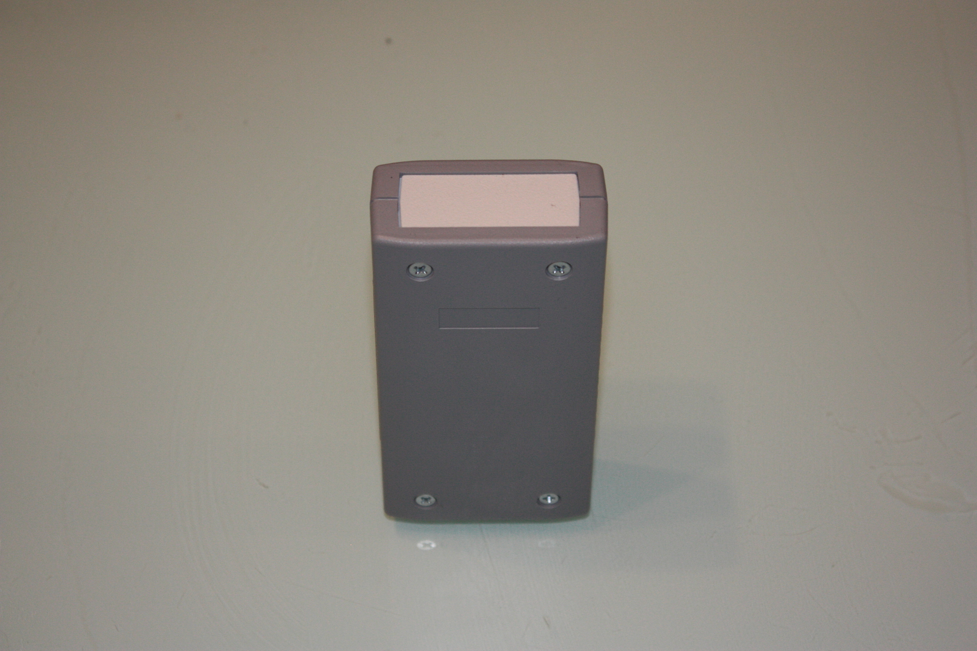
Sensor photos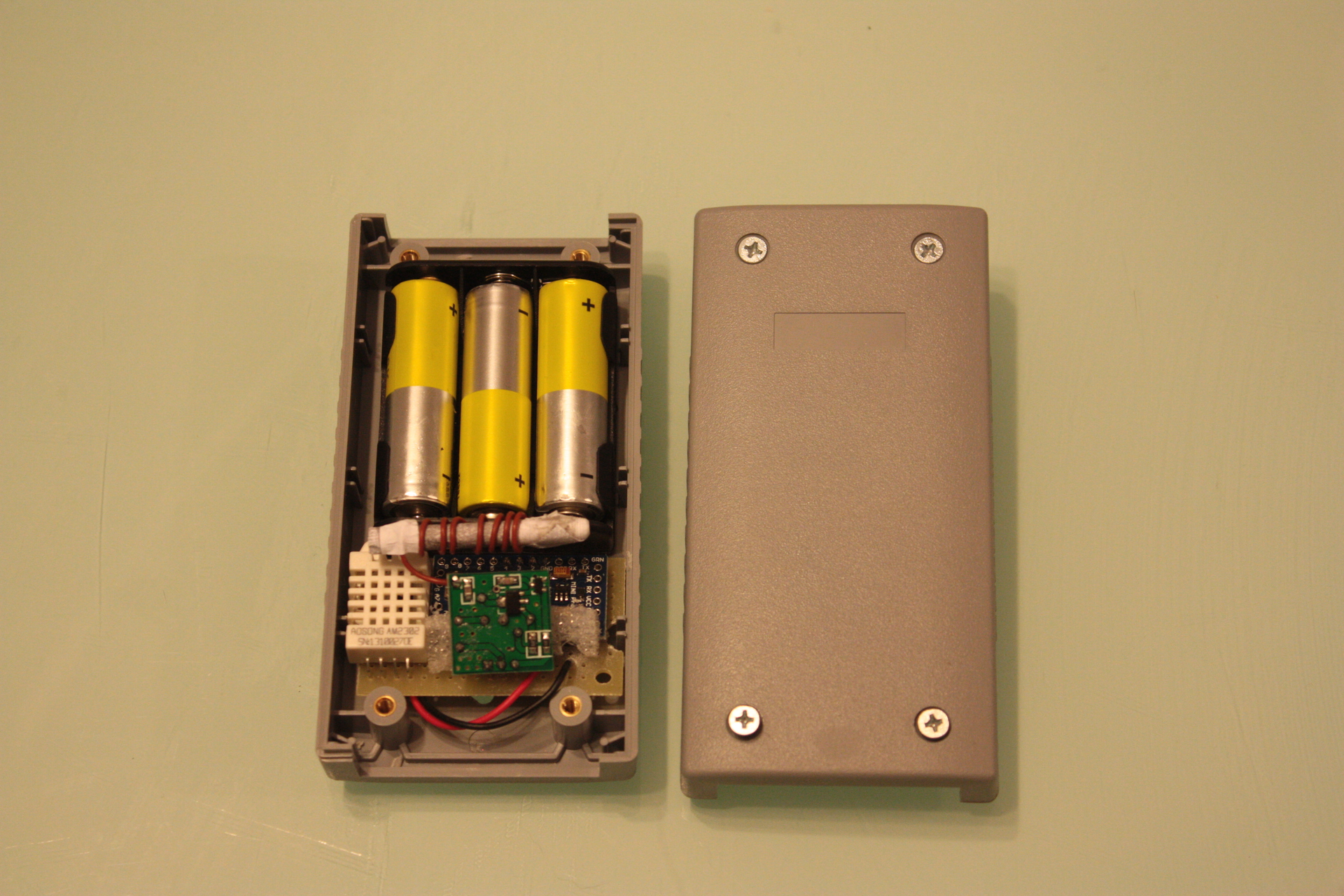

Central unit
So, weather data is available on the air. The question is what to do with them next. And then they need to catch, encapsulate in HTTP and transfer to storage in the server at home. To this end, it was decided to make a central unit equipped with an Arduino Nano, a 433 MHz superregenerative receiver and an ENC28J60 Ethernet module. Using Nano instead of Pro Mini was dictated by the presence of a 3V3 converter on the Nano board, and ENC28J60, despite its tolerance to + 5V on information pins, still requires power to 3V3.
The scheme looks like this:
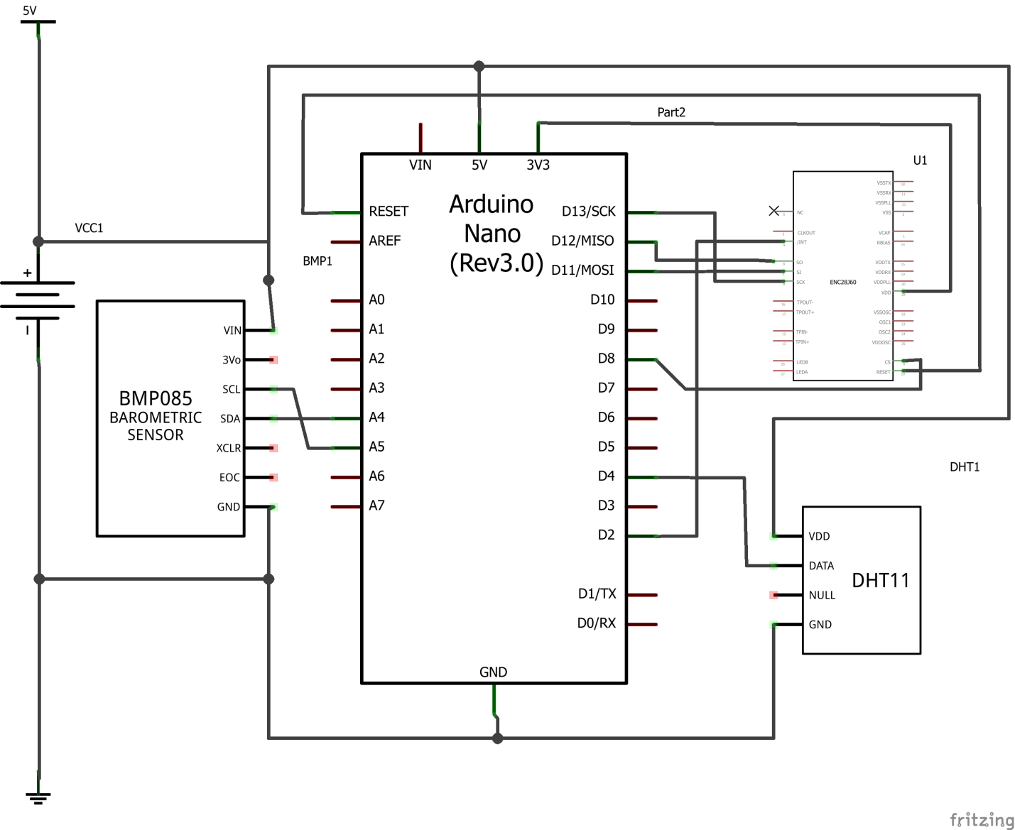
As can be seen, in addition to ENC28J60, the circuit also contains a DHT sensor (ultimately, this is DHT22) for temperature / humidity removal at the location of the central unit and the BMP085 sensor used for measuring pressure. From the features of the hardware implementation, it is worth noting that BMP085 are different, the sensor itself is powered by 3V3, but I bought 5V-> 3V3 with a built-in converter, so that it could be powered by both voltages. In the case of the Nano, this is irrelevant, because it has its own converter, but in the case of using the Pro Mini it would be a useful feature.
There were no surprises with the hardware part, but with the software part - more than enough. Surprises connected to the ethernet controller. Firstly, it differs from the W5100 ENC28J60 widely used in Ethernet-shields in that it does not contain the TCP / IP hardware implementation, the stack is implemented programmatically, with a library for working with this chip. Secondly, the whole community-experience is centered around the implementation of primitive HTTP servers on Arduino, I have the opposite task, to make an Arduino- “browser”, which through HTTP GET would send the data to the server. Attempting to implement such a browser ran into a decent amount of difficulty. Despite the fact that the ethercard library defines the browseUrl method, which does what is needed, its work is not very stable. By itself, the method only means a request to the library to form a GET request. In order to execute the request itself, you need to define a callback method that is called upon receiving data from the server and after accessing the browseURL, call the packetLoop method, which performs the direct traffic pumping. So, theoretically, the work on sending a message consists of two stages: a single call to the browseUrl and a multiple call to the packetLoop to pump the request and receive a response. It is completely incomprehensible how many times you need to pull the packetLoop. No status method returns. The input is the length of the packet, which can be determined by calling the packetReceive method. The first thought was that you need to pull the packetReceive and packetLoop until the packetReceive returns non-zero. But no, firstly, immediately after a browseUrl call, multiple calls to packetReceive return zero. Secondly, after the appearance of the first non-zero, there may be a series of zeroes, then again non-zero. Since the answer from the server is not interesting to me, the main problem is to call the packetLoop the number of times it takes for the GET request to the server to transfer a switch, and the transfer in the opposite direction can be skipped. Here helped callback, which ethercard calls when data appears in the buffer ENC28J60. It is enough to wait for the first call, to be sure that the transfer to the server took place, and the transfer began in the opposite direction. After that, the packetLoop calls can be terminated. The problem is that sometimes the callback is not called after browseUrl and then in the loop of the packetLoop call you can be forever. I had to limit this procedure in time. If Arduino does not receive a response from the server within 5 seconds, it throws the current request attempt. Another very unpleasant surprise is that from time to time (it reproduces extremely unstable, but it happens exactly once a day) the tandem ENC28J60 / ethercard falls into a steady state, when nothing is transmitted or received. It is treated by rebooting the MK. So we had to consider unsuccessful attempts at transmission and, in the event of accumulating a large number of them, forcibly overload the controller.
With all these tricks, the central unit works stably, I haven’t been doing any interference in its work for a month.
Sketch of the central unit
#include <Wire.h> #include <DHT.h> #include <VirtualWire.h> #include <EtherCard.h> #include <EEPROM.h> #include <Time.h> #include <WirelessSensorPipe.h> #include <Adafruit_BMP085.h> #define DEBUG /* Hardware configuration */ #define RECEIVEPIN 2 #define DHTPIN 4 #define DHTTYPE DHT22 /* Sensor corrections */ #define TCORRECTION (0) #define HCORRECTION (0) /* Timeouts */ #define RECEIVETIMEOUT 30 // wireless receive timeout #define MEASUREUPDATEPERIOD 300 //self measuring period /* Own sensors */ DHT dht(DHTPIN, DHTTYPE); Adafruit_BMP085 bmp; /*Sensor pipe*/ WirelessSensorPipe pipe; /* Ethercard stuff */ #define BUFFER_SIZE 400 byte Ethernet::buffer[BUFFER_SIZE]; #define FAILEDSENDATTEMPTSALLOWED 10 //if it fails to send data more than FAILEDSENDATTEMPTSALLOWED attempts the reboot is forced static uint8_t mymac[6] = { 0x54,0x55,0x58,0x12,0x34,0x56 }; char PROGMEM websrvip_str[] = "192.168.1.250"; byte answer_received = 0; // called when the client request is complete static void my_callback (byte status, word off, word len) { #ifdef DEBUG Serial.print(F("HTTP GET status: ")); Serial.println(status); // Ethernet::buffer[off+300] = 0; // Serial.print((const char*) Ethernet::buffer + off); #endif answer_received = 1; } void(* resetFunc) (void) = 0; int num_of_failed_send_requests = 0; void sendSensorData(int sensor_id, int sensor_type, float data) { char buffer[40]; char conv_buffer[11]; buffer[0] = 0; strcat_P(buffer, PSTR("?script=updS")); strcat_P(buffer, PSTR("&id=")); strcat(buffer, itoa(sensor_id, conv_buffer, 10)); strcat_P(buffer, PSTR("&t=")); strcat(buffer, itoa(sensor_type, conv_buffer, 10)); strcat_P(buffer, PSTR("&v=")); strcat(buffer, dtostrf(data, 2, 2, conv_buffer)); #ifdef DEBUG Serial.print(hour()); Serial.print(":"); Serial.print(minute()); Serial.print(":"); Serial.print(second()); Serial.print(" :"); Serial.print(F("Sending request with params: ")); Serial.println(buffer); #endif answer_received = 0; ether.browseUrl(PSTR("/objects/"), buffer, websrvip_str, &my_callback); int packet_len = 1; int begin_waiting_time = now(); while(!answer_received || packet_len != 0) { packet_len = ether.packetReceive(); ether.packetLoop(packet_len); if (now() - begin_waiting_time > 5) { num_of_failed_send_requests++; Serial.print(F("Failed to send data ")); Serial.print(num_of_failed_send_requests); Serial.println(F(" times")); if (num_of_failed_send_requests >= FAILEDSENDATTEMPTSALLOWED) { Serial.println(F("Resetting the device")); resetFunc(); } break; } } } void setup () { #ifdef DEBUG Serial.begin(9600); Serial.println(F("Entered setup")); #endif pipe.begin(0, RECEIVEPIN); #ifdef DEBUG Serial.print("Sensor id:"); Serial.println(pipe.id()); #endif dht.begin(); bmp.begin(); if (ether.begin(sizeof Ethernet::buffer, mymac) == 0) { Serial.println(F("Failed to access Ethernet controller")); resetFunc(); } if (!ether.dhcpSetup()) { Serial.println(F("DHCP failed")); resetFunc(); } ether.printIp(F("IP: "), ether.myip); ether.printIp(F("GW: "), ether.gwip); ether.printIp(F("DNS: "), ether.dnsip); if (!ether.dnsLookup(websrvip_str)) { Serial.println(F("DNS failed")); resetFunc(); } ether.printIp(F("SRV: "), ether.hisip); } time_t previous_measure_time = -1; void loop() { time_t current_time = now(); if(current_time - previous_measure_time > MEASUREUPDATEPERIOD) { float dhttemperature = dht.readTemperature() + TCORRECTION; float humidity = dht.readHumidity() + HCORRECTION; float temperature = bmp.readTemperature(); float pressure = bmp.readPressure()/133.33; sendSensorData(pipe.id(), 500, temperature); sendSensorData(pipe.id(), WirelessSensorPipe::TEMPERATURE, dhttemperature); sendSensorData(pipe.id(), WirelessSensorPipe::HUMIDITY, humidity); sendSensorData(pipe.id(), WirelessSensorPipe::PRESSURE, pressure); previous_measure_time = current_time; } WirelessSensorPipe::Packet packet; if (pipe.receive(packet, RECEIVETIMEOUT * 1000)) { sendSensorData(packet.id, packet.type, packet.value); } } Photos of the finished device
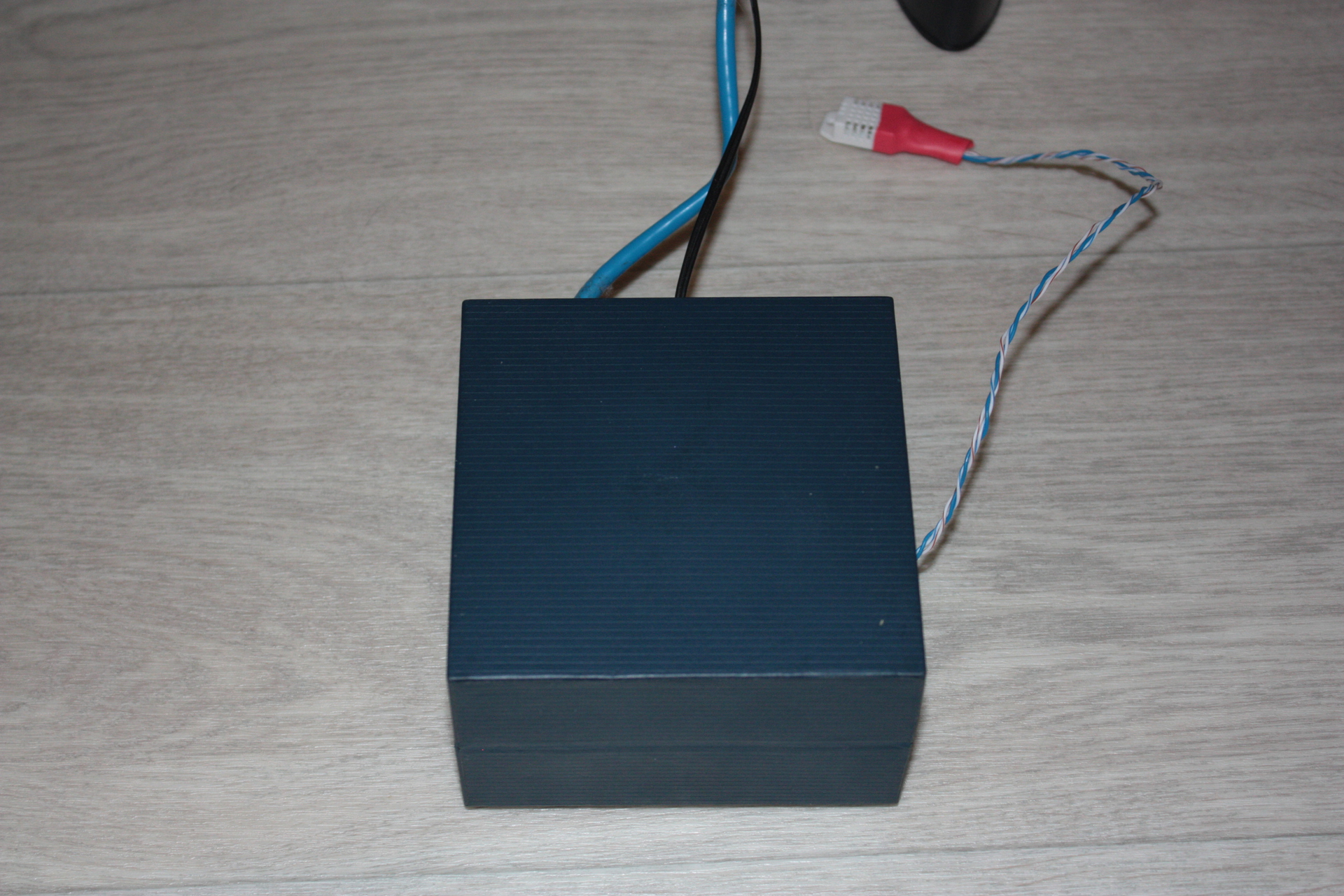
As you can see, the DHT22 dangles from the side, which cannot be placed on the body, much less inside the body, since the device generates a small but sufficient amount of heat to make the temperature sensor lie. As an example, the temperature readings from the BMP085 sensor located inside the case, which are consistently 2 degrees above the correct value.
Server part
The first thought that comes to mind when you are going to make a piece for storing the numbers and then display them: you are certainly not the first to try to invent this wheel. The brief-investigate of the Internet showed that the range of solutions is quite wide, from “what are you, not a programmer chtoli? here's a VisualBasic for you, program ”, until“ here's a little tune up and everything works out of the box ”. The truth, as always, is somewhere in the middle. On the one hand, it is clear that in order to make everything beautiful, you will have to invest in the code thoroughly, this can easily quench any enthusiasm. On the other hand, boxed solutions never do what they want, lacking customization. I slowly led to the fact that there is a wonderful project Majordomo (smartliving.ru), whose goal is to create a platform for a smart home.“What is a smart weather station enough for — not part of a smart home?” I thought and sat down to study the question. The beauty of Majordomo IMHO is that quite simple, typical things work there with a little setup and right out of the box. But there is always the possibility, if you don’t like something, add (the benefit is sufficiently developed scripting tools in PHP) or rewrite (the platform is open, source code is available). Of the tools supported by Majordomo, the objects in which data can be updated from the outside via an HTTP request and home pages, where you can draw everything your heart desires and supports HTML / JS / CSS and the rest of the zoo web technologies, come in handy.But there is always the possibility, if you don’t like something, add (the benefit is sufficiently developed scripting tools in PHP) or rewrite (the platform is open, the source code is available). Of the tools supported by Majordomo, the objects in which data can be updated from the outside via an HTTP request and home pages, where you can draw everything your heart desires and supports HTML / JS / CSS and the rest of the zoo web technologies, come in handy.But there is always the possibility, if you don’t like something, add (the benefit is sufficiently developed scripting tools in PHP) or rewrite (the platform is open, the source code is available). Of the tools supported by Majordomo, the objects in which data can be updated from the outside via an HTTP request and home pages, where you can draw everything your heart desires and supports HTML / JS / CSS and the rest of the zoo web technologies, come in handy.
Under Arduino sensors, a separate class of objects with the following structure was organized:

DeviceID is the device address that participates in the microprotocol packet. The description of the other fields speaks for itself. The logic of work is as follows:
When the central unit transmits data, among the objects of this class is searched for one in which the DeviceID and SensorType match the transferred ones. For the object found, the transferred value is set (the value from the float field of the microprotocol package), UpdatedTime is set to Now, Actual is set to 1, the timer is activated for the ActualityPeriod time in the future, which will reset Actual to 0. The last focus is necessary to understand that The sensor is irrelevant, since it has not been updated for a long time, in case something happened to the central unit or the sensor itself. There are several such sensors:

The values of these sensors are then visualized using home pages. I used different pages to display different data, or the same data, but in a form optimized for display on different devices.
Display devices
An old Dell Streak 5 covered with a fair amount of dust was used as a central display device, which [reference to the beginning of the article, in the paragraph with the choice of device for display] looks much more profitable than a 1.8 or 2.2 inch display screen bolted directly to the Arduino and its maximum capable of displaying text and icons 8x8. Being set up to start the Dolphin browser at the start, which opens a page with the weather, he became the ready face of the weather station (and not only the weather station, again announcing a future article on thermostating). Here it should be noted that in the text of the corresponding home page Majordomo had to resort to a set of tricks that put the browser in full screen mode and hide all unnecessary, like the address bar and the Android status bar.
In addition, the data is viewed on the iPhone and iPad mainly spouse, in order to monitor the climatic situation in the nursery.
The result of this technological hodgepodge in photos
Dell Streak:
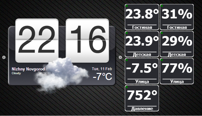
Streak:

12 , :
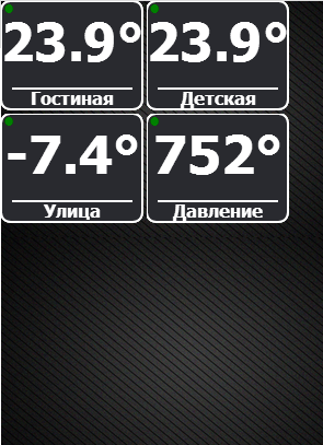
iPhone:
Streak:
12 , :
iPhone:
Testing, conclusions, plans
To date, the system is operated about one and a half months. There are no special complaints about it, except for the central unit that has happened to hang twice with the ENC28J60 completely disconnected (even the link and activity LEDs did not light up). It was treated by removing the power from the unit for a few seconds. I recorded in the reasons for this behavior not very good quality of electricity in the on-board network of the house, which sometimes “rattles”, i.e. disappears for some fraction of a second. How electronics behave in such conditions is not known. As a means of preventing the influence of this factor, the installation of two ionistors on 1F was conceived (one for powering the 5V controller, the second for the Ethernet adapter, 3V3). It was possible to manage a reserve in the form of batteries, but it is much more expensive (the cost of ionistors is tens of rubles,a set of normal batteries will cost half a thousand) is not interesting (I saw batteries many times and see ionistors for the first time) and does not meet the goal (since the goal is to prevent the effect of short-term, a few seconds, nasty effects on the network, and not to power the unit in the absence of electricity ).
It is possible to write to the conclusions that the set of glands copes with its task and has a reserve for expansion in the following directions:
- Expansion of the network of sensors. The central unit is able to receive any data sent via the microprotocol, which means you can conceive not only weather sensors. Example: a water meter and an interface module to an electricity meter that has a clear physical interface — RS232 and an incomprehensible exchange protocol for the time being
- Introduction to the system of executive devices
In the near future plans are:
- The controller of the boiler, which, together with weather sensors, forms a closed system of temperature control in the house. The prototype has already been made and is being tested. I promise to devote a separate article to this work.
- Mentioned electricity and water meters with leak detection module
Source: https://habr.com/ru/post/213405/
All Articles