Radio-controlled switch do it yourself. Part 2 - Testing and Training
This post is a continuation of a series of stories about how you can make a payload switch with your own hands.
In the first part , the hardware component was described: the features of its design and production.
Today's post describes the steps to prepare the Arduino development environment and complete testing of the manufactured module.
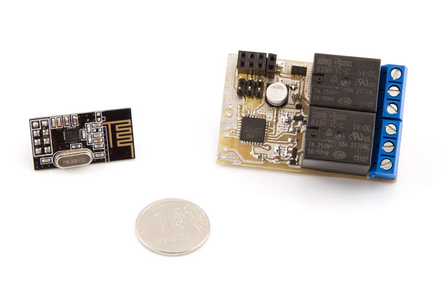
Let me remind you that according to the final of the previous post we received a fully assembled device - all components are in their places.
Now you need to check its performance.
')
The easiest way to do this is as follows: connect a programmer and read the values of fusions.
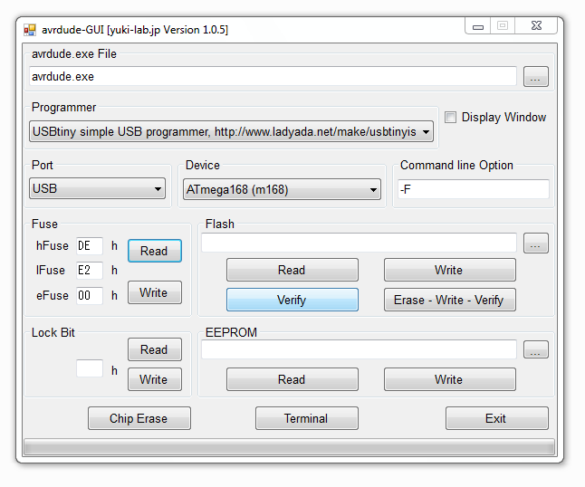
Since the post is focused on beginners, I will use visual tools and show you how to do it as simply as possible: we will use the Avrdude-GUI GUI.
After these simple actions, a window like this will appear:

Now it is necessary to make the minimum settings: select the used programmer (Programmer field), the used port (Port), specify the used MK (Device).
Now we connect the programmer to the computer, and the programmer itself to our board.
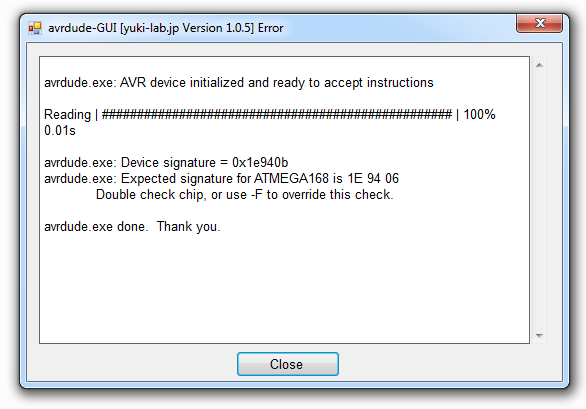
In the section "Fuse" press the button "Read". If everything is done correctly, the fyuz values will appear in the corresponding fields:
Using the same shell, you can write the necessary fyuzy.
In our case, it is required to ensure the operation of the MC from the internal oscillator at a frequency of 8 MHz. To do this, you can use for ATmega168p those values that are shown above in the screenshot.
Now we can proceed to the next stage: checking the possibility of programming the MK and testing the rest of the "periphery" on the board.
To do this, one more preparatory step should be taken: it is necessary to create an appropriate “charge” for the Arduino environment. This is done as follows: you need to open the boards.txt file in the \ ARDUINO \ hardware \ arduino folder with a text editor, where “ARDUINO” is the root folder where the development environment is located.
The following lines must be added to this file:
The first line indicates the “name of the board”, which you will then choose in the programming environment (you can specify whatever you like).
Pay special attention to the parameters that describe the fyuzy, type MK and the frequency at which the device will operate.
After these simple manipulations, you can launch the Arduino environment and make sure that the “new board” appeared in the list of available ones (in the “Service - Board” menu, choose ours: Sensor168p (int8MHz, 1.8V)).
Let me remind you that according to the circuitry, the keys for controlling the relay are connected to the digital pins D3 and D4, and the buttons to the analog A1 and A0.
Let's make the simplest test to check the normal functioning of buttons and relays:
Download this test to our device.
Before downloading, do not forget to select the programmer used in the “Tools” - “Programmer” menu.
Since the programmer is used, the procedure is slightly different - in the “File” menu, select the item “Download using the programmer” (or simply press the key combination Ctrl + Shift + U).
If everything is done correctly, then when the buttons are closed, the corresponding relays will click.
After this, it remains only to check whether everything is in order with the nRF24L01 + connector.
At this stage, we will not write the code, but simply check the electrical circuits: when the programmer is connected (or 5V power supply), we measure the voltage between 1 and 2 pins of the RF24 connector - it should be 3.3V.
Now turn off the programmer (or power supply) and run through all the circuits of the connector for the absence of a short circuit between adjacent ones and the presence of a connection with the corresponding pins MK (see the diagram from the previous post ).
Since our device will later commute a high-voltage load, you should check this part very carefully:
After all the checks you have on hand, the module is fully functional and fully ready for subsequent programming. Your programming environment is also prepared for the next steps.
To be continued ...
Useful links :
In the first part , the hardware component was described: the features of its design and production.
Today's post describes the steps to prepare the Arduino development environment and complete testing of the manufactured module.
To work with the manufactured module you need any ISP programmer. I will use the existing USBtinyISP , you can use the same or any other (for example, make ArduinoISP from the existing Arduino board).
Let me remind you that according to the final of the previous post we received a fully assembled device - all components are in their places.
Now you need to check its performance.
')
Check MK
The easiest way to do this is as follows: connect a programmer and read the values of fusions.
Since the post is focused on beginners, I will use visual tools and show you how to do it as simply as possible: we will use the Avrdude-GUI GUI.
- Download the Avrdude-GUI package here .
- Unpack the archive in any folder.
- Run avrdude-GUI.
After these simple actions, a window like this will appear:
Now it is necessary to make the minimum settings: select the used programmer (Programmer field), the used port (Port), specify the used MK (Device).
Now we connect the programmer to the computer, and the programmer itself to our board.
In the section "Fuse" press the button "Read". If everything is done correctly, the fyuz values will appear in the corresponding fields:
If something went wrong
The following errors are most likely:
1. Somewhere not drunk (or vice versa, "snot"). Then, as a result of an attempt to count fusions, a message appears about this error:
To correct the situation, disconnect the board from the programmer and check the quality of the soldering very meticulously:
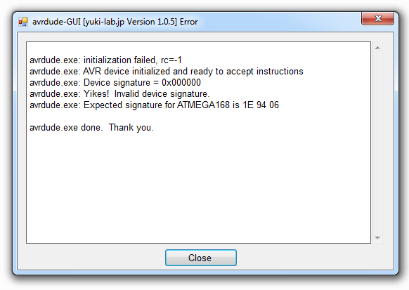
2. Wrong type of MK. The error message will look something like this:
In my case, just such an error arose. This happened due to the fact that I used ATmega168 p , and in the program I chose ATmega168.
These chips are as close as possible, but they have different signatures, which the system carefully reported. At the same time, the program also suggests a solution to the problem - check the correctly selected chip or disable signature verification (by adding the "-F" key in the "Command Line Option" field).
I used exactly the second solution (in this case it is absolutely normal).
It would be more correct, of course, to open the avdude.conf file and add information about the ATmega168p there, but we will leave this on my conscience.
1. Somewhere not drunk (or vice versa, "snot"). Then, as a result of an attempt to count fusions, a message appears about this error:
To correct the situation, disconnect the board from the programmer and check the quality of the soldering very meticulously:
- use a fine needle to check how well all the legs of the MK are soldered
- Look through the magnifying glass for suspicious places
- ring the tester from the ISP connector to the MK,
- Check the power circuit.
2. Wrong type of MK. The error message will look something like this:
In my case, just such an error arose. This happened due to the fact that I used ATmega168 p , and in the program I chose ATmega168.
These chips are as close as possible, but they have different signatures, which the system carefully reported. At the same time, the program also suggests a solution to the problem - check the correctly selected chip or disable signature verification (by adding the "-F" key in the "Command Line Option" field).
I used exactly the second solution (in this case it is absolutely normal).
It would be more correct, of course, to open the avdude.conf file and add information about the ATmega168p there, but we will leave this on my conscience.
Using the same shell, you can write the necessary fyuzy.
In our case, it is required to ensure the operation of the MC from the internal oscillator at a frequency of 8 MHz. To do this, you can use for ATmega168p those values that are shown above in the screenshot.
Fyuza "explain" MK, in which mode it should work. It is possible to prescribe what values (or to understand the values given above) using the AVR fusion calculator, which is available, for example, via this link .
Now we can proceed to the next stage: checking the possibility of programming the MK and testing the rest of the "periphery" on the board.
Preparing the development environment
To do this, one more preparatory step should be taken: it is necessary to create an appropriate “charge” for the Arduino environment. This is done as follows: you need to open the boards.txt file in the \ ARDUINO \ hardware \ arduino folder with a text editor, where “ARDUINO” is the root folder where the development environment is located.
The following lines must be added to this file:
############################################################## s168po8.name=Sensor168p (int8MHz, 1.8V) s168po8.upload.protocol=arduino s168po8.upload.maximum_size=14336 s168po8.upload.speed=19200 s168po8.bootloader.low_fuses=0xe2 s168po8.bootloader.high_fuses=0xde s168po8.bootloader.extended_fuses=0x00 s168po8.bootloader.path=atmega s168po8.bootloader.file=ATmegaBOOT_168_pro_8MHz.hex s168po8.bootloader.unlock_bits=0x3F s168po8.bootloader.lock_bits=0x0F s168po8.build.mcu=atmega168p s168po8.build.f_cpu=8000000L s168po8.build.core=arduino s168po8.build.variant=standard ############################################################## The first line indicates the “name of the board”, which you will then choose in the programming environment (you can specify whatever you like).
Pay special attention to the parameters that describe the fyuzy, type MK and the frequency at which the device will operate.
After these simple manipulations, you can launch the Arduino environment and make sure that the “new board” appeared in the list of available ones (in the “Service - Board” menu, choose ours: Sensor168p (int8MHz, 1.8V)).
Test buttons and relays
Let me remind you that according to the circuitry, the keys for controlling the relay are connected to the digital pins D3 and D4, and the buttons to the analog A1 and A0.
Let's make the simplest test to check the normal functioning of buttons and relays:
// int r1 = 3; // D3 int r2 = 4; // D4 // int b1 = 15; // A1 int b2 = 14; // A0 void setup() { // pinMode(r1, OUTPUT); pinMode(r2, OUTPUT); // pinMode(b1, INPUT); pinMode(b2, INPUT); // digitalWrite(b1, HIGH); digitalWrite(b2, HIGH); } void loop() { // b1 - r1 if (digitalRead(b1) == LOW) { digitalWrite(r1, HIGH); } else { digitalWrite(r1, LOW); } // b2 - r2 if (digitalRead(b2) == LOW) { digitalWrite(r2, HIGH); } else { digitalWrite(r2, LOW); } } Download this test to our device.
Before downloading, do not forget to select the programmer used in the “Tools” - “Programmer” menu.
Since the programmer is used, the procedure is slightly different - in the “File” menu, select the item “Download using the programmer” (or simply press the key combination Ctrl + Shift + U).
If everything is done correctly, then when the buttons are closed, the corresponding relays will click.
The above test sketch does not work “bounce” and is needed solely for a quick check of the functioning of the board.
If something went wrong
There are two typical problems:
In the first case, you need to check all the steps that are described earlier (working with the boards.txt file, correctly selected result board and programmer).
In the second case, the best assistants will again be the circuit diagram, a magnifying glass, a sharp needle and a tester.
- Something is incorrectly done in the Arduino environment (then there are messages about problems with loading in MK).
- Problems in the hardware (in this case, the download is successful, but the relay does not click).
In the first case, you need to check all the steps that are described earlier (working with the boards.txt file, correctly selected result board and programmer).
In the second case, the best assistants will again be the circuit diagram, a magnifying glass, a sharp needle and a tester.
After this, it remains only to check whether everything is in order with the nRF24L01 + connector.
Interface test for nRF24L01 +
At this stage, we will not write the code, but simply check the electrical circuits: when the programmer is connected (or 5V power supply), we measure the voltage between 1 and 2 pins of the RF24 connector - it should be 3.3V.
Now turn off the programmer (or power supply) and run through all the circuits of the connector for the absence of a short circuit between adjacent ones and the presence of a connection with the corresponding pins MK (see the diagram from the previous post ).
High Voltage Check
Since our device will later commute a high-voltage load, you should check this part very carefully:
- Inspect the board very carefully (the part where the relays and terminal blocks are located for connecting the load), eliminate all suspicious places, the soldering should be very reliable. There should be no “extra” connections.
- Call the tester all the circuits, at the same time determine which terminals on the terminals you have are normally closed (NC) and normally open (NO) contacts.
Result
After all the checks you have on hand, the module is fully functional and fully ready for subsequent programming. Your programming environment is also prepared for the next steps.
To be continued ...
Useful links :
Source: https://habr.com/ru/post/212785/
All Articles