Arduino and aquarium
What is common in the north of Italy and tropical fish? But you never know what? - the reader will say. And he will be right. Therefore, I will clarify: it will be about Arduino, more precisely about the automation of aquarium maintenance.
It all started with the fact that the vacation was inexorably approaching. On vacation, I usually want to change the situation. But aquarium fish may not understand this. Not only that - they can not forgive. And I ordered a new filter, an automatic feeder and a timer for household appliances. But the timer was not available. Therefore, I decided to wander around the site of almost the only store (and this is in the city, which is considered a million-plus!) Radio components and devices, and ran into Arduino Uno for 154 UAH. (~ $ 20). More than once read about the device, but in the hands, as they say, did not hold. Bought. And from this moment begins the history of trial, error and victory.
The most important task that I wanted to delegate to Arduino is to control the lighting on a schedule. Yes, from the cannon on the sparrows, but for a guest from Italy (actually from China, but this does not matter) I have some big plans.
Until now, the aquarium was illuminated with an energy-saving light bulb, it was necessary to turn it on and off manually. It is clear that the strict time regime was not maintained, especially on weekends. Now, in order to simplify the task and make lighting more durable, it was decided to switch to 12V LEDs. I bought a meter of waterproof LED strip. Collected the scheme:
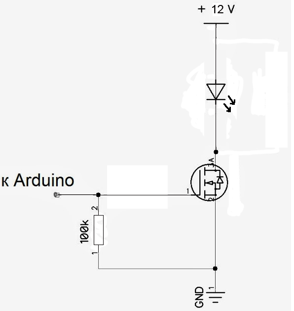
The field-effect transistor dropped out of a non-working computer power supply unit. In general, I tried to use as much as possible what was available at hand. But you can take almost any, for example IRFBC30. The resistor is needed to ensure the reliability of the circuit: the ultralow currents "go to the ground" and the field effect transistor opens and closes only at high and low states at the Arduino pin. It is also recommended that a limiting resistor be set to a hundred or second ohm between the gate and the port pin, but in this scheme it can be neglected.
UPDATE! The comments are still very insistent on the limiting resistor. Well, let's listen. We put a 100 Ohm resistor between the Arduino pin and the gate.
')
Then I found an Internet program in the open spaces (this example was inserted only to explain the structure of the program “on fingers”):
Earned! The LEDs flash occasionally.
Small explanations to the program.
The rest is clear from the comments.
Then there was the question of time synchronization. After all, when you turn off the power and turn it on again, the program will start from scratch. Considered three options: use homemade UPS (which is not so cheap and easy to implement); synchronize with the Internet (the corresponding board is more expensive than my Arduino); synchronize with the clock. Pretty soon I found the RTC (real time clock, yes, it sounds weird in Russian) on the World Wide Web compatible with Arduino.
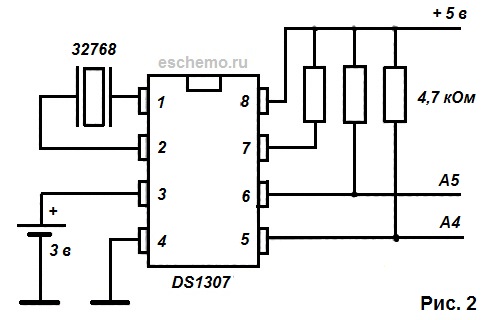
Very simple scheme. Resistors can be set from 4.7 to 10 kΩ. You will also need a DS1307 clock chip and a 32768 Hz clock quartz, battery. The holder for the battery (CR 2032) picked up with the packaging of a computer motherboard. Since historically on the board I already had a transistor for the LED control circuit soldered, I placed the clock nearby.
If suddenly after assembling the watches it is impossible to set the time on the clock or they “stand”, then check the correctness of the connections and their quality. It is necessary to move one wiring from the chip - and the clock behaves badly. And yes, place the DS1307 on a DIP panel.
The clock must be initialized, i.e. set the correct date and time. This can be done as follows.
DS1307 library can be downloaded here .
After the program is loaded into the controller, it is possible to observe in the console (Serial Monitor, Ctrl + Shift + M) how time “runs”.
But back to our schemes and parts.
Then I saw a DS18B20 digital thermometer wiring diagram transmitting data via the 1-Wire interface. There is even a special Arduino library for this thermometer that allows the tightrope walker and fast forward of Bavaria to easily obtain temperature data in a readable form. Connected, played-played - shows -127 ⁰. It turned out that the connection scheme is wrong (and I chose a scheme with active power). The thermometer documentation helped. Moral: the scheme on the site is good, and the official documentation is better.
Below is the correct scheme. You can connect multiple thermometers to a single 1-Wire line. It is advisable to use a coaxial cable.

Then came the turn of the display (well, how to be without displaying the same temperature?). I took the standard text two lines of 16 characters. Hooked up. It worked. He displayed the readings of the thermometer and the clock. I understood that time was not spent in vain. The backlight significantly heated the display, so it turned off.
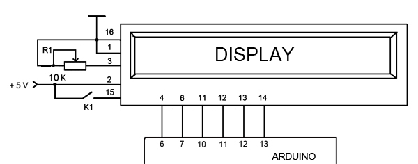
Display wiring diagram.
A trimmer is needed to set the display contrast. Button K1 provides power to the backlight.
The 4th pin of the display is the address signal line. Known as A0 or RS. Depending on whether it is 0 or 1, the display understands whether we have a command on the data line like “move the cursor” or the character code to display.
The 6th pin of the display is the data access permission line. Known as E or Enable. When this line becomes a unit, the display executes the command or outputs a character from the data line.
The 11th, 12th, 13th, and 14th display pins are data lines. Known as DB4, DB5, DB6, DB7.
Clock and display "in the gland."

Now it’s the turn of the power supply, since before that I used two different power supplies: 5V for the display and the clock, and 9V for the Arduino and the LEDs. Again, there was a power supply for 24V, 1.7 A at hand. I’ll say right away that this is not enough for the + Arduino LEDs. It is better to take the PSU at 3A, and control the brightness using PWM. To get the 5 and 10V I needed, I assembled the shemk on the LM317T. Why 10V? According to the Arduino documentation, it’s better not to power more than 12V, LEDs with less voltage should also last longer. Therefore, I decided to get 10V. In fact, it was 10.4V. Again - did not split hairs and collected at a minimum of parts. Scheme.

But if there is time, desire and opportunity, it is still better to assemble a full-fledged impulse power supply unit that would give out at 10-11V to 2-2.5A.
Since the LM317 heat up appreciably, I attached them to the radiator from PII (remember, were there any such slot CPUs from Intel?), Resistors were hinged. Filled the whole thing epoxy. Attention: the LM317 housing is connected to the output leg, so if you mount the LM317 for different voltages on one radiator, then at least N-1 chips must be isolated from the radiator. And all is better. From the side of the radio parts, I covered the radiator with a plastic cover, and left the ribs “bare”. Caught on the eyes of a 9-pin RS232 served as a power connector from the output of the stabilizer.
It's time to put it all together. And then came the difficulty. Although not. Difficulties came when I began to change the temporary connecting wires to permanent. Such, multi-core, I took from the four-wire telephone cables that came to hand.
Spacious housing with a margin in size is, as for me, indecently expensive - $ 10 or more. If I spread the board under the case - there would be no problems, and so I had to improvise. I took the body Maszczyk KM51. The circuit board had to be divided into two parts, Arduino attached to the cover. And all because of the fact that it was too lazy to remake.
It turned out that's what.

Yes, it looks, to put it mildly, not so hot. But you just had to adjust the board to the dimensions and openings of the case, solder pins into it and put Arduino on them. It would be beautiful and reliable. In general - do not do as in the photo above.
In this performance, all this did not work for long - the hack did not survive the weekly vacation. So I had to redo it.
This time I took a suitable board and placed pins on it to connect the Arduino. Or rather two boards, since on the controller board there are two connectors on each side and the distance of 2.54 mm is not maintained for the entire row of pins. It turned out not very aesthetically pleasing, but it works.

Placed items.

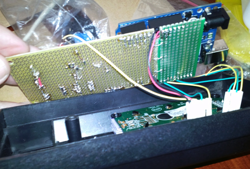
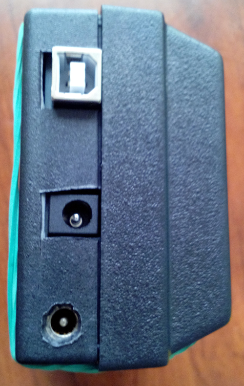
There are three connectors on the board: thermal sensors, LEDs, power supply (just in case you soldered a larger connector, all of a sudden it will be necessary to supply more than one voltage in the future). On the case: USB, Arduino power supply directly (not used), power to the whole circuit (+ 12V).
This time I gave up two voltages, and gave one - because the Arduino issues 5V to one of the connectors. True - the current there is rather weak, but for the operation of the clock and the display is enough. Through a microbutton (visible in the photo above), he supplied power to the backlight. Now you can briefly highlight the screen.
I bought another thermometer and changed the program to reflect the display of two temperatures: in the aquarium and in the room. To connect the DS18B20, it is better to use a cable with a shielding “minus”, but there wasn’t any one at hand - the same telephone four-core wire took all.
Download libraries here: DallasTemperature , OneWire .
The need to turn on / off the aquarium lighting is checked every minute, the temperature - every 30 seconds, and the time is updated every second.
The converted device has worked for a week without any complaints.
Again, in a good way, it was necessary to do a little wrong, and get rid of the wires in general. But I was too lazy to buy a slightly smaller display (I blocked the hole for fastening the case) and spread the board. But if we take, for example, double-sided glass fiber (one-sided, it is hardly possible to manage, given the number of connectors on the controller and the display), to separate the connections, then it is quite possible to get something like this:
When the summer comes, and it happens to be hot here, I also plan to implement the fan control for cooling the aquarium based on the thermometer reading. I consider two options: 12V fans with switching on in the same way as the backlight, or 230V AC fan. In this case, instead of the LEDs, a relay with a control voltage of + 12V and switching 230V is included in the circuit.

In the same way, it is possible to control the heating of the aquarium in winter by switching on a heater in the relay circuit.
What else can be improved from what is already there? For example, turn the backlight on and off gradually using the PWM output. In this case, with a certain interval, you must perform:
where pin is the port number of the Arduino, and value varies from 0 to 255 when turned on and from 255 to 0 if the aquarium light is turned off.
You may also need to turn on the lighting manually. I have a separate lamp for this, but if there is none, it can be implemented with the help of an Arduino. The idea in this case is as follows. One of the inputs of the Arduino through a non-latching button to apply voltage from the output + 5V. Connect the “ground” to the same input through a 10 kΩ resistor. Then monitor the button press:
where buttonPin is the port number to which the button is connected; isLight is a variable that remembers the current state and when you click on the button it changes to the opposite. In this code it is necessary to enable the corresponding on / off lines of the LEDs after the comment. The first time you press the button, the light will turn on, and when it is pressed again, it will turn off.
You can still, and probably need to automate the feeding with the help of Arduino. After all, sold feeders are either expensive or do not have the necessary functionality, or both.
And, of course, about good, it would be necessary to implement the installation of the interval of the lighting without flashing Arduino. For example, assign two or even one buttons to it.
And this is not all that can be implemented on the Arduino. Even with the Arduino Uno, there is the potential for both managing and retrieving data when servicing an aquarium. And this is without significant time and money.
It all started with the fact that the vacation was inexorably approaching. On vacation, I usually want to change the situation. But aquarium fish may not understand this. Not only that - they can not forgive. And I ordered a new filter, an automatic feeder and a timer for household appliances. But the timer was not available. Therefore, I decided to wander around the site of almost the only store (and this is in the city, which is considered a million-plus!) Radio components and devices, and ran into Arduino Uno for 154 UAH. (~ $ 20). More than once read about the device, but in the hands, as they say, did not hold. Bought. And from this moment begins the history of trial, error and victory.
For those who did not face Arduino - I will explain.
This is a hardware and software platform. Iron is based on an Atmel ATmega microcontroller and is equipped with a variety of I / O ports. The software part is the development environment and a set of libraries. Iron, of course, costs some money (in fact, prices, even for originals from Italy, are affordable), and software is free. Downloaded from the official site. With the help of software, you can control I / O ports. Present ports with PWM .
Working with Arduino is pretty easy due to the presence of many libraries. For example, there are libraries for working with temperature sensors, digital and graphic (yes!) Displays, various protocols, etc. In general, you need to connect to one or more ports of Arduino whose electronic circuit you want to manage (or with which you need to receive data), download the appropriate library (if it is not in the standard package), write a program using the Arduino language (based on the Wiring language) Arduino development environment (based on the Processing environment). Fill the compiled program via USB into the Arduino's iron memory, and, voila! - we get the desired result (if everything is done correctly). And, yes, the program remains in the memory of the piece of iron even after turning off the power.
Working with Arduino is pretty easy due to the presence of many libraries. For example, there are libraries for working with temperature sensors, digital and graphic (yes!) Displays, various protocols, etc. In general, you need to connect to one or more ports of Arduino whose electronic circuit you want to manage (or with which you need to receive data), download the appropriate library (if it is not in the standard package), write a program using the Arduino language (based on the Wiring language) Arduino development environment (based on the Processing environment). Fill the compiled program via USB into the Arduino's iron memory, and, voila! - we get the desired result (if everything is done correctly). And, yes, the program remains in the memory of the piece of iron even after turning off the power.
The most important task that I wanted to delegate to Arduino is to control the lighting on a schedule. Yes, from the cannon on the sparrows, but for a guest from Italy (actually from China, but this does not matter) I have some big plans.
Until now, the aquarium was illuminated with an energy-saving light bulb, it was necessary to turn it on and off manually. It is clear that the strict time regime was not maintained, especially on weekends. Now, in order to simplify the task and make lighting more durable, it was decided to switch to 12V LEDs. I bought a meter of waterproof LED strip. Collected the scheme:
The field-effect transistor dropped out of a non-working computer power supply unit. In general, I tried to use as much as possible what was available at hand. But you can take almost any, for example IRFBC30. The resistor is needed to ensure the reliability of the circuit: the ultralow currents "go to the ground" and the field effect transistor opens and closes only at high and low states at the Arduino pin. It is also recommended that a limiting resistor be set to a hundred or second ohm between the gate and the port pin, but in this scheme it can be neglected.
UPDATE! The comments are still very insistent on the limiting resistor. Well, let's listen. We put a 100 Ohm resistor between the Arduino pin and the gate.
')
Then I found an Internet program in the open spaces (this example was inserted only to explain the structure of the program “on fingers”):
Program for beginners
int ledPin = 5; // 5 void setup() { pinMode(ledPin, OUTPUT); // () } void loop() { digitalWrite(ledPin, HIGH); // delay(1000); // 1 digitalWrite(ledPin, LOW); // delay(5000); // 5 } Earned! The LEDs flash occasionally.
Small explanations to the program.
void setup() - this function is launched at each start of the iron. void loop() - fulfills in a cycle.The rest is clear from the comments.
Then there was the question of time synchronization. After all, when you turn off the power and turn it on again, the program will start from scratch. Considered three options: use homemade UPS (which is not so cheap and easy to implement); synchronize with the Internet (the corresponding board is more expensive than my Arduino); synchronize with the clock. Pretty soon I found the RTC (real time clock, yes, it sounds weird in Russian) on the World Wide Web compatible with Arduino.
Very simple scheme. Resistors can be set from 4.7 to 10 kΩ. You will also need a DS1307 clock chip and a 32768 Hz clock quartz, battery. The holder for the battery (CR 2032) picked up with the packaging of a computer motherboard. Since historically on the board I already had a transistor for the LED control circuit soldered, I placed the clock nearby.
If suddenly after assembling the watches it is impossible to set the time on the clock or they “stand”, then check the correctness of the connections and their quality. It is necessary to move one wiring from the chip - and the clock behaves badly. And yes, place the DS1307 on a DIP panel.
The clock must be initialized, i.e. set the correct date and time. This can be done as follows.
Clock initialization program
#include <Wire.h> #include <DS1307.h> void setup() { Serial. begin(9600); RTC.stop(); // RTC.set(DS1307_SEC, 0); // RTC.set(DS1307_MIN, 36); // RTC.set(DS1307_HR, 15); // RTC.set(DS1307_DOW, 2); // RTC.set(DS1307_DATE, 4); / RTC.set(DS1307_MTH, 1); // RTC.set(DS1307_YR, 14); // RTC.start(); // } void loop() { Serial.print(RTC.get(DS1307_HR, true)); // Serial.print(":"); Serial.print(RTC.get(DS1307_MIN, false)); // Serial.print(":"); Serial.print(RTC.get(DS1307_SEC, false)); // Serial.println(" "); delay(1000); } DS1307 library can be downloaded here .
After the program is loaded into the controller, it is possible to observe in the console (Serial Monitor, Ctrl + Shift + M) how time “runs”.
But back to our schemes and parts.
Then I saw a DS18B20 digital thermometer wiring diagram transmitting data via the 1-Wire interface. There is even a special Arduino library for this thermometer that allows the tightrope walker and fast forward of Bavaria to easily obtain temperature data in a readable form. Connected, played-played - shows -127 ⁰. It turned out that the connection scheme is wrong (and I chose a scheme with active power). The thermometer documentation helped. Moral: the scheme on the site is good, and the official documentation is better.
Below is the correct scheme. You can connect multiple thermometers to a single 1-Wire line. It is advisable to use a coaxial cable.
A small lyrical digression.
I did everything wrong in this project: I soldered temporary schemes as ideas arrived, then I adjusted the connections for the case, the corpus, took the parts I had in my hands and practically did not leave room for adding functionality - once everything would have to be done anew ( and still had to!). Therefore, I urge you to do the opposite:
1) determine the functionality;
2) determine the details;
3) select the case on the basis of the first two points;
4) dilute the fee based on the first three points.
And so it is necessary to do in almost any electronic project.
If there is a need to test this or that idea - use special prototyping boards and a set of connections. Yes, I know their prices bite. But believe me, save a lot of time and nerves.
Then came the turn of the display (well, how to be without displaying the same temperature?). I took the standard text two lines of 16 characters. Hooked up. It worked. He displayed the readings of the thermometer and the clock. I understood that time was not spent in vain. The backlight significantly heated the display, so it turned off.
Display wiring diagram.
A trimmer is needed to set the display contrast. Button K1 provides power to the backlight.
The 4th pin of the display is the address signal line. Known as A0 or RS. Depending on whether it is 0 or 1, the display understands whether we have a command on the data line like “move the cursor” or the character code to display.
The 6th pin of the display is the data access permission line. Known as E or Enable. When this line becomes a unit, the display executes the command or outputs a character from the data line.
The 11th, 12th, 13th, and 14th display pins are data lines. Known as DB4, DB5, DB6, DB7.
Clock and display "in the gland."
Now it’s the turn of the power supply, since before that I used two different power supplies: 5V for the display and the clock, and 9V for the Arduino and the LEDs. Again, there was a power supply for 24V, 1.7 A at hand. I’ll say right away that this is not enough for the + Arduino LEDs. It is better to take the PSU at 3A, and control the brightness using PWM. To get the 5 and 10V I needed, I assembled the shemk on the LM317T. Why 10V? According to the Arduino documentation, it’s better not to power more than 12V, LEDs with less voltage should also last longer. Therefore, I decided to get 10V. In fact, it was 10.4V. Again - did not split hairs and collected at a minimum of parts. Scheme.
But if there is time, desire and opportunity, it is still better to assemble a full-fledged impulse power supply unit that would give out at 10-11V to 2-2.5A.
Since the LM317 heat up appreciably, I attached them to the radiator from PII (remember, were there any such slot CPUs from Intel?), Resistors were hinged. Filled the whole thing epoxy. Attention: the LM317 housing is connected to the output leg, so if you mount the LM317 for different voltages on one radiator, then at least N-1 chips must be isolated from the radiator. And all is better. From the side of the radio parts, I covered the radiator with a plastic cover, and left the ribs “bare”. Caught on the eyes of a 9-pin RS232 served as a power connector from the output of the stabilizer.
It's time to put it all together. And then came the difficulty. Although not. Difficulties came when I began to change the temporary connecting wires to permanent. Such, multi-core, I took from the four-wire telephone cables that came to hand.
Spacious housing with a margin in size is, as for me, indecently expensive - $ 10 or more. If I spread the board under the case - there would be no problems, and so I had to improvise. I took the body Maszczyk KM51. The circuit board had to be divided into two parts, Arduino attached to the cover. And all because of the fact that it was too lazy to remake.
It turned out that's what.
Yes, it looks, to put it mildly, not so hot. But you just had to adjust the board to the dimensions and openings of the case, solder pins into it and put Arduino on them. It would be beautiful and reliable. In general - do not do as in the photo above.
In this performance, all this did not work for long - the hack did not survive the weekly vacation. So I had to redo it.
This time I took a suitable board and placed pins on it to connect the Arduino. Or rather two boards, since on the controller board there are two connectors on each side and the distance of 2.54 mm is not maintained for the entire row of pins. It turned out not very aesthetically pleasing, but it works.
Placed items.
In the collection.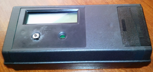

There are three connectors on the board: thermal sensors, LEDs, power supply (just in case you soldered a larger connector, all of a sudden it will be necessary to supply more than one voltage in the future). On the case: USB, Arduino power supply directly (not used), power to the whole circuit (+ 12V).
This time I gave up two voltages, and gave one - because the Arduino issues 5V to one of the connectors. True - the current there is rather weak, but for the operation of the clock and the display is enough. Through a microbutton (visible in the photo above), he supplied power to the backlight. Now you can briefly highlight the screen.
I bought another thermometer and changed the program to reflect the display of two temperatures: in the aquarium and in the room. To connect the DS18B20, it is better to use a cable with a shielding “minus”, but there wasn’t any one at hand - the same telephone four-core wire took all.
The final program.
/* */ #include <Wire.h> // #include <OneWire.h> // 1-Wire #include <DS1307.h> // DS1307 #include <LiquidCrystal.h> // LCD #include <DallasTemperature.h> // 18B20 #define TempPin 2 // pin int ledPin = 3; // , pin 3 LiquidCrystal lcd(6, 7, 10, 11, 12, 13); // OneWire oneWire(TempPin); // , DallasTemperature tempSensor(&oneWire); // long tmIntv = 1000; // long tempIntv = 30000; // , long prvMlsTm = 0; // long prvMlsTemp = 0; // long prvMlsLght = 0; // long lghtIntv = 60000; // / , 1 int lghtStat = 0; // , 1 int upLghtTime = 8; // 8 int downLghtTime = 17; // 17 int isNight = 0; // , .. int prevSec = 0; // // Arduino void setup(){ pinMode(ledPin, OUTPUT); // () tempSensor.begin(); // lcd.begin(16, 2); //, 16 lcd.print("Time:"); // "Time" if (upLghtTime > downLghtTime) { // isNight = 1; } } void printTemp () { // float aTemp; // float rTemp; // tempSensor.requestTemperatures(); // rTemp = tempSensor.getTempCByIndex(0); // 0 aTemp = tempSensor.getTempCByIndex(1); // 1 lcd.setCursor(0, 1); // lcd.print("R: "); lcd.print(rTemp); // lcd.setCursor(7, 1); lcd.print(" A: "); lcd.print(aTemp); // lcd.setCursor(15, 1); lcd.print(" "); lcd.home(); // , 32 } void light () { /// int hr; int isLght = 0; hr = RTC.get(DS1307_HR, true); // if (isNight == 0) { // if (hr >= upLghtTime && hr < downLghtTime) { // isLght = 1; // } else { isLght = 0; } } else { // if(hr - upLghtTime >= 0) { // , isLght = 1; // } else { if(hr < downLghtTime) { // , isLght = 1; // } else { isLght = 0; } } } // : ? if((isLght == 1) && (lghtStat == 0)) { // lghtStat = 1; digitalWrite(ledPin, HIGH); //, } else { if(isLght == 0 && lghtStat == 1) { lghtStat = 0; digitalWrite(ledPin, LOW); //, } } } void printTime () { //- int hr; int minut; int sec; lcd.setCursor(7, 0); hr = RTC.get(DS1307_HR, true); // if( hr < 10) { lcd.print('0'); // 0 10 } lcd.print(hr); lcd.print(":"); minut = RTC.get(DS1307_MIN, false); // if( minut < 10) { lcd.print('0'); // 0 10 } lcd.print(minut); lcd.print(":"); sec = RTC.get(DS1307_SEC, false); // if( sec < 10) { lcd.print('0'); // 0 10 } // , , - if(prevSec == sec) { RTC.start(); } prevSec = sec; lcd.print(sec); } void loop() // { unsigned long currentMillis = millis(); // // , delay(), , // - // // , if(currentMillis - prvMlsTm > tmIntv) { prvMlsTm = currentMillis; printTime(); // - } // , if(currentMillis - prvMlsTemp > tempIntv) { prvMlsTemp = currentMillis; printTemp(); // } // / , if(currentMillis - prvMlsLght > lghtIntv) { prvMlsLght = currentMillis; light(); // - / } } Download libraries here: DallasTemperature , OneWire .
The need to turn on / off the aquarium lighting is checked every minute, the temperature - every 30 seconds, and the time is updated every second.
The converted device has worked for a week without any complaints.
Again, in a good way, it was necessary to do a little wrong, and get rid of the wires in general. But I was too lazy to buy a slightly smaller display (I blocked the hole for fastening the case) and spread the board. But if we take, for example, double-sided glass fiber (one-sided, it is hardly possible to manage, given the number of connectors on the controller and the display), to separate the connections, then it is quite possible to get something like this:
Implementation option
When the summer comes, and it happens to be hot here, I also plan to implement the fan control for cooling the aquarium based on the thermometer reading. I consider two options: 12V fans with switching on in the same way as the backlight, or 230V AC fan. In this case, instead of the LEDs, a relay with a control voltage of + 12V and switching 230V is included in the circuit.
In the same way, it is possible to control the heating of the aquarium in winter by switching on a heater in the relay circuit.
What else can be improved from what is already there? For example, turn the backlight on and off gradually using the PWM output. In this case, with a certain interval, you must perform:
analogWrite(pin, value);where pin is the port number of the Arduino, and value varies from 0 to 255 when turned on and from 255 to 0 if the aquarium light is turned off.
You may also need to turn on the lighting manually. I have a separate lamp for this, but if there is none, it can be implemented with the help of an Arduino. The idea in this case is as follows. One of the inputs of the Arduino through a non-latching button to apply voltage from the output + 5V. Connect the “ground” to the same input through a 10 kΩ resistor. Then monitor the button press:
int isLight = 0; buttonState = digitalRead(buttonPin); if (buttonState == HIGH) { if (isLight == 0) { // isLight == 1; } else { // isLight == 0; } } where buttonPin is the port number to which the button is connected; isLight is a variable that remembers the current state and when you click on the button it changes to the opposite. In this code it is necessary to enable the corresponding on / off lines of the LEDs after the comment. The first time you press the button, the light will turn on, and when it is pressed again, it will turn off.
You can still, and probably need to automate the feeding with the help of Arduino. After all, sold feeders are either expensive or do not have the necessary functionality, or both.
And, of course, about good, it would be necessary to implement the installation of the interval of the lighting without flashing Arduino. For example, assign two or even one buttons to it.
And this is not all that can be implemented on the Arduino. Even with the Arduino Uno, there is the potential for both managing and retrieving data when servicing an aquarium. And this is without significant time and money.
Source: https://habr.com/ru/post/212519/
All Articles