UPS for router
In the beginning was the light, and it was good. Suddenly, the electricity was cut off, and an idea was born.
At home there is a tablet and a pair of phones that allow you to use the Internet without a cord to the outlet. The Internet comes through a 3G modem and is distributed by the router via Wi-Fi. It remains a trifle - to make the router work in the absence of electricity.
')
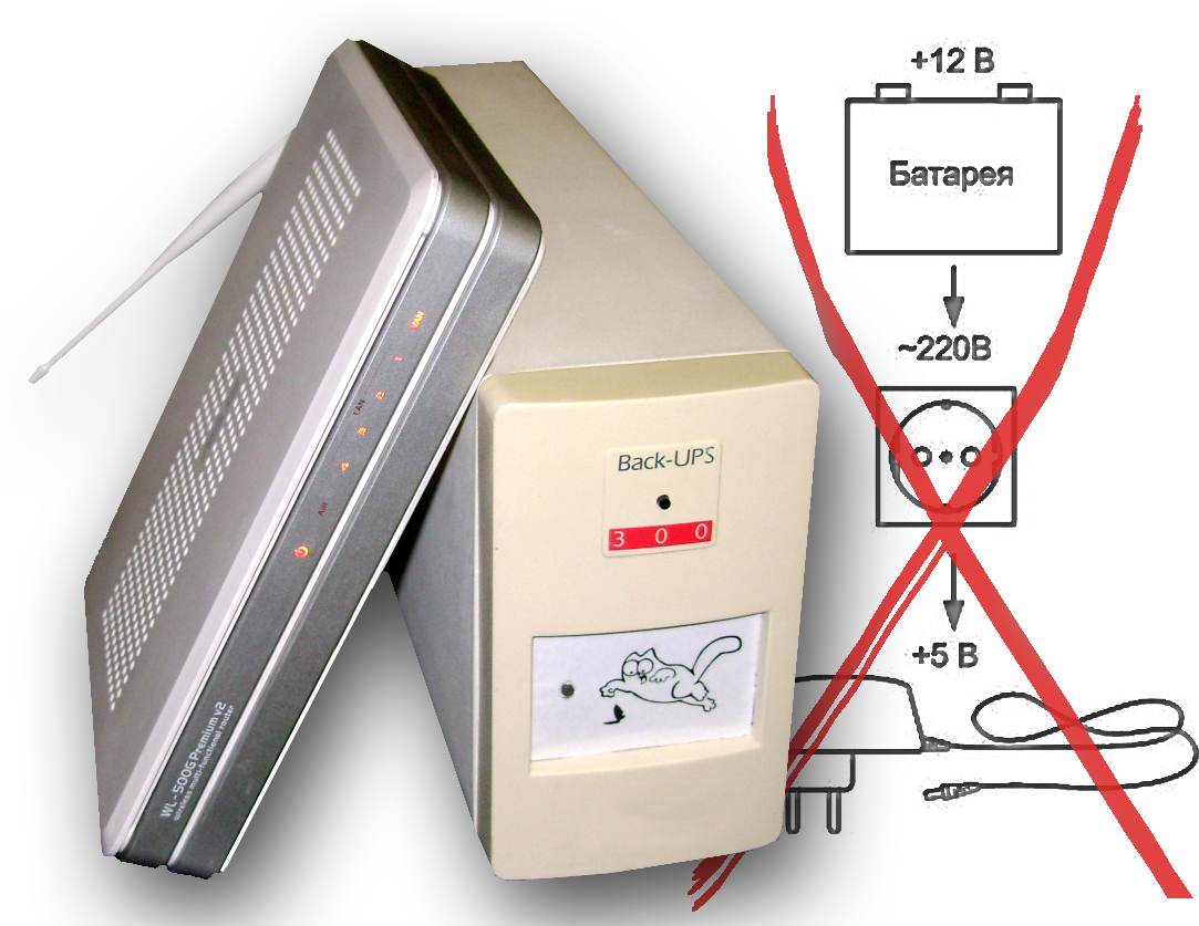
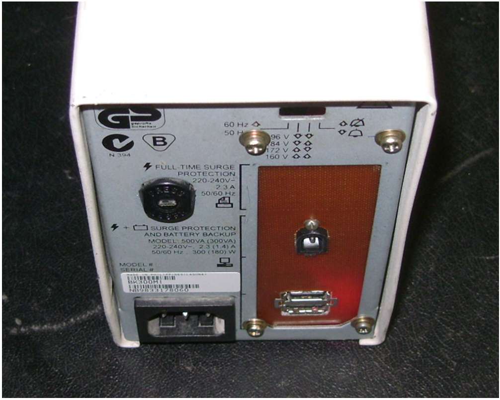
It was here that I remembered an old Uninterruptible Power Supply (UPS) Back-UPS 300. It’s quite a working device, but it has been gathering dust for a long time due to the fact that “it doesn’t draw anything, and what for is needed”.
The idea is to simplify the circuit, eliminating the conversion to 220V, lower 12V immediately to 5V and get decent battery life.
The scheme for back ups 300 was found quite quickly and, after a cursory study, it was decided to take power directly from the battery. That is, for the future of the UPS, only the battery charge circuit is required, and most of the elements of the current circuit are simply not needed. You can disconnect unused circuits by dropping out several resistors and removing the relay.
A voltage converter KIS-3R33S was ordered on ebay. The input voltage is 6V-23V, at the output we get the cherished 5V, 3A.

The router’s native power supply, if you believe the label, delivers up to 2.5 A, so the converter should be enough.
With a long absence of electricity, the UPS will work until it kills the battery, which means you need to install a battery protection device (UZAB). After a brief search, the scheme was chosen: Radiokot
With a slight refinement, it looks like this:

The circuit is almost indistinguishable from the original - added resistors, where necessary, well, and rigidly set the shutdown limit from the 10.5V battery, replacing the trimmer with 2 resistors. Resistors R1 - 4.7kohm and R2 - 4,3kohm were chosen experimentally by the trimmer. Relay using vypayannoe from the main board. Since I do not need the indication, part of the comparator’s conclusions are not involved.
Successful start failed. Current measurements showed the discharge of the battery when running on the network. Chip TL780-15, responsible for charging the battery, regulates the current depending on the voltage at the output, which means that with a charged battery, the current passing through the chip is extremely small, and the battery is used to power the connected device. Yes, and the diodes in the charge circuit are designed for a current of not more than 1A, and this is somewhat not enough for simultaneously charging the battery and powering the router. Even if they are replaced with more powerful elements, surely this small transformer will not stand. It's a pity.
I turn to the plan "B"!
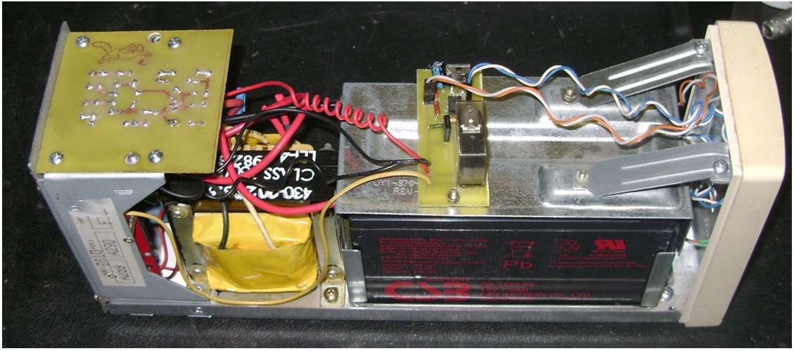
In order for the device to work properly dismantle the main board and return the previously removed transformer back.
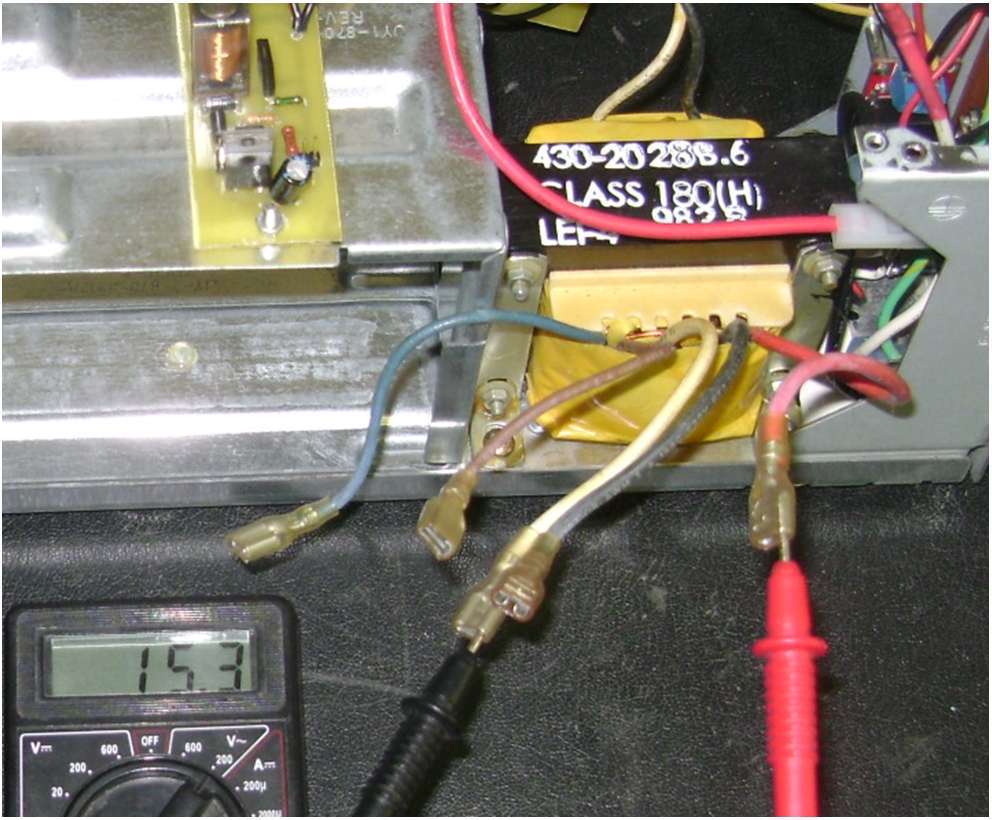
The method of measuring the resistance determine the contacts of the primary winding of the transformer, the winding has the greatest resistance (white and black). Extremely neatly connect it to 220V. Nothing banged, not buzzing, not heated, then Iguess I did everything right. I take measurements of the voltage on the secondary windings, find the appropriate (red and yellow).
The decision is made, you need to separate the charge scheme and the power scheme of the router. For the battery charge will be responsible that same chip from the main board.
I also take (water) from the terminal board, let the UPS be collapsible.
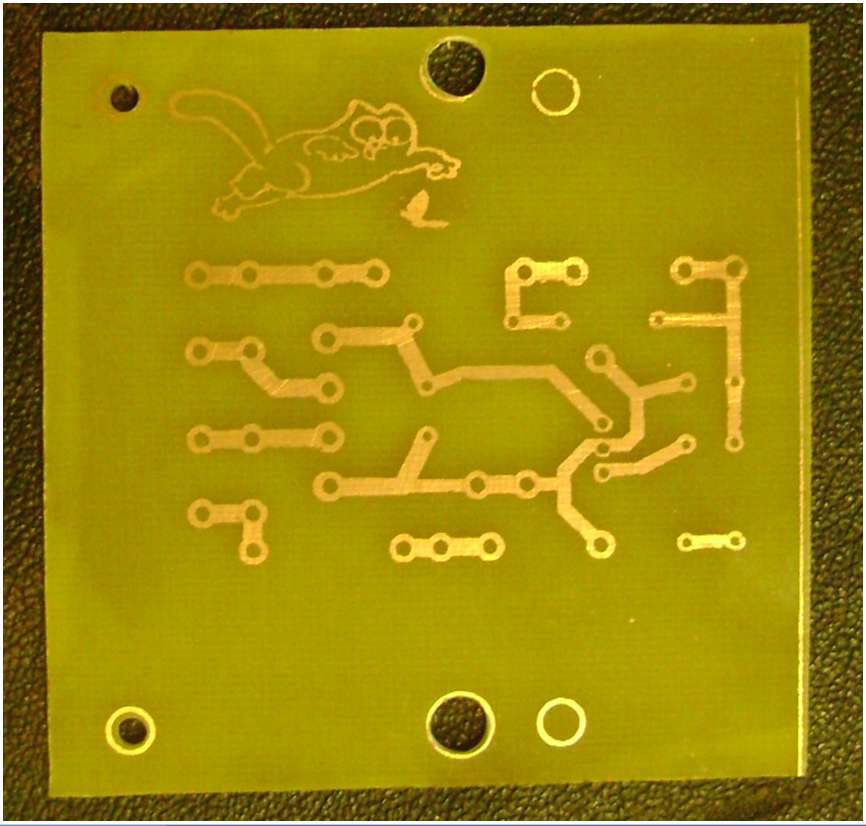
In my head everything came together, it should turn out, I turn to the manufacture of the board. Everything once had to do for the first time. I paint, print, degrease the board, carry it with an iron - the result is unsatisfactory (I began to tear off the sheet without letting it cool down), I clean, print, take it with an iron, let it cool, and soak the stuck sheet. It seems everything turned out. I admire. And then Ostap suffered ... I choose a picture, pick up a size, print it, take it with an iron, soak it.
Everything seems to be okay For the first time, in my opinion, it turned out quite well.
Drill holes, place and solder elements.

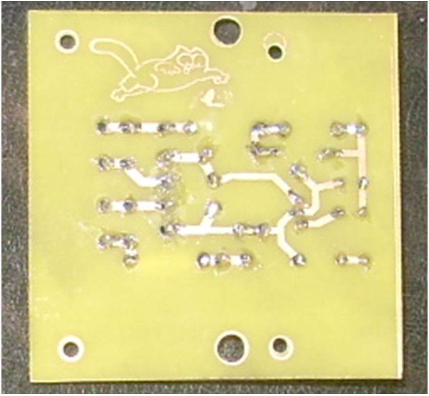
I connect. Everything works - I admire.
Current checking is normal.
Checking the heating elements - heated relay. That's right, and it will warm up! A 12V relay is connected to an 18V circuit. Replaced by 24V. It works even from 10V, it does not heat up, it turns on more quietly. It is good to have a bunch of "trash" at hand.
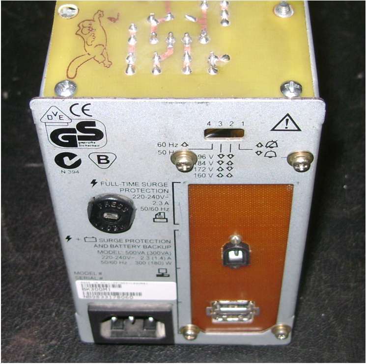
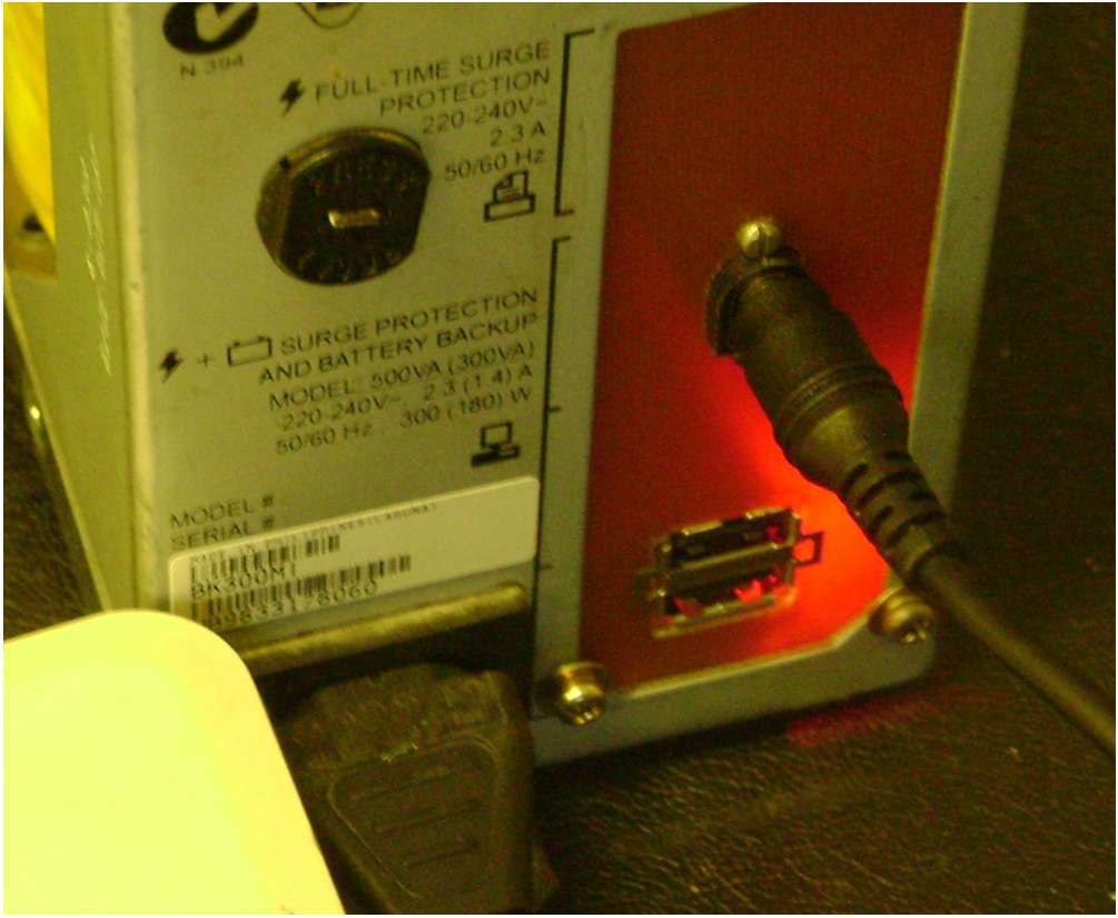
I place the voltage converter and charge USB connectors to the back of the UPS, charge it with a tablet or phone. I also fix the connector for 10V-18V output for powering the router.

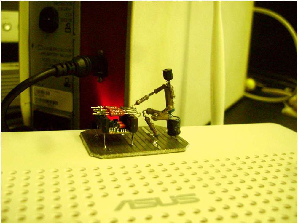
In the router I install the second voltage converter, there is enough space.

Why so ...
A router with a 3G modem is located in the attic, and the UPS must be installed indoors. Accordingly, the cable length is about 7 meters and, to be sure of the stable operation of the router, the supply voltage of 5V is formed in the router itself.
I install additional stiffeners to compensate for the absence of the main board.

I mount the buttons, collect the device, make a print on the face.

No indication was planned, but the voltage converter made its own adjustments.
If I did everything all over again:
1. Drew a scheme before starting work, and not after (as now when writing an article). To keep everything in your head, of course, you can, but there are stupid mistakes.
2. Placed all the items on one board, getting rid of extra wires.
My expenses: DC Converter KIS-3R33S 2pcs. - $ 5.3; opamp LM358N 1pcs - 10rub.
Taking this opportunity, I thank my colleague Dmitry for practical advice and assistance in the manufacture of this device.
PS: The UPS has been working properly since September - the month. Since then, the blackouts have never happened.
At home there is a tablet and a pair of phones that allow you to use the Internet without a cord to the outlet. The Internet comes through a 3G modem and is distributed by the router via Wi-Fi. It remains a trifle - to make the router work in the absence of electricity.
')
It was here that I remembered an old Uninterruptible Power Supply (UPS) Back-UPS 300. It’s quite a working device, but it has been gathering dust for a long time due to the fact that “it doesn’t draw anything, and what for is needed”.
The idea is to simplify the circuit, eliminating the conversion to 220V, lower 12V immediately to 5V and get decent battery life.
The scheme for back ups 300 was found quite quickly and, after a cursory study, it was decided to take power directly from the battery. That is, for the future of the UPS, only the battery charge circuit is required, and most of the elements of the current circuit are simply not needed. You can disconnect unused circuits by dropping out several resistors and removing the relay.
A voltage converter KIS-3R33S was ordered on ebay. The input voltage is 6V-23V, at the output we get the cherished 5V, 3A.
The router’s native power supply, if you believe the label, delivers up to 2.5 A, so the converter should be enough.
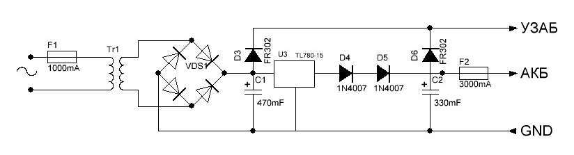
With a long absence of electricity, the UPS will work until it kills the battery, which means you need to install a battery protection device (UZAB). After a brief search, the scheme was chosen: Radiokot
With a slight refinement, it looks like this:
The circuit is almost indistinguishable from the original - added resistors, where necessary, well, and rigidly set the shutdown limit from the 10.5V battery, replacing the trimmer with 2 resistors. Resistors R1 - 4.7kohm and R2 - 4,3kohm were chosen experimentally by the trimmer. Relay using vypayannoe from the main board. Since I do not need the indication, part of the comparator’s conclusions are not involved.
Successful start failed. Current measurements showed the discharge of the battery when running on the network. Chip TL780-15, responsible for charging the battery, regulates the current depending on the voltage at the output, which means that with a charged battery, the current passing through the chip is extremely small, and the battery is used to power the connected device. Yes, and the diodes in the charge circuit are designed for a current of not more than 1A, and this is somewhat not enough for simultaneously charging the battery and powering the router. Even if they are replaced with more powerful elements, surely this small transformer will not stand. It's a pity.
I turn to the plan "B"!
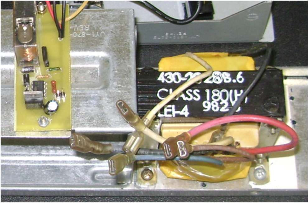
In order for the device to work properly dismantle the main board and return the previously removed transformer back.
The method of measuring the resistance determine the contacts of the primary winding of the transformer, the winding has the greatest resistance (white and black). Extremely neatly connect it to 220V. Nothing banged, not buzzing, not heated, then I
The decision is made, you need to separate the charge scheme and the power scheme of the router. For the battery charge will be responsible that same chip from the main board.
I also take (water) from the terminal board, let the UPS be collapsible.
In my head everything came together, it should turn out, I turn to the manufacture of the board. Everything once had to do for the first time. I paint, print, degrease the board, carry it with an iron - the result is unsatisfactory (I began to tear off the sheet without letting it cool down), I clean, print, take it with an iron, let it cool, and soak the stuck sheet. It seems everything turned out. I admire. And then Ostap suffered ... I choose a picture, pick up a size, print it, take it with an iron, soak it.
Everything seems to be okay For the first time, in my opinion, it turned out quite well.
Drill holes, place and solder elements.
I connect. Everything works - I admire.
Current checking is normal.
Checking the heating elements - heated relay. That's right, and it will warm up! A 12V relay is connected to an 18V circuit. Replaced by 24V. It works even from 10V, it does not heat up, it turns on more quietly. It is good to have a bunch of "trash" at hand.
I place the voltage converter and charge USB connectors to the back of the UPS, charge it with a tablet or phone. I also fix the connector for 10V-18V output for powering the router.
In the router I install the second voltage converter, there is enough space.
Why so ...
A router with a 3G modem is located in the attic, and the UPS must be installed indoors. Accordingly, the cable length is about 7 meters and, to be sure of the stable operation of the router, the supply voltage of 5V is formed in the router itself.
I install additional stiffeners to compensate for the absence of the main board.
I mount the buttons, collect the device, make a print on the face.
No indication was planned, but the voltage converter made its own adjustments.
If I did everything all over again:
1. Drew a scheme before starting work, and not after (as now when writing an article). To keep everything in your head, of course, you can, but there are stupid mistakes.
2. Placed all the items on one board, getting rid of extra wires.
My expenses: DC Converter KIS-3R33S 2pcs. - $ 5.3; opamp LM358N 1pcs - 10rub.
Taking this opportunity, I thank my colleague Dmitry for practical advice and assistance in the manufacture of this device.
PS: The UPS has been working properly since September - the month. Since then, the blackouts have never happened.
Source: https://habr.com/ru/post/212461/
All Articles